Wisi OH 85 H User manual

WISI COMPACT HEADEND
OH 85 H (HDTV)
Betriebsanleitung
Operating instructions
• Empfang von zwei DVB-S/S2-Signalen
und Transmodulation in zwei QAM-
TV-Kanäle
• 2 eingebaute CI-Schnittstellen
• Eingangsfrequenzbereich 950–2150 MHz
• Ausgangsfrequenzbereich 45–870 MHz
• Reception of two DVB-S/S2 signals and
transmodulation into two QAM-TV-channels
• 2 built-in CI interfaces
• Input frequency range 950–2150 MHz
• Output frequency range 45–870 MHz
415 275 a
Schutzkappe für CI-Schächte
Dust cap for CI slot

- 2 -
Headend OH 41 (OK 41 A) (Zubehör) / Headend OH 41 (OK 41 A) (Accessory)
Left Right
Down
Up
W I S I H E A D E N D
O H 5 0 V 1 . 0 0
Stand by
Betriebsspannung am Grundgerät angeschlossen und „Initialisierung der Module“ abgeschlossen.
Handset an Buchse des Grundgerätes einstecken. Durch Drücken einer Taste gelangt man in
das Modul- oder System-Menü.
Stand by
Supply voltage connected to basic unit and wait till mode “Initialising the modules” has finished. Plug
the handset into the socket on the basic unit. Press any key to call the module menu or
System menu.
Modul-Menü / Module meue
Modul 1 OH 85 H/Module 1 OH 85 H
Parameter-Menü / Parameter menu
Modul 2 OH 85/Module 2 OH 85 Cahnnel
DiSEqC
Parameter-Untermenü/Parameter sub-menu
LNB off
Modul 14 OH 88 H/Module 14 OH 88 H
Modul-Menü / Modul menu
▲▼ Tasten / keys — Modul 1… 14 wählen/Select module 1...14
▶Taste/keys — Weiter zum Parameter-Menü/Move to parameter sub-menu
◀Taste/keys — Zurück / Back
Hinweis: Nach erfolgter Programmierung ziehen Sie
das Handset ab.
Note: After programming disconnect the handset.

- 3 -
Headend OH 41 (OK 41 A) (Zubehör) / Headend OH 41 (OK 41 A) (Accessory)
Parameter-Menü / Parameter menu
▲▼ Tasten / keys — Parameter wählen / Select parameter
▶Taste/keys — Weiter zum Parameter-Untermenü / Move to parameter sub-menu
◀Taste/keys — Zurück/Back
Parameter-Untermenü / Parameter sub-menu
◀▶ Tasten / keys — Zu ändernde Stelle wählen
Cursor steht unter der Stelle z.B. 1894
Bei Überschreiten des dargestellten Zahlenbereiches, zurück zum
Parameter-Menü
Select the digit to be changed
Cursor is below the digit, e.g. 1894
If the permissible range is exceeded, the unit returns to the parameter menu
▲▼ Tasten / keys — Wert ändern z.B. 1894 in 1834
Change the value, e.g. change 1894 to 1834
Speichern / Saving data
Autom. nach Verlassen des Parametermenüs oder ca. 60 Sekunden nach der letzten Eingabe.
Data are saved automatically after leaving the parameter menu, or 60 seconds after the last entry.
Front-LED / Front LED indication
rot/red kein Eingangssignal / no input signal
grün/green Eingangssignal wird dekodiert / decoding input signal
blinkt rot (langsam) Modul wird gestartet
flashing red (slow) Module is booting
blinkt rot (schnell) LNB-Speisung am Modul kurzgeschlossen
flashing red (fast) Short circuit of the LNB feeding at the module
blinkt gelb (schnell) Eingangssignal wird analysiert, Parameter am Modul oder Eingangsteil
werden eingestellt (kann bis zu 2 Min. dauern)
flashing yellow (fast) Analyzing the input signal, Parameters at the module or the input section will
be configured (can take up to 2 min.)
blinkt gelb (langsam) zeigt Datenüberlauf im Ausgangskanal
flashing yellow (slow) shows data overflow at the output channel

- 4 -
Vorgehensweise OH 85-Modul-Inbetriebnahme:
Parametermenüs siehe nächste Seiten
Bitte Reihenfolge einhalten:
1. SAT-Signal an Eingangsbuchse anlegen, geg. CAM Modul mit Karte einstecken
2. Grundgerät mit Modul einschalten
3. Startet Gerät nicht, Eingangsbuchse auf Kurzschluß prüfen, geg. DC-Trennglied am Eingang
einfügen
4. Eingangsparameter: DiSEqC, Sat-IF und SymRate, für Kanal A und B einstellen
5. Modulmenü verlassen und warten bis Eingangs LED stabil länger 10 s grün wird
6. Eingangssignalparameter überprüfen Sat-Lev > 50 dBµV
Sat-CNR > 12 dB
Sat-BER <1.00e-7
sind die Eingangssignalparameter zu schlecht, Einstellungen und Antennenausrichtung geg.
korrigieren.
7. Wird ein CAM-Modul verwendet, unter CAMName prüfen ob dieses vom OH-Modul
erkannt wurde. Ist dies nicht der Fall (oder Anzeige von CAMinit), Modulmenü verlassen
und 5 Min warten, dann erneut versuchen. Sollte weiterhin noCAM angezeigt werden,
bitte die Hardware des CAM-Moduls überprüfen.
8. Ausgangsfrequenz F-Out einstellen und geg. Ausgangsmodulationsparameter Q-Rate,
Q-Mode, SpecInv, ChOffs verändern.
9. Filtermodus unter PID-Mode auswählen
select: Ausgangs-TS = Programme welche unter Program ausgewählt werden
transp.: Ausgangs-TS = alle Programme des Eingangs-TS
10. Im Menü Program, im select Filtermodus Progamme auswählen(*).
Sollen Programme im select oder transp. Modus über ein CAM-Modul entschlüsselt werden,
bitte nochmals mit ($) auswählen. Einstellung beim Verlassen kann bis zu 1 Min. in
Anspruch nehmen.
11. Modulmenü zur Modulauswahl verlassen um eingestellte Parameter im Modul
abzuspeichern.
12. Bei Filtermodus select, im Menü stuff überprüfen ob Anteil der Stuffing-Packete im
Ausgangssignal noch min. 20% beträgt. Bei unterschreiten der 20%, unter Program ein
Programm abwählen.

- 5 -
OH 85 module commissioning procedure:
Parameter menu see on the following pages
Please follow the configuration as described below:
1. Wire the signals at the input, if need be plug in a CAM with smart card
Connect SAT signals to F connector.
2. Switch on the basic unit with the module
3. If the device doesn‘t start, please check the F connector for a short-circuit, if needed insert
a DC block at the input
4. Input parameter: set DiSEqC, Sat-IF and SymRate for channel A and B
5. Leave the module menu and wait until the input LED lights up green for more than 10 s
6. Check the input signal parameters Sat-Lev > 50 dBµV
Sat-CNR > 12 dB
Sat-BER <1.00e-7
if the input signal parameters are too bad, adjust the settings and the antenna
orientation if needed.
7. If a CAM is used, check in the menue CAMName if the module is detected.
If not (or CAMinit is displayed), leave the module menue, wait 5 min and try again.
If furthermore noCAM is displayed please check the hardware of the CAM.
8. Set output frequency F-Out and adjust the output modulation parameters
Q-Rate, Q-Mode, SpecInv, ChOffs if need be.
9. Select „filter mode“ in the menue PID-Mode
select: output TS = programms which are selected under the Progam menu
transp.: output TS = all programms of the input TS
10. In the select filter mode, choose the programs in the menu Program(*).
If programms shall be decrypted with a CAM in the select or transp mode, please select
them again with ($). Save and adjust the settings by leaving the menu can take up to 1 min.
11. Leave the module menue to select another module and save the adjusted parameters.
12. At filter mode select, check in the menu stuff the rate of the stuffing packets in the output
signal (min. 20%). If the value is under 20%, deselect a program in the menu Program.

- 6 -
Bedienung / Instructions
* Werden die Eingangsparameter SAT-IF oder SymRate verändert, so werden
Programmauswahl und Entschlüsselung gelöscht.
* If the input parameters SAT-IF or SymRate are changed, the program and
decryption selection will be cleared.
Kanalauswahl
A/B A = Oberer Eingang B = Unterer Eingang
Channel Selection
A/ B A = Upper input B = Lower input
Channel
Sat-IF*Eingangsfrequenzwahl
950–2150 MHz Eingangsfrequenz des gewählten Kanal-Tuners
Input frequency selection
950–2150 MHz input frequency of the tuner of the selected
channel
SymRate*Eingangssymbolrate
1000–45000 kSym/s Symbolrate des gewählten Kanal-Tuners
Input symbol rate
1000–45000 kSym/s symbol rate of the tuner of the selected channel
DVBMode Typ des empfangenen SAT-Signals
DVB-S1 .......................DVB-S1 Signal wird vom Tuner dekodiert
DVB-S2 .......................DVB-S2 Signal wird vom Tuner dekodiert
Signal? ........................Es kann kein Eingangssignal dekodiert werden
Type of the satellite signal at the input
DVB-S1 .......................DVB-S1 signal will be decoded by the tuner
DVB-S2 .......................DVB-S2 signal will be decoded by the tuner
Signal? ........................No input signal can be detected
DiSEqC Eingangsebenenwahl
LNB off .......................keine LNB-Speisung
DC 14V .......................Ebenenwahl mit analogen Schaltkriterien
DC 18V
14V 22kHz
18V 22kHz
SAT1VL1...SAT16HH4 ....Ebenenwahl mit digitalen Schaltkriterien
Level Selection
LNB off .......................no LNB supply
DC 14V .......................level selection with analog protocol
DC 18V
14V 22kHz
18V 22kHz
SAT1VL1...SAT16HH4 ....level selection with digital protocol

- 7 -
Bedienung / Instructions
CAMName Name des CAM-Modules
no CAM Kein CAM-Modul vorhanden
CAM init CAM-Modul wird initialisiert, Menü verlassen und
1 Minute warten
Name of the CAM-module
no CAM no CAM-module available
CAM init CAM-Modul will be initialized, leave the menu and
wait 1 minute
Sat-CNR Signal/Rauschabstand Eingangssignal
in dB Bis ca. 10 dB Dekodierung des Eingangssignals
mit Bitfehlerrate 0
Signal to noise ratio of the input signal
in dB The Bit error rate is 0 for a SNR > 10 dB
Sat-BER Bitfehlerrate Eingangssignal
<1.00e-7 Bitfehlerrate des dekodierten Signales
Bit error rate of the input signal
<1.00e-7 Bit error rate of the input signal
Sat-Lev Eingangspegel des empfangenen SAT-Signals
in dBμV Pegel des dekodierten Eingangsignals
Dekodierung ist ab 45 dBµV möglich.
Input level of the satellite signal at the input
in dBμV Level of the decoded input signal
Decoding works from 45 dBµV
Menü des CAM-Modules
Kann nicht bei jedem CAM dargestellt werden.
CAM menue
Can not be displayed for any type of module
CAM info
PID-Mode DVB-Filtermodus
select ..........................Die unter Program markierten Programme
werden in den Ausgangs-TS eingefügt.
transp .........................Der Eingangs-TS wird komplett zum Ausgang
durchgelassen.
DVB filter mode
select ..........................Programs marked in the column “programs” will be
inserted into the output transport stream.
transp ..........................The input-TS passes the unit directly through.

- 8 -
Bedienung / Instructions
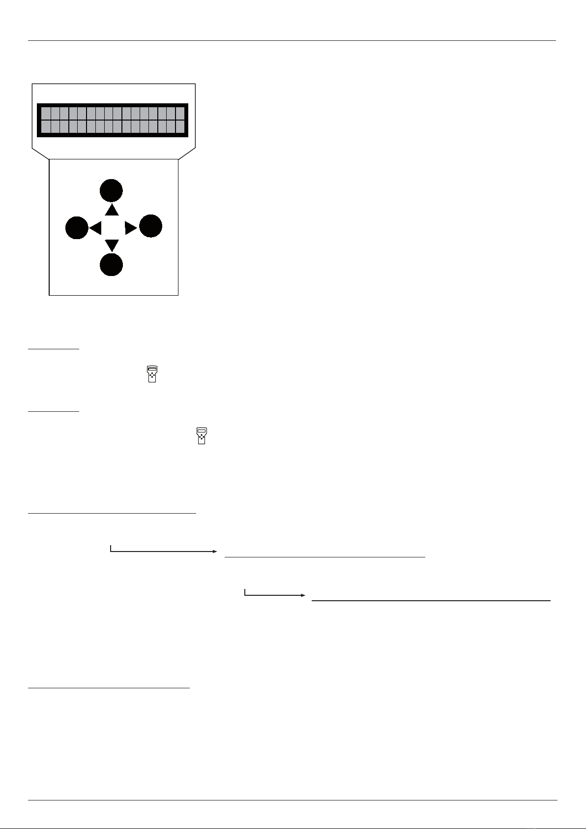
Program Programmauswahl
1 Das Erste _T .........Pgm.-Name; „_“ = FTA; T = TV
2 zdf_neo _T* ........Pgm.-Name; „_“ = FTA; T = TV; „*“ = ausgewählt
3 Sky Cinema#T$ ........Pgm.-Name; „#“ = scrambled; „$“ = descramble
4 NDR Kultur _R .........Pgm.-Name; „_“ = FTA; R = Radio
Programme selection
1 Das Erste _T .........Pgm.-Name; “_” = FTA; T = TV
2 zdf_neo _T* .......Pgm.-Name; “_” = FTA; T = TV; “*” = selected
3 Sky Cinema#T$ ........Pgm.-Name; “#” = scrambled; “$” = descramble
4 NDR Kultur _R .........Pgm.-Name; “_” = FTA; R = Radio
Die Darstellung dient nur als Beispiel und ist aus verschiedenen Transpondern zusammengefügt. Hier
werden die vorhandenen Services dargestellt. Der Service wird mit einer laufenden Nummer darge-
stellt, dann folgt der Service-Name. Die Zeichen „_“ oder „#“ zeigen den Verschlüsselungsstatus des
Eingangssignales an: „_“ steht für FTA (free to air) nicht verschlüsselt und „#“ steht für einen ver-
schlüsselten Service. Das nächste Zeichen gibt den Servcie-Typ an „T“ = TV, „R“ = Radio,
„H“ = TV-HD. Ein Service kann durch Drücken der Links-Taste ausgewählt werden, es wird ein „*“
ganz rechts im Display dargestellt. Wird die linke Taste nochmals betätigt, so wird der Service zur
Entschlüsselung hinzugefügt, der „*“ wird dann durch ein „$“ ersetzt. Wird die Links-Taste nochmals
betätigt, so wird der Service wieder abgewählt.
Achtung:
Befindet sich der PID-Filter im Transparent-Modus, so können keine Services aus der Liste entfernt
werden und es kann bei den einzelnen Services nur zwischen „*“ ausgewählt und „$“ entschlüsselt
gewählt werden.
The following description is only an example, which is combined from services of different transpon-
ders. It displays the available services.
The services are represented with a consecutive number, followed by the service name. The symbol
“_” or “#” are showing the status of the decryption: “_” stands for FTA (free to air), and “#” stands for
an encrypted service. The next symbol shows the type of service: “T” for TV, “R” for radio and “H“ for
HD-TV. One service can be selected by pushing the left-key, and a “*” symbol appears at the right
hand side on the display. By pushing the same key again, the selected service wil be added to the list
for decryption, and the symbol “*” will be replaced by the symbol “$”. By pushing the left button
another time, the selected service will be removed from decryption.
Attention:
If the PID-filter operates in transparent mode, any service can‘t be removed from the list, it only can
be selected between “*” and “$”.

- 9 -
Bedienung / Instructions
Ausgangsfrequenz
474,00 45,00–870,00 in 0,25-MHz-Schritten
Output frequency
474,00 45,00–870,00 in 0,25-MHz-steps
F-Out
Q-Rate* QAM-Ausgangssymbolrate
6900 kS/s 1000–7499 kSym/s ist Q-Stuf auf off
geschaltet, so wird die aktuelle Datenrate am QAM-
Modulator angezeigt.
QAM symbol rate the output
6900 kS/s if Q-stuff is set to “off”, it displays the current
symbol rate
Q-Mode QAM Ausgangsmodulationsart
16 QAM Hier wird die Modulationsart des QAM-
32 QAM Modulators eingestellt.
64 QAM
128 QAM
256 QAM
QAM-modulation scheme at the output
16 QAM Selection of the modulation scheme for the
32 QAM QAM output.
64 QAM
128 QAM
256 QAM
Out-Att Ausgangsdämpfungssteller
7 dB 0–15 dB in 1-dB-Schritten
Output attenuator
7 dB 0–15 dB in 1-dB-steps
*Achtung: Symbolrate ist von Kanalbandbreite abhängig
ChOffs = 7 MHz > Q-Rate = 6111 kS/s
ChOffs = 8 MHz > Q-Rate = 6900 kS/s
*At t ent io n: Symbol rate is dependent on the channel bandwith
ChOffs = 7 MHz > Q-Rate = 6111 kS/s
ChOffs = 8 MHz > Q-Rate = 6900 kS/s

- 10 -
Bedienung / Instructions
SpecInv Invertierung des QAM-Ausgangssignals
normal Hier kann das QAM-Ausgangssignal invertiert
invert werden.
Inverting of the QAM output signal
normal The QAM output signal can be inverted.
invert
Stuff. Stuffing des QAM-Ausgangssignals
Total Data Stuf Hier wird die Gesamtrate Total,
50871 35810 31% die genutzte Datenrate Data und der sich
daraus ergebenden Protzentsatz der
Stuffing-Daten ausgegeben.
Bit-stuffing for the QAM output signal
Total Data Stuf Total outputs the total data rate,
50871 35810 31% data stands for the used data rate.
Stuf is the calced stufing rate in per cent.
* Achtung: Mit Bandbreite muss Symbolrate geändert werden,
siehe oben.
*At t ent io n: The symbol rate must be changed with the bandwidth,
see symbol rate.
OUT BW* Kanalbandbreite der QAM-Ausgangskanäle
8/7 MHz Bandbreite wird an allen Kanälen gleichzeitig
zwischen 7 und 8 MHz umgestellt.
Channel bandwith of the QAM output
channels
8/7 MHz Bandwidth will be changed in all channels
between 7 and 8 MHz simultaneously.
EMMFilt PID-Filter-Menü
on Wird dieses Filter auf „on“ gesetzt, so
off werden bei entschlüsselten Programmen ($)
die EMM‘s und ECM‘s ausgefiltert und die CAT korrigiert.
PID filter menue
on if this filter set to „on“ the EMMs and ECMs will be filtered
off out and the CAT will be corrected for decrypted
programms ($)

- 11 -
Bedienung / Instructions
NITGen NIT Konfiguration
NIT off es wird keine eigene NIT generiert,
eine vorhandene NIT wird durchgereicht
extern* extern eingespielte (z.B. über USB oder Web-Interface) NIT
wird eingefügt.
NIT configuration
NIT off no own NIT will be generated,
an existing NIT will be passed through
extern* external generated (ex. over USB or Web-interface) NIT will be
inserted.
PAT Mon PAT-Monitoring
on Das PAT-Monitoring überwacht Änderungen der Versions-
off information der PAT und PMTs. Bei einer Änderung werden die
PID-Filter im Ausgangsmodulator aktualisiert (select mode).
Zusätzlich werden die Änderungen in die Entschlüsselung
übernommen. Dies wird insbesondere bei der dynamischen
Änderung des Transportstromes benötigt z.B. bei
Regionalumschaltung.
PAT-Monitoring
on The PAT monitoring monitors the changes of the version
off information in the PAT and PMTs. In case of a change the PID
filter at the output modulator will be updated (select mode).
In addition, the changes will be adopted for the decryption.
This is in particular needed in the dynamic change of the
transport stream for example at regional switching.
ModOut Modulation des Ausgangssignals
auto Hier kann der gewählte Ausgangskanal durch
on Wahl von „off“ komplett abgeschaltet werden.
off Wird „auto“ gewählt, so wird die Modulation nur
bei vorhandenem TS eingeschaltet.
Modulation of the output signal
auto The selected output channel can be switched off
on completely by choosing the option “off”. If “auto”
off has been selected, the modulator is only active,
when a TS-signal appears at the input.

- 12 -
OH 85 Modul Bootloader-Version
V1.72 Hier wird die Bootloader-Version des Modules aus-
gegeben.
OH 85 module bootloader version
V1.72 It displays the bootloader version of the module.
BL-Ver
OH 85 Modul-ID
12345678 Zeigt die 8-stellige Modul-ID an, diese wird zur
Lizenzgenerierung benötigt.
OH 85 module ID
12345678 It displays the identifier of the module, whitch is
necessary for the license generation.
Mod-ID
ModVer Ausgangsmodulator-Version
00000023 Hier wird die Software-Version des QAM-
Modulators ausgegeben.
Output modulator version
00000023 It displays the software version of the QAM
modulator.
Bedienung / Instructions
HW-Ver OH 85 Modul Hardware-Version
V4.00 Hier wird der Hardware-Stand des OH 85
Modules ausgegeben. Wird vom Software-
Update benötigt.
OH 85 module hardware version
V4.00 It displays the hardware version whitch is needed
for software updates.
SW-Ver OH 85 Modul Software-Version
V1.00 Hier wird die Software-Version des OH 85
Modules dargestellt. Diese ändert sich geg.
nach einem Software-Update.
OH 85 module software version
V1.00 It displays the software version of the module. It
may change in case of a software update.

- 13 -
Bedienung / Instructions
OH 85 Modul Update
no Durch Wahl von „yes“ kann hier gezielt ein
yes Software-Update an dem gewählten OH Modul
durchgeführt werden.
Insert USB Stick USB Stick mit OH 85 Software in OH 50 USB-
Anschluss einstecken.
Abbruch durch gleichzeitiges drücken der
4 Bedientasten am Handset (Gerät startet neu).
V1_59.bin_ Als erstes wird immer die Software mit der
höchsten Versionsnummer angezeigt. Durch die
„Up“ „Down“ Tasten kann, wenn vorhanden,
aber auch eine andere Version ausgewählt werden.
Die Versionen sind aufsteigend sortiert. Durch Drü-
cken der Rechts-Taste wird die Version für das
Update ausgewählt.
Start Update:Yes Nun bei Start Update „Yes“ wählen und mit der
V1_59.bin „Rechts-Taste“ bestätigen. Das Update wird dann
gestartet. Mit „No“ wird das Update der Modul-
software übersprungen.**
OH 85 module update
no A controlled software update of the selected
yes module can be done by selecting “yes”.
Insert USB Stick Connect a USB-stick with the OH 85 software to the
USB-connector.
To abort, press all four keys of the handset
simultaneously. (The module will reboot).
V1_59.bin_ It displays the software with the highest version
number first. Other versions can be selected with
the “Up” and “Down” keys. The versions are
sorted in ascending order. The selection of the
version can be done by the “right”-key.
Start Update:Yes Now select Start Update “yes”, and confirm it
V1_59.bin with the “right”-key. The update will be started.
Selecting “no” skips the update of the module soft-
ware.
Update*
*Update: Bevorzugt Auto-Update-Funktion verwenden (siehe OH 50-Anleitung).
**Achtung: Wurde das Update abgebrochen oder ist fehlgeschlagen, über
OH 50 ein Auto-Update durchführen. Dazu im Standby USB-Stick einstecken
und Auto update auswählen.
*Update: Use preferred the Auto update function (see OH 50 manual).
**At te nti on: If the update was cancelled or failed perform a auto update over
the OH 50 basic unit. In standby mode insert a USB stick and select the auto
update menu.

- 14 -
OH 85 Werkseinstellungen
no Durch Wahl von „yes“ werden Moduleinstellung mit
yes Werkseinstellungen (siehe Anhang) überschrieben.
OH 85 Factory settings
no If „yes“ is selected the module setting are
yes overwritten with the factory settings (see appendix)
Factory
Bedienung / Instructions

- 15 -
Eingang / Input
Eingangsimpedanz / Input Impedance 75 Ω
Eingangsfrequenzbereich / Input frequency range 950–2150 MHz
Eingangsfrequenzschritte / Input frequency steps 1 MHz
Rückflußdämpfung am Eingang / Input return loss >8 dB
ZF-Frequenz/-Bandbreite / IF-frequency / -bandwidth none (Zero-IF)
Eingangspegelbereich / Input level range 47–80 dBµV
AFC / AFC ±10 MHz
Modulationsart / Modulation scheme QPSK, 8PSK
Symbolrate / Symbol rate 1–45 MS/s
Filterung / Filtering Nyquist √ cos
Dämpfung / Roll-Off 20% / 25% / 30%
FEC outer code / FEC outer code BCH
FEC inner code / FEC inner code LDPC (1/2, 3/5, 2/3, 3/4, 4/5 5/6, 8/9, 9/10)
Datenformat / Data format EN302307
Spektrale Invertierung / Spectral inversion C-Band/KU-Band
Ausgang / Output
Ausgangsimpedanz / Output impedance 75 Ω
Ausgangsfrequenz (Kanal A) / Output frequency (channel A) 45–870 MHz
Frequenzschritte / Frequency steps (channel A) 250 kHz
Frequenzstabilität / Stability of output frequency ±30 kHz
Ausgangskanal Bandbreite / Output channel bandwidth (bonded) 2 x 8 MHz
(Abhängig von QAM-Symbolrate / depending on QAM symbolrate)
Ausgangspegel / Output level 88–103 dBµV
Amplitudengang / Stability of output level ±1 dB
Störabstand / Spurious
innerhalb Kanal / inside TV-channels ≥50 dB
außerhalb Kanal / outside a TV-channel ≥50 dB
S/N / SNR ≥45 dB
MER / MER ≥ 40 dB
Modulation / Modulation 16-, 32-, 64-, 128-, 256-QAM
Symbolrate / Symbolrate 3,45–7,5 Ms/s
Filterung / Filtering Nyquist √ cos
Dämpfung / Roll-off 15 %
FEC outer code / FEC outer code RS (204, 188, 16)
Spektrale Invertierung / Spectral inversion normal/inverted
Verschachtelung / Interleaving Conv., I=12
Bit stuffing / Bit stuffing yes
PCR-Korrektur / PCR correction yes
PID Filterung / PID-filtering yes
Technische Daten / Specifications

- 16 -
Allgemeine Daten / General specifications
Abmessungen / Dimensions 220 (253*) x 105 x 29,5 mm
Anschlüsse / Connectors *with F-connector
RF-input 2 x F-connector
RF-output 1 x F-connector
Power Connector on board
Control Connector on board
Stromaufnahme (ohne CAM-Modul oder LNB-Versorgung) /
Current consumption (without CAM module or LNB-supply) 0,75 A /12,5 V
Leistungsaufnahme / Power consumption <11 W
LNB-Speisung (mit 22 kHz/DiSEqC-Modulator) /
LNB power (with 22 kHz/DiSEqC modulator) 12 V / 0,3 A max
Betriebstemperaturbereich / Operating temperature range -20 °C to + 55 °C
Solltemperaturbereich / Nominal temperature range +5 °C to + 55 °C
Technische Daten / Specifications

- 17 -
VHF - Band I
Kanal Mittenfrequenz Bandbreite
Channel Center frequency Bandwith
2 50,5 7
3 57,5 7
4 64,5 7
VHF -untere Sonderkanäle
Kanal Mittenfrequenz Bandbreite
Channel Center frequency Bandwith
S 2 114,5 7
S 3 121,5 7
S 4 128,5 7
S 5 135,5 7
S 6 142,5 7
S 7 149,5 7
S 8 156,5 7
S 9 163,5 7
S 10 170,5 7
VHF -Band III
Kanal Mittenfrequenz Bandbreite
Channel Center frequency Bandwith
5 177,5 7
6 184,5 7
7 191,5 7
8 198,5 7
9 205,5 7
10 212,5 7
11 219,5 7
12 226,5 7
VHF – obere Sonderkanäle
Kanal Mittenfrequenz Bandbreite
Channel Center frequency Bandwith
S 11 233,5 7
S 12 240,5 7
S 13 247,5 7
S 14 254,5 7
S 15 261,5 7
S 16 268,5 7
S 17 275,5 7
S 18 282,5 7
S 19 289,5 7
S 20 296,5 7
Ausgangskanaltabelle / Output channel list
VHF - Hyperband – Sonderkanäle
Kanal Mittenfrequenz Bandbreite
Channel Center frequency Bandwith
S 21 306 8
S 22 314 8
S 23 322 8
S 24 330 8
S 25 338 8
S 26 346 8
S 27 354 8
S 28 362 8
S 29 370 8
S 30 378 8
S 31 386 8
S 32 394 8
S 33 402 8
S 34 410 8
S 35 418 8
S 36 426 8
S 37 434 8
S 38 442 8
UHF - Band IV
Kanal Mittenfrequenz Bandbreite
Channel Center frequency Bandwith
21 474 8
22 482 8
23 490 8
24 498 8
25 506 8
26 514 8
27 522 8
28 530 8
29 538 8
30 546 8
31 554 8
32 562 8
33 570 8
34 578 8
35 586 8
36 594 8
37 602 8

- 18 -
Kanal A / Channel A
Menüpunkt Einstellung
Menue Setting
DiSEqC LNB off
Sat-IF 1237 MHz
SymRate 27500 kSym/s
PIDMode transp.
NITconf off
F-Out 474 MHz
Out-Att 7 dB
Q-Rate 6900 kSym/s
Q-Mode 256 QAM
OutBW 8 MHz
EMMFilt on
PATMon on
NITGen NIT off
ModOut on
Kanal B / Channel B
Menüpunkt Einstellung
Menue Setting
DiSEqC LNB off
Sat-IF 1354 MHz
SymRate 27500 kSym/s
PIDMode transp.
NITconf off
F-Out 482 MHz
Out-Att 7 dB
Q-Rate 6900 kSym/s
Q-Mode 256 QAM
OutBW 8 MHz
EMMFilt on
PATMon on
NITGen NIT off
ModOut on
Ausgangskanaltabelle / Output channel list
Werkseinstellungen / Factory settings
UHF - Band V
Kanal Mittenfrequenz Bandbreite
Channel Center frequency Bandwith
38 610 8
39 618 8
40 626 8
41 634 8
42 642 8
43 650 8
44 658 8
45 666 8
46 674 8
47 682 8
48 690 8
49 698 8
50 706 8
51 714 8
52 722 8
53 730 8
54 738 8
55 746 8
56 754 8
57 762 8
58 770 8
59 778 8
60 786 8
61 794 8
62 802 8
63 810 8
64 818 8
65 826 8
66 834 8
67 842 8
68 850 8
69 858 8

- 19 -
DiSEqC Zuordnungstabelle / DiSEqC allocation table
DiSEqC-Ebene Standardzuordnung
SAT1 LNB A (z.B.: Astra) vertikal Low-Band
SAT2 LNB A (z.B.:Astra) horizontal Low-Band
SAT3 LNB A (z.B.: Astra) vertikal High-Band
SAT4 LNB A (z.B.: Astra) horizontal High-Band
SAT5 LNB B (z.B.: Eutelsat) vertikal Low-Band
SAT6 LNB B (z.B.: Eutelsat) horizontal Low-Band
SAT7 LNB B (z.B.: Eutelsat) vertikal High-Band
SAT8 LNB B (z.B.:Eutelsat) horizontal High-Band
SAT9 LNB C vertikal Low-Band
SAT10 LNB C horizontal Low-Band
SAT11 LNB C vertikal High-Band
SAT12 LNB C horizontal High-Band
SAT13 LNB D vertikal Low-Band
SAT14 LNB D horizontal Low-Band
SAT15 LNB D vertikal High-Band
SAT16 LNB D horizontal High-Band
DiSEqC level Standard allocation
SAT1 LNB A (ex.: Astra) vertical Low-Band
SAT2 LNB A (ex.:Astra) horizontal Low-Band
SAT3 LNB A (ex.: Astra) vertical High-Band
SAT4 LNB A (ex.: Astra) horizontal High-Band
SAT5 LNB B (ex.: Eutelsat) vertical Low-Band
SAT6 LNB B (ex.: Eutelsat) horizontal Low-Band
SAT7 LNB B (ex.: Eutelsat) vertical High-Band
SAT8 LNB B (ex.:Eutelsat) horizontal High-Band
SAT9 LNB C vertical Low-Band
SAT10 LNB C horizontal Low-Band
SAT11 LNB C vertical High-Band
SAT12 LNB C horizontal High-Band
SAT13 LNB D vertical Low-Band
SAT14 LNB D horizontal Low-Band
SAT15 LNB D vertical High-Band
SAT16 LNB D horizontal High-Band
Bei Rückfragen bitte Software-Version,
Hardware-Version und Einstellungen angeben.
Please specify the software version, hardware version
and your settings if you have any questions.

- 20 -
WISI Communications GmbH & Co. KG
Empfangs- und Verteiltechnik
Wilhelm-Sihn-Straße 5–7
75223 Niefern-Oeschelbronn, Germany
Tel.: +49 900 - 1117722, Fax: +49 7233 - 66-320,
Technical Modifications reserved. WISI cannot be held
liable for any printing error.
10/16
Table of contents
Other Wisi Computer Hardware manuals