9
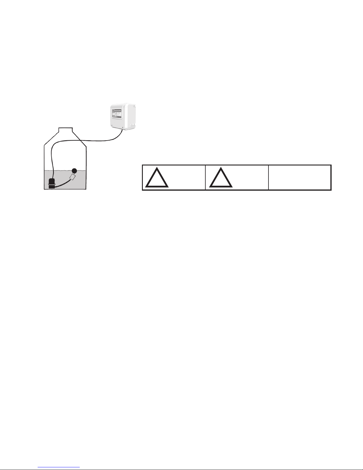
Important: The pumps must not be put into
operation, or even tested, unless the system is
filled with water.
Make sure that the storage tank is filled with a
sufficient quantity of water. The submersible
pump should be completely immersed in wa-
ter and the float switch must be floating.
Basic operating principle
with two pressure pumps
Top-up with mains water
Commissioning
1. Venting and filling of the pump integrated in the wall unit by the loading pump:
Undo the venting/filling screw plug on the pump integrated in the wall unit;
connect only the loading pump to the electrical supply and wait until water
starts to escape from the screw plug; close the screw plug; pull out the elec-
trical plug for the loading pump and connect to the wall unit (blue socket on
underside of the wall unit).
2. Open the valves at the appliances.
3. Connect the OPTIMA to the electricity supply.
4. As soon as system has been bled, close the valves at the appliances! The
OPTIMA unit is ready to operate as soon as the maximum system pressure
is reached.
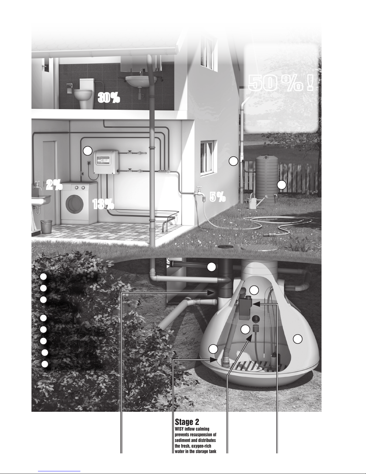
Design and operating principle
The innovative technology of the OPTIMA is based on a hydro-mechanical con-
trol concept which combines „traditional“ control by automatic switches with
the utilization of mechanical flow effects, but without the use of any additional
electronic control components.
The OPTIMA system developed by WISY essentially operates with two pressure
pumps: The submersible pump (or „loading pump“) of the OPTIMA system is
installed in the storage tank. It is equipped with a fine suction filter and a float
switch.
The loading pump pumps the rainwater to the normal-suction, multi-stage cen-
trifugal pump in the wall unit. As a result of the admission pressure, the cen-
trifugal pump is required only to pump and the mains water top-up inlet pipe
remains closed.
If a valve at one appliance (e.g. toilet flushing system) is opened, the pressure in
the circuit drops. When the factory-set pump starting pressure (1.5 bar) on the
automatic switch is reached, both pumps of the rainwater unit start up. When
the valves at all appliances are closed again, the pump control system (automa-
tic switch) turns off both pumps when the operating pressure is reached.
Note: If a „drip irrigation“ system (often computer-controlled) is to be connected
as an appliance to the OPTIMA, a small expansion vessel (around 15 l capacity)
must be installed downstream of the wall unit in the rainwater circuit. The expan-
sion vessel used for this purpose must be of the „flow-through“ type.
Switchover to mains water top-up is fully automatic. If the storage tank is empty,
the flow switch turns off the loading pump. Since the admission pressure then
drops to zero, mains water is automatically sucked out of the top-up tank of the
OPTIMA system. The water level in the top-up tank then falls, causing the float
valve for the mains water inlet to open so that mains water can be supplied to
the centrifugal pump.
If it is necessary to temporarily operate the OPTIMA system exclusively in mains
water operation (e.g. to carry out maintenance on the storage tank), then the
loading pump need only be electrically disconnected from the wall unit (remove
plug from socket on OPTIMA unit!).
The mains water top-up system is implemented as an open outlet in accordance
with DIN EN 1717 (formerly DIN 1988/4). Furthermore, a continuous exchange of
water takes place automatically in the mains top-up tank.
The tank can be topped up with approximately 95 litres of mains water per minu-
te if required. The mains water top-up tank has a storage capacity of 9 litres and
is also fitted with an emergency overflow (DN 70) as an additional precaution.
Every time the OPTIMA system starts up, a measurement of the tank fill level
is triggered. The clock dial indicates the level in %. When the measurement is
complete, the needle gradually drops back to the 0 position again.
A pressure gauge in the sight glass of the OPTIMA indicates the relevant system
pressure at which the rainwater unit is currently operating.
When the system is completely empty of water, the dry run protection system
integrated in the automatic switch shuts down both pumps.
Shutdown of loading pump
Water exchange in the mains water
top-up tank
Operating pressure indicator
Integrated dry run protection