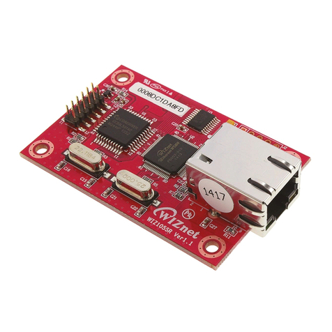
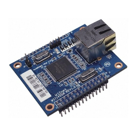
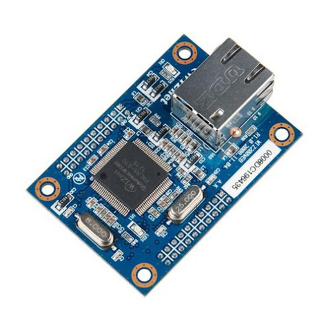
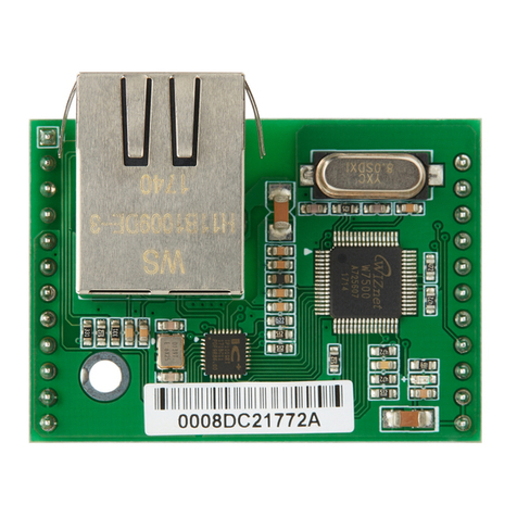
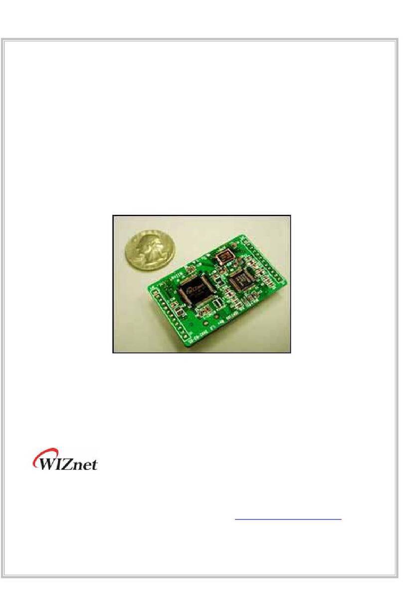
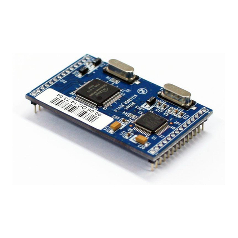
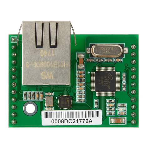
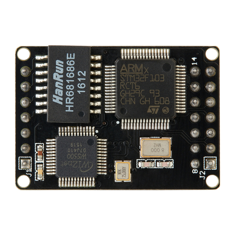
Wiznet IGM7100 User manual

IGM7100 User’s manual
Version 1.1

G GGGGGGGGGGGGGGGGGGGGGGGGGGGGG G
G
oGpGjG~¡GO~pSGpUPG YG
COPYRIGHT NOTICE
Copyright 2002 WIZnet Inc. All Rights Reserved
Technical Support
E-mail: support@wiznet.co.kr
Tel: 82-2-547-9709
Fax: 82-2-547-9711
For more information, visit our website at http://www.wiznet.co.kr

G GGGGGGGGGGGGGGGGGGGGGGGGGGGGG G
G
oGpGjG~¡GO~pSGpUPG ZG
Table of Contents
1.GRead First................................................................................8G
1.1.GProduct Contents.........................................................8G
1.2.GProduct Specification...................................................8G
1.2.1.GIGM7100 Module ..................................................8G
1.2.2.GIGM7100 Test board..............................................8G
2GOverview..................................................................................9G
3GHardware Specification........................................................... 11G
3.1.GIGM7100 Module (Model number: IGM7100) .............. 11G
3.2.GIGM7100 Test board(model number: DKIGM7100)......12G
3.3.GPin Assignment and Dimension..................................13G
3.4GMemory map .............................................................16G
3.4.1GSST version........................................................16G
3.4.2GAtmel version......................................................17G
3.5GMiscellaneous (IGM7100 Test Board).........................18G
3.5.1.GEthernet Interface...............................................18G
3.5.2.GSerial Interface...................................................19G
3.5.3.GLED....................................................................20G
4.GInstallation .............................................................................21G
4.1.GHardware Connection................................................21G
4.1.1.GNetwork connection ............................................21G
4.1.2.GSerial Connection ...............................................21G
4.1.3.GPower Connection...............................................22G
4.1.4.GEntire System Connection...................................23G
4.2.GSoftware Installation..................................................24G

G GGGGGGGGGGGGGGGGGGGGGGGGGGGGG G
G
oGpGjG~¡GO~pSGpUPG [G
4.2.1.GInstallation Process.............................................24G
4.2.2.G“IGM_Cfgtool.exe” Features................................28G
4.2.3GIGM_Pcutil.exe Features.....................................31G
5GTest Operation........................................................................33G
5.1GStep 1 .......................................................................34G
5.1.1GNetwork configuration .........................................34G
5.1.2GIGM7100 Environment Setup...............................36G
5.1.3GConfirming Operation..........................................43G
5.2GStep 2 .......................................................................46G
5.2.1GNetwork Configuration.........................................46G
5.2.2GIGM7100 Environment Setup...............................47G
5.2.3GConfirming Operation..........................................48G
5.3GStep 3 .......................................................................52G
5.3.1GNetwork Configuration.........................................52G
5.3.2GConfirming Operation..........................................53G
6GAuxiliary Functions(Firmware Uploading) ................................54G
6.1GWhen using “IGM_Cfgtool.exe” program.....................54G
6.2GWhen doing serial upload ..........................................60G

G GGGGGGGGGGGGGGGGGGGGGGGGGGGGG G
G
oGpGjG~¡GO~pSGpUPG \G
Illustrations
[Image 2-1] IGM7100 Test board connected to serial device and PC..... 9
[Image 3-1] IGM7100 Module Frontal View..........................................11
[Image 3-2] IGM7100 Module Rear View.............................................11
[Image 3-3] IGM7100 Test Board ........................................................12
[Image 3-4] IGM7100 Module Pin Assignment.....................................13
[Image 3-5] IGM7100 Module Dimension.............................................15
[Image 3-6] Serial Pin Assignment of IGM7100 Test Board..................19
[Image 4-1] IGM7100 Test Board Network Connection.........................21
[Image 4-2] IGM7100 Test Board and Serial Device Connection ..........21
[Image 4-3] IGM7100 Test Board Power Connection............................22
[Image 4-4] Network Configuration......................................................23
[Image 4-5] Initialization window to install IGM7100 utility...................24
[Image 4-6] Installation folder selection window(1)..............................25
[Image 4-7] Installation Folder selection window(2).............................26
[Image 4-8] Installation start window...................................................26
[Image 4-9] Installing window .............................................................27
[Image 4-10] Installation finish window................................................27
[Image 4-11] “IGM_Cfgtool.exe” Initialization Window..........................28
[Image 4-12] “IGM_PCutil.exe” Initialization Window ...........................31
[Image 5-1] RS-232 based serial communication system.....................33
[Image 5-2] Design Step.....................................................................33
[Image 5-3] Step 1 Network Configuration...........................................34
[Image 5-4] “IGM_Cfgtool.exe” Initialization Window ...........................36
[Image 5-5] Board Results List after Running “Find Board”..................37

G GGGGGGGGGGGGGGGGGGGGGGGGGGGGG G
G
oGpGjG~¡GO~pSGpUPG ]G
[Image 5-6] Initial Setup Value of Located Boards...............................38
[Image 5-7] Board A Sample Setup .....................................................40
[Image 5-8] Board B Sample Setup.....................................................41
[Image 5-9] Ping test..........................................................................42
[Image 5-10]”IGM_PCutil.exe” Program Window .................................43
[Image 5-11] “IGM_PCutil.exe” Connection Window ............................44
[Image 5-12] Step 1 Network Configuration.........................................46
[Image 5-13] Step 2 Network Configuration.........................................47
[Image 5-14]”IGM_Pcutil.exe” Program Window ..................................48
[Image 5-15]”Network Part” Setup Window..........................................49
[Image 5-16]”IGM_PCutil.exe” Connection Window .............................50
[Image 5-17] Step 2 Network Configuration.........................................52
[Image 5-18] Step 3 Network Configuration.........................................53
[Image 6-1] “IGM_Cfgtool.exe” Initialization Window ...........................54
[Image 6-2] Board Search Window......................................................55
[Image 6-3] Upload Selection Window.................................................56
[Image 6-4] Firmware Selection for Upload .........................................57
[Image 6-5] Firmware Uploading.........................................................58
[Image 6-6] Uploading Complete.........................................................59
[Image 6-7] Hyper Terminal Window....................................................61

G GGGGGGGGGGGGGGGGGGGGGGGGGGGGG G
G
oGpGjG~¡GO~pSGpUPG ^G
Tables
[Table 2-1] IGM7100 Module Specification .......................................10
[Table 3-1] IGM7100 Module Pin Functions......................................14
[Table 3-2] Serial Pin Description.....................................................20

G GGGGGGGGGGGGGGGGGGGGGGGGGGGGG G
G
oGpGjG~¡GO~pSGpUPG _G
1. Read First
1.1. Product Contents
IGM7100 module
IGM7100 test board
Product manual
IGM7100 test board schematic
Adaptor:5V,500mA
Serial cable
LAN cable (cross over cable)
CD
1.2. Product Specification
1.2.1. IGM7100 Module
Processor: 8bit MCU and 32K Flash (64K expandable)
Memory: 32K Flash (inside MCU), 32K SRAM
Interface: 2x12 2mm TTL
Protocol: TCP, UDP, IP, ARP, ICMP, Ethernet MAC
Power: 3.3V, 150mA
1.2.2. IGM7100 Test board
Interface:DB9(RS-232), RJ-45 (transformer embedded)

G GGGGGGGGGGGGGGGGGGGGGGGGGGGGG G
G
oGpGjG~¡GO~pSGpUPG `G
j
jj
jG
GG
G
Y
YY
YG
GG
G v
vv
vG
GG
G
IGM7100 is a gateway module that converts RS-232 protocol into
TCP/IP protocol. It enables remote gauging, managing and control
of a device through the network based on Ethernet and TCP/IP by
connecting to the existing equipment with RS-232 serial interface.
In other words, IGM7100 is a protocol converter that transmits the
data sent by serial equipment as TCP/IP data type and converts
back the TCP/IP data received through the network into serial data
to transmit back to the equipment.
[Image 2-1] IGM7100 Test board connected to serial device and
PC
z
zz
z
l
ll
lG
GG
G
l
ll
lG
GG
G
z
zz
z
l
ll
lGo
GoGo
GoG
G
Gk
GkGk
GkG
GG
G
pnt^XWW
pnt^XWWpnt^XWW
pnt^XWWG
G

G GGGGGGGGGGGGGGGGGGGGGGGGGGGGG G
G
oGpGjG~¡GO~pSGpUPG WG
[Table 2-1] IGM7100 Module SpecificationG
Category Specification
Protocol TCP, UDP, IP, ARP, ICMP, Ethernet MAC
Network interface 10/100 Base-T Ethernet (Auto detection)
Serial port 1 RS-232 port (TTL type)
CPU SST 89C54
(8bit MCU and 16K Flash)
Atmel T89C51RC2-RLTIL
(8bit MCU and 32K Flash)
•CPU will be changed into Atmel
Serial line format 8data, 1stop, none parity
Serial flow control XON/XOFF, CTS/RTS
Serial signal TXD, RXD, RTS, CTS, DTR, DSR, GND
Software Remote download and configuration possible
Transmission speed 1200bps ~ 230Kbps
Memory 32K Flash (inside MCU), 32K SRAM
Temperature -10’C ~ 80’C (Operating), -40~85’C (Storage)
Humidity 10~90%
Power 3.3V, 150mA
Connector type 2x12 2mm Pin header array
Size 50mm x 30mm x 10mm

G GGGGGGGGGGGGGGGGGGGGGGGGGGGGG G
G
oGpGjG~¡GO~pSGpUPG G
Z
ZZ
ZG
GG
G oGz
oGzoGz
oGzG
GG
G
3.1. IGM7100 Module (Model number: IGM7100)
[Image 3-1] IGM7100 Module Frontal View
[Image 3-2] IGM7100 Module Rear View
y{s_YWX
y{s_YWXy{s_YWX
y{s_YWXG
GG
G
woGj
woGjwoGj
woGjG
GG
GG
GG
G
G
GG
G
vzj
vzjvzj
vzjG
GG
G
~ZXWWhGj
~ZXWWhGj~ZXWWhGj
~ZXWWhGjG
G
zyht
zyhtzyht
zyhtG
GG
G
tj|
tj|tj|
tj|G
GG
G
zz{O_`j\[
zz{O_`j\[zz{O_`j\[
zz{O_`j\[P
PP
PG
GG
G

G GGGGGGGGGGGGGGGGGGGGGGGGGGGGG G
G
oGpGjG~¡GO~pSGpUPG YG
3.2. IGM7100 Test board(model number: DKIGM7100)
[Image 3-3] IGM7100 Test Board
ki`
ki`ki`
ki`T
TT
TyzY
yzYyzY
yzYZY
ZYZY
ZYG
GG
G
yq[\G
yq[\Gyq[\G
yq[\G
pnt^XWWG
pnt^XWWGpnt^XWWG
pnt^XWWG
G
G
wGvVv
wGvVvwGvVv
wGvVvG
GG
G
G
GG
G
kjG\}
kjG\}kjG\}
kjG\}G
GG
G
jslk
jslkjslk
jslkG
G
X slkG
X slkGX slkG
X slkG G
GG
G
X slk
X slkX slk
X slkG
GG
G
s
ss
sslk
slkslk
slkG
G
yG
yGyG
yGG
GG
G

G GGGGGGGGGGGGGGGGGGGGGGGGGGGGG G
G
oGpGjG~¡GO~pSGpUPG ZG
3.3. Pin Assignment and Dimension
o
IGM7100
GND
TPRX-
TPRX+
GND
TPTX-
TPTX+
GND
/LINK_LED
/10_LED
/100_LED
/COL_LED
VCC
VCC
RESET
GND
TXD
RTS
DTR
GND
RXD
CTS
DSR
GND
Reserved
Network
Interface
10
11
12
1
2
3
4
5
6
7
8
9LED
13
14
15
16
17
18
19
20
21
22
23
24
Serial
Interface
G
[Image 3-4] IGM7100 Module Pin Assignment
G

G GGGGGGGGGGGGGGGGGGGGGGGGGGGGG G
G
oGpGjG~¡GO~pSGpUPG [G
[Table 3-1] IGM7100 Module Pin Functions
wpuGuhtl mG pVvG yG
ylzl{G yGOhGoPG pG G
{kG yzTYZYGkGvG v G
y{zG yzTYZYGyG{GzG v G
k{yG yzTYZYGkG{GyG v G
ykG yzTYZYGkGpG pG G
j{zG yzTYZYGjG{GzG pG G
kzyG yzTYZYGkGzGyG pG G
{wyTG lGkGpTG pG G
{wyRG lGkGpRG pG G
{w{TG lGkGvTG v G
{w{RG lGkGvRG v G
VspurslkG sGslkG v G
V WslkG WGtGslkG v G
V WWslk WWGtGslkG v G
Vjvsslk jGslkG v G
}jjG ZUZ}GwG w G

G GGGGGGGGGGGGGGGGGGGGGGGGGGGGG G
G
oGpGjG~¡GO~pSGpUPG \G
[Image 3-5] IGM7100 Module Dimension

G GGGGGGGGGGGGGGGGGGGGGGGGGGGGG G
G
oGpGjG~¡GO~pSGpUPG ]G
ZU[
ZU[ZU[
ZU[G
GG
G tG
tGtG
tGG
GG
G
CPU will be changed to Atmel’s T89C51RC2-RLTIL in May.
ZU[UX
ZU[UXZU[UX
ZU[UXG
GG
Gzz{G
zz{Gzz{G
zz{GG
GG
G
G
0000h
4000h
16K Byte
Internal Flash
(Application Program)
FFFFh
0000h
8000h
8200h
C000h
E000h
Reserved
SRAM
(32K Byte)
W3100A Control Reg.
W3100A Rx Buf
W3100A Tx Buf
Memory Map of IGM
(SST Version)
G

G GGGGGGGGGGGGGGGGGGGGGGGGGGGGG G
G
oGpGjG~¡GO~pSGpUPG ^G
ZU[UY
ZU[UYZU[UY
ZU[UYG
GG
GhG
hGhG
hG
G
GG
G
G
0000h
8000h
32K Byte
Internal Flash
(Application Program)
FFFFh
0000h
8000h
8200h
C000h
E000h
Reserved
SRAM
(32K Byte)
W3100A Control Reg.
W3100A Rx Buf
W3100A Tx Buf
Memory Map of IGM
(ATMEL Version)
G

G GGGGGGGGGGGGGGGGGGGGGGGGGGGGG G
G
oGpGjG~¡GO~pSGpUPG _G
3.5 Miscellaneous (IGM7100 Test Board)
3.5.1. Ethernet Interface
TCP/IP and Ethernet MAC: W3100A, Hardwired TCP/IP
Chip (WIZnet)
Ethernet Physical Layer : RTL8201 (RealTek)
Connector : RJ-45 (transformer embedded)

G GGGGGGGGGGGGGGGGGGGGGGGGGGGGG G
G
oGpGjG~¡GO~pSGpUPG `G
3.5.2. Serial Interface
6789
12345
[Image 3-6] Serial Pin Assignment of IGM7100 Test Board
[Table 3-2] Serial Pin Description
G
PIN Number Signal Description Function
1 NC Not Connected
2 RxD Receive Data Data Input
3 TxD Transmit Data Data Output
4 DTR Data Terminal Ready
5 GND Ground
6 DSR Data Set Ready
7 RTS Request To Send
8 CTS Clear To Send
9 NC Not Connected

G GGGGGGGGGGGGGGGGGGGGGGGGGGGGG G
G
oGpGjG~¡GO~pSGpUPG YWG
3.5.3.LED
Power LED: displays power status of IGM7100
Link LED: indicates network link is established
10 LED: indicates network speed is 10M bps
100 LED: indicates network speed is 100M bps
Collision LED: indicates a packet transmitted from the
Ethernet controller to the network has collided with another
packet
Table of contents
Other Wiznet Control Unit manuals

Wiznet
Wiznet WIZ820io User manual

Wiznet
Wiznet W7100 Debugger User manual

Wiznet
Wiznet WIZ120SR User manual

Wiznet
Wiznet WIZ140SR User manual
Wiznet
Wiznet WizFi630 Installation instructions

Wiznet
Wiznet WIZ105SR User manual

Wiznet
Wiznet WIZ200WEB User manual
Wiznet
Wiznet W5500S2E-S1 User manual

Wiznet
Wiznet WIZ120SR User manual

Wiznet
Wiznet W5500S2E User manual

Wiznet
Wiznet EG-SR-7100A User manual

Wiznet
Wiznet W7500S2E-R1 User manual

Wiznet
Wiznet WIZ1000 User manual

Wiznet
Wiznet WizFi210 User instructions

Wiznet
Wiznet WIZ107SR User manual

Wiznet
Wiznet WIZ610wi User manual

Wiznet
Wiznet WIZ810Sio User manual

Wiznet
Wiznet WIZ610io User manual

Wiznet
Wiznet WIZ630wi User manual
Wiznet
Wiznet WIZ620wi User manual