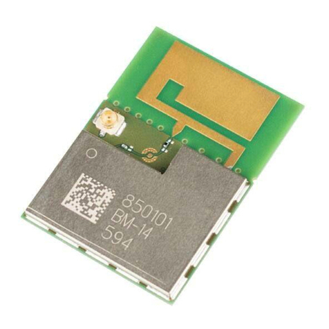
Wiznet WizFi320 User manual

WizFi320 User Manual
© Copyright 2021 WIZnet Co., Ltd. All rights reserved. 1
WizFi320 User Manual
(Version 0.1)
FCC ID : 2AKKW-WIZFI320
© 2021 WIZnet Co., Ltd. All Rights Reserved.
For more information, please visit our website at http://www.wiznet.io/

WizFi320 User Manual
© Copyright 2021 WIZnet Co., Ltd. All rights reserved. 2
Document Revision History
Version Date Revision Description
0.1 2021/06/10 Initial draft

WizFi320 User Manual
© Copyright 2021 WIZnet Co., Ltd. All rights reserved. 3
Contents
1.
Overview ...................................................................................................................................4
2.
Pin Definitions ...........................................................................................................................6
2.1 Pin Layout ....................................................................................................6
2.2 Pin Description.............................................................................................7
3.
Functional Description ..............................................................................................................8
3.1 CPU and Internal Memory ...........................................................................8
3.2 External Flash...............................................................................................8
3.3 Crystal Oscillators ........................................................................................8
3.4 RTC and Low-Power Management ..............................................................8
4.
Electrical Characteristics............................................................................................................9
4.1 Absolute Maximum Ratings.........................................................................9
4.2 Recommended Operating Conditions..........................................................9
4.3 DC Characteristics (3.3 V, 25 °C) ..................................................................9
4.4 Wi-Fi Radio.................................................................................................11
4.5 BLE Radio ...................................................................................................12
4.6 Reflow Profile......................................................................................................13
4.7 Recommended PCB Land Pattern.......................................................................14
5.
testing Guide line ....................................................................................................................15
5.1 Peripheral Circuit Reference Design...................................................................15
5.2 Wi-Fi AT Commands ...........................................................................................16

WizFi320 User Manual
© Copyright 2021 WIZnet Co., Ltd. All rights reserved. 4
1.
Overview
WizFi320 is a powerful, generic Wi-Fi+BT+BLE MCU module that targets a wide
variety of
applications ranging from low-power sensor networks to the most
demanding tasks.
At the core of this module is the ESP32-DOWD-V3 chip. The chip embedded is
designed to be scalable and adaptive. There are two CPU cores that can be
individually controlled, and the CPU clock frequency is adjustable from 80 MHz to
240 MHz. The user may also power off the CPU and make use of the low-power co-
processor to constantly monitor the peripherals for changes or crossing of
thresholds.
The integration of Bluetooth, Bluetooth LE and Wi-Fi ensures that a wide range
of applications can be targeted and that the module is all-around: using Wi-Fi
allows a large physical range and direct connection to the Internet through a
Wi-Fi router, while using Bluetooth allows the user to conveniently connect to
the phone or broadcast low energy beacons for its detection. The sleep current
of the ESP32 chip is less than 5 µA, making it suitable for battery powered and
wearable electronics applications. The module supports a data rate of up to
150Mbps, and 20 dBm output power at the antenna to ensure the widest physical
range. As such the module does offer industry- leading specifications and the
best performance for electronic integration, range, power consumption, and
connectivity.
The operating system chosen for ESP32 is freeRTOS with LwIP; TLS 1.2 with
hardware acceleration is built in as well. Secure (encrypted) over the air (OTA)
upgrade is also supported, so that users can upgrade their products even after
their release, at minimum cost and effort.
Table 1 provides the specifications of WizFi320.
Table 1: WizFi320 Specifications
Categories ltems Specications
Certification
RF certification FCC
Wi-Fi certification Wi-Fi Alliance
Bluetooth certification BQB
Green certification RoHS/REACH
Test Reliablity HTOL/HTSL/uHAST/TCT/ESD
Wi-Fi
Protocols
802.11 b/g/n (802.11n up to 150 Mbps)
A-MPDU and A-MSDU aggregation and 0.4μs guard
interval support
Frequency range 2.4 GHz ~2.5 GHZ
Bluetooth
Protocols Bluetooth v4.2 BR/EDR and BLE specification
Radio
NZIF receiver with -94 dBm sensitivity
Class-1, class-2 and class-3 transmitter

WizFi320 User Manual
© Copyright 2021 WIZnet Co., Ltd. All rights reserved. 5
AFH
Audio CVSD and SBC
Hardware
Module interfaces UART, SPI, SDIO, I²C, I²S, LED PWM, GPIO, ADC,
DAC
On-chip sensor Hall sensor
Integrated crystal 40 MHz crystal
Integrated SPI flash 4MB
Operating voltage/Power supply 3.0 V~3.6V
Operating current Average: 80 mA
Minimum current delivered by power
ul
500 mA
Recommended operating temperature
rn
-40℃~ +85℃
Package size (16±0.10) mm x (24±0.10) mm x (3±0.10) mm
Moisture sensitivity level (MSL) Level 3

WizFi320 User Manual
© Copyright 2021 WIZnet Co., Ltd. All rights reserved. 6
2.
Pin Definitions
2.1 Pin Layout
Figure 1: WizFi320 Pin Layout (Top View)

WizFi320 User Manual
© Copyright 2021 WIZnet Co., Ltd. All rights reserved. 7
2.2 Pin Description
WizFi320 has 38 pins. See pin definitions in Table 2.
Table 2: Pin Definitions
Name No. Type Function
EN 1 I Module-enable signal. Active high.
IO27 2 I/O GPIO27, ADC2_CH7, TOUCH7, RTC_GPIO17, EMAC_RX_DV
IO0 3 I/O PIO0, ADC2_CH1, TOUCH1, RTC_GPIO11, CLK_OUT1, EMAC_TX_CLK
IO25 4 I/O GPIO25, DAC_1, ADC2_CH8, RTC_GPIO6, EMAC_RXD0
IO26 5 I/O GPIO26, DAC_2, ADC2_CH9, RTC_GPIO7, EMAC_RXD1
IO5 6 I/O GPIO5, VSPICS0, HS1_DATA6, EMAC_RX_CLK
IO19 7 I/O GPIO35, ADC1_CH7, RTC_GPIO5
VCC 8 P Power supply
IO15 9 I/O GPIO15, ADC2_CH3, TOUCH3, MTDO, HSPICS0, RTC_GPIO13, HS2_CMD,
SD_CMD, EMAC_RXD3
IO12 10 I/O GPIO12, ADC2_CH5, TOUCH5, RTC_GPIO15, MTDI, HSPIQ, HS2_DATA2,
SD_DATA2, EMAC_TXD3
IO2 11 I/O GPIO2, ADC2_CH2, TOUCH2, RTC_GPIO12, HSPIWP, HS2_DATA0, SD_DATA0
IO4 12 I/O GPIO4, ADC2_CH0, TOUCH0, RTC_GPIO10, HSPIHD, HS2_DATA1, SD_DATA1,
EMAC_TX_ER
IO13 13 I/O GPIO13, ADC2_CH4, TOUCH4, RTC_GPIO14, MTCK, HSPID, HS2_DATA3,
SD_DATA3, EMAC_RX_ER
IO14 14 I/O GPIO14, ADC2_CH6, TOUCH6, RTC_GPIO16, MTMS, HSPICLK, HS2_CLK, SD_CLK,
EMAC_TXD2
GND 15 P Ground
IO22 16 I/O GPIO22, VSPIWP, U0RTS, EMAC_TXD1
TXD0 17 I/O GPIO17, HS1_DATA5, U2TXD, EMAC_CLK_OUT_180
RXD0 18 I/O GPIO16, HS1_DATA4, U2RXD, EMAC_CLK_OUT
IO18 19 I/O GPIO18, VSPICLK, HS1_DATA7
IO23 20 I/O GPIO23, VSPID, HS1_STROBE
RXD1 21 I/O GPIO1, U0TXD, CLK_OUT3, EMAC_RXD2
TXD1 22 I/O GPIO3, U0RXD, CLK_OUT2
WizFi320 User Manual
© Copyright 2021 WIZnet Co., Ltd. All rights reserved. 8
3.
Functional Description
This chapter describes the modules and functions integrated in WizFi320.
3.1 CPU and Internal Memory
ESP32-DOWD-V3 contains two low-power Xtensa® 32-bit LX6 microprocessors. The
internal memory includes:
•
448 KB of ROM for booting and core functions.
•
520 KB of on-chip SRAM for data and instructions.
•
8 KB of SRAM in RTC, which is called RTC FAST Memory and can be used for data
storage; it is
accessed by the main CPU during RTC Boot from the Deep-sleep mode
•
8 KB of SRAM in RTC, which is called RTC SLOW Memory and can be accessed by
the co- processor during the Deep-sleep mode
•
1 Kbit of eFuse: 256 bits are used for the system (MAC address and chip
configuration) and the remaining m768 bits are reserved for customer applications,
including flash-encryption and chip- ID.
3.2 External Flash
WizFi320 integrates a 4 MB SPI flash, which is connected to GPIO6, GPIO7, GPIO8,
GPIO9, GPIO10 and GPIO11 of ESP32.
3.3 Crystal Oscillators
The module uses a 40-MHz crystal oscillator.
3.4 RTC and Low-Power Management
With the use of advanced power-management technologies, ESP32 can switch between
different power modes. For details on
ESP32’s
power consumption in different
power modes, please refer to section
”RTC
and Low-Power
Management”.

WizFi320 User Manual
© Copyright 2021 WIZnet Co., Ltd. All rights reserved. 9
4.
Electrical Characteristics
4.1 Absolute Maximum Ratings
Stresses beyond the absolute maximum ratings listed in Table 3 below may cause
permanent damage to the device. These are stress ratings only, and do not refer
to the functional operation of the device that should follow the recommended
operating conditions.
Table 3: Absolute Maximum Ratings
1.
The module worked properly after a 24-hour test in ambient temperature at
25 °C, and the IOs in three domains (VDD3P3_RTC, VDD3P3_CPU, VDD_SDIO) output
high logic level to ground. Please note that pins occupied by flash and/or
PSRAM in the VDD_SDIO power domain were excluded from the test.
2.
Please see Appendix IO_MUX of ESP32 Datasheet for IO
’
s power domain.
4.2 Recommended Operating Conditions
Table 4: Recommended Operating Conditions
4.3 DC Characteristics (3.3 V, 25 °C)
Table 5: DC Characteristics (3.3 V,
25 °C)
Symbol Parameter Min Max Unit
VDD33 Power supply voltage -0.3 3.6 V
I
Cumulative IO output current - 1200 mA
I
Storage temperature -40 82 °C
Symbol Parameter Min Typical Max Unit
VDD33 Power supply voltage 2.3 3.3 3.6 V
Current delivered by external power supply 0.5 - - A
T
Operating temperature -40 - 85 °C

WizFi320 User Manual
© Copyright 2021 WIZnet Co., Ltd. All rights reserved. 10

WizFi320 User Manual
© Copyright 2021 WIZnet Co., Ltd. All rights reserved. 11
Notes:
1. Please see Appendix IO_MUX of ESP32 Datasheet for
IO’s
power domain. VDD is the I/O
voltage for a
particular power domain of pins.
2. For VDD3P3_CPU and VDD3P3_RTC power domain, per-pin current sourced in the same
domain is gradually reduced from around 40 mA to around 29 mA, V
OH
>=2.64 V, as the number
of current-source pins increases.3. Pins occupied by flash and/or PSRAM in the VDD_SDIO
power domain were excluded from the test.
4.4 Wi-Fi Radio
Table 6: Wi-Fi Radio Characteristics
1.
Device should operate in the frequency range allocated by regional
regulatory authorities. Target operating frequency range is configurable by
software.
2.
For the modules that use IPEX antennas, the output impedance is 50 .
Ω
For
other modules without IPEX antennas, users do not need to concern about the
output impedance.
3.
Target TX power is configurable based on device or certification requirements.
Parameter Condition Min Typical Max Unit
Operatingfrequenc
y
range - 2412 - 2462 MHz
Outputinpedance - - note 2 -
Ω
Txpower
11n, MCS7 12 13 14 dBm
11b mode 18.5 19.5 20.5 dBm
Sensitivity
11b, 1 Mbps - –98 - dBm
11b, 11 Mbps - –88 - dBm
11g, 6 Mbps - –93 - dBm
11g, 54 Mbps - –75 - dBm
11n, HT20, MCS0 - –93 - dBm
11n, HT20, MCS7 - –73 - dBm
11n, HT40, MCS0 - –90 - dBm
11n, HT40, MCS7 - –70 - dBm
Adjacent channel rejection
11g, 6 Mbps - 27 - dB
11g, 54 Mbps - 13 - dB
11n, HT20, MCS0 - 27 - dB
11n, HT20, MCS7 - 12 - dB

WizFi320 User Manual
© Copyright 2021 WIZnet Co., Ltd. All rights reserved. 12
4.5 BLE Radio
4.5.1
Receiver
Table 7: Receiver Characteristics – BLE
4.5.2
Trans
mitter
Table 8: Transmitter Characteristics – BLE
PARAMETER CONDITION MINI VALUE MAX UNIT
Sensitivity @0.1% BER - -90 –89 -88 dBm
Maximum received signal @0.1% BER - 0 - - dBm
Co-channel rejection ratio C/I - - +7 - dB
Adjacent channel rejection ratio C/I
F = F0 + 1 MHz - – -6 dB
F = F0 –1 MHz - – -6 dB
F = F0 + 2 MHz - – -25 dB
F = F0 –2 MHz - – -33 dB
F = F0 + 3 MHz - – -25 dB
F = F0 –3 MHz - – -45 dB
Out-of-band blocking
30 MHz ~ 2000 MHz –10 dBm
2000 MHz ~ 2400 MHz –27 dBm
2500 MHz ~ 3000 MHz –27 dBm
3000 MHz ~ 12.5 GHz –10 dBm
Intermodulation - –36 dBm
PARAMETER CONDITION MINI VALUE MAX UNIT
RF transmit power - - 0 - dBm
Gain control step - - 3 - dB
RF power control range - –12 - +9 dBm
20dB bandwidth - - 0.9 - MHz
Adjacent channel transmit
power
F = F0 ± 2 MHz - –47 - dBm
F = F0 ± 3 MHz - –55 - dBm
F = F0 ± > 3 MHz - –60 - dBm
∆ f1avg - - - 155 kHz
∆ f2max - 133.7 - - kHz
∆ f2avg/∆ f1avg - - 0.92 - -
ICFT - - –7 - kHz
Drift rate - - 0.7 - kHz/50 µs
Offset 6 kHz

WizFi320 User Manual
© Copyright 2021 WIZnet Co., Ltd. All rights reserved. 13
4.6 Reflow Profile
Figure2: Reflow Profile

WizFi320 User Manual
© Copyright 2021 WIZnet Co., Ltd. All rights reserved. 14
4.7 Recommended PCB Land Pattern

WizFi320 User Manual
© Copyright 2021 WIZnet Co., Ltd. All rights reserved. 15
5.
testing Guide line
5.1 Peripheral Circuit Reference Design

WizFi320 User Manual
© Copyright 2021 WIZnet Co., Ltd. All rights reserved. 16
5.2 Wi-Fi AT Commands
• AT+CWMODE: Set the Wi-Fi mode (Station/SoftAP/Station+SoftAP).
• AT+CWSTATE: Query the Wi-Fi state and Wi-Fi information.
• AT+CWJAP: Connect to an AP.
• AT+CWRECONNCFG: Query/Set the Wi-Fi reconnecting configuration.
• AT+CWLAPOPT: Set the configuration for the command AT+CWLAP.
• AT+CWLAP: List available APs.
• AT+CWQAP: Disconnect from an AP.
• AT+CWSAP: Query/Set the configuration of an ESP SoftAP.
• AT+CWLIF: Obtain IP address of the station that connects to an ESP
SoftAP.
• AT+CWQIF: Disconnect stations from an ESP SoftAP.
• AT+CWDHCP: Enable/disable DHCP.
• AT+CWDHCPS: Query/Set the IP addresses allocated by an ESP SoftAP
DHCP server.
• AT+CWAUTOCONN: Connect to an AP automatically when powered on.
• AT+CWAPPROTO: Query/Set the 802.11 b/g/n protocol standard of
SoftAP mode.
• AT+CWSTAPROTO: Query/Set the 802.11 b/g/n protocol standard of
station mode.
• AT+CIPSTAMAC: Query/Set the MAC address of an ESP station.
• AT+CIPAPMAC: Query/Set the MAC address of an ESP SoftAP.
• AT+CIPSTA: Query/Set the IP address of an ESP station.
• AT+CIPAP: Query/Set the IP address of an ESP SoftAP.
• AT+CWSTARTSMART: Start SmartConfig.
• AT+CWSTOPSMART: Stop SmartConfig.
• AT+WPS: Enable the WPS function.
• AT+MDNS: Configure the mDNS function.
• [ESP32 Only] AT+CWJEAP: Connect to a WPA2 Enterprise AP.
• AT+CWHOSTNAME: Query/Set the host name of an ESP station.
• AT+CWCOUNTRY: Query/Set the Wi-Fi Country Code.
AT+CWMODE: Query/Set the Wi-Fi Mode
(Station/SoftAP/Station+SoftAP)
Query Command
Function:

WizFi320 User Manual
© Copyright 2021 WIZnet Co., Ltd. All rights reserved. 17
Query the Wi-Fi mode of ESP devices.
Command:
AT+CWMODE?
Response:
+CWMODE:<mode>
OK
Set Command
Function:
Set the Wi-Fi mode of ESP devices.
Command:
AT+CWMODE=<mode>[,<auto_connect>]
Response:
OK
Parameters
• <mode>:
o 0: Null mode. Wi-Fi RF will be disabled.
o 1: Station mode.
o 2: SoftAP mode.
o 3: SoftAP+Station mode.
• <auto_connect>: Enable or disable automatic connection to an AP when
you change the mode of the ESP device from the SoftAP mode or null
mode to the station mode or the SoftAP+Station mode. Default: 1. If you
omit the parameter, the default value will be used, i.e. automatically
connecting to an AP.
o 0: The ESP device will not automatically connect to an AP.
o 1: The ESP device will automatically connect to an AP if the
configuration to connect to the AP has already been saved in
flash before.
Note
• The configuration changes will be saved in the NVS area
if AT+SYSSTORE=1.

WizFi320 User Manual
© Copyright 2021 WIZnet Co., Ltd. All rights reserved. 18
Example
AT+CWMODE=3
AT+CWSTATE: Query the Wi-Fi state and Wi-Fi
information
Query Command
Function:
Query the Wi-Fi state and Wi-Fi information of ESP devices.
Command:
AT+CWSTATE?
Response:
+CWSTATE:<state>,<"ssid">
OK
Parameters
• <state>: current Wi-Fi state.
o 0: ESP station has not started any Wi-Fi connection.
o 1: ESP station has connected to an AP, but does not get an
IPv4 address yet.
o 2: ESP station has connected to an AP, and got an IPv4
address.
o 3: ESP station is in Wi-Fi connecting or reconnecting state.
o 4: ESP station is in Wi-Fi disconnected state.
• <”ssid”>: the SSID of the target AP.
Note
• When ESP station is not connected to an AP, it is recommended to use
this command to query Wi-Fi information; after ESP station is connected
to an AP, it is recommended to use AT+CWJAP to query Wi-Fi
information.
AT+CWJAP: Connect to an AP
Query Command
Function:
Query the AP to which the ESP Station is already connected.

WizFi320 User Manual
© Copyright 2021 WIZnet Co., Ltd. All rights reserved. 19
Command:
AT+CWJAP?
Response:
+CWJAP:<ssid>,<bssid>,<channel>,<rssi>,<pci_en>,<reconn_interval>,<listen_interval>,
<scan_mode>,<pmf>
OK
Set Command
Function:
Connect an ESP station to a targeted AP.
Command:
AT+CWJAP=[<ssid>],[<pwd>][,<bssid>][,<pci_en>][,<reconn_interval>][,<listen_interval
>][,<scan_mode>][,<jap_timeout>][,<pmf>]
Response:
WIFI CONNECTED
WIFI GOT IP
OK
[WIFI GOT IPv6 LL]
[WIFI GOT IPv6 GL]
or
+CWJAP:<error code>
ERROR
Execute Command
Function:
Connect an ESP station to a targeted AP with last Wi-Fi configuration.
Command:
AT+CWJAP
Response:
WIFI CONNECTED
WIFI GOT IP
OK
[WIFI GOT IPv6 LL]
[WIFI GOT IPv6 GL]
or

WizFi320 User Manual
© Copyright 2021 WIZnet Co., Ltd. All rights reserved. 20
+CWJAP:<error code>
ERROR
Parameters
•
<ssid>: the SSID of the target AP.
o Escape character syntax is needed if SSID or password
contains special characters, such
,
,
"
, or
\\
.
•
<pwd>: password, MAX: 64-byte ASCII.
•
<bssid>: the MAC address of the target AP. It cannot be omitted
when multiple APs have the same SSID.
•
<channel>: channel.
•
<rssi>: signal strength.
•
<pci_en>: PCI Authentication.
o 0: The ESP station will connect APs with all encryption
methods, including OPEN and WEP.
o 1: The ESP station will connect APs with all encryption
methods, except OPEN and WEP.
•
<reconn_interval>: the interval between Wi-Fi reconnections. Unit:
second. Default: 1. Maximum: 7200.
o 0: The ESP station will not reconnect to the AP when
disconnected.
o [1,7200]: The ESP station will reconnect to the AP at the
specified interval when disconnected.
•
<listen_interval>: the interval of listening to the AP’s beacon. Unit:
AP beacon intervals. Default: 3. Range: [1,100].
•
<scan_mode>:
o 0: fast scan. It will end after finding the targeted AP. The ESP
station will connect to the first scanned AP.
o 1: all-channel scan. It will end after all the channels are
scanned. The device will connect to the scanned AP with the
strongest signal.
•
<jap_timeout>: maximum timeout for AT+CWJAP command. Unit:
second. Default: 15. Range: [3,600].
•
<pmf>: Protected Management Frames. Default: 0.
o 0 means disable PMF.
Table of contents
Other Wiznet Wireless Router manuals

Wiznet
Wiznet WizFi360 Series Guide

Wiznet
Wiznet WizFi630S User manual

Wiznet
Wiznet WizFi630 User manual

Wiznet
Wiznet WizFi360 Series Mounting instructions

Wiznet
Wiznet WizFi360 Series Setup guide

Wiznet
Wiznet WizFi360 Series Mounting instructions

Wiznet
Wiznet WizFi630 Installation instructions

Wiznet
Wiznet WizFi210 User manual

Wiznet
Wiznet WIZ630wi User manual

Wiznet
Wiznet WizFi250 Manual