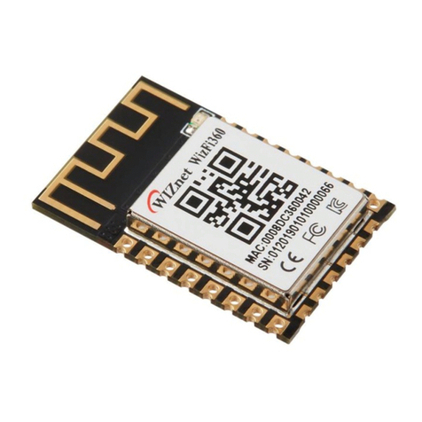
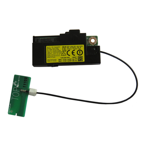
Wiznet WizFi360 Series User manual

User Manual
WizFi360
FCC ID:2ATUB-WIZFI360PA
https://www.iwiznet.cn
Manufacture:WIZnet H.K. LTD.

WizFi360 User Manual
'RFXPHQW 5HYLVLRQ +LVWRU\
Da
te
R
evision
Chan
ges
2019.
04.04
V1.0
O
fficial Release

WizFi360 User Manual
'LVFODLPHU DQG &RS\ULJKW 1RWLFH
The information in this document, including the URL address for reference, is subject to change
without notice. The document is provided "as is" without warranty of any kind, including any
warranties of merchantability, fitness for a particular purpose, or non-infringement, and any
warranties mentioned in the proposal, specification or sample. This document is not responsible for
any liability, including any infringement of any patent rights arising out of the use of the information
in this document. No license, express or implied, by estoppel or otherwise, is hereby granted. The
Wi-Fi Alliance member logo is owned by the Wi-Fi Alliance. All trademark names, trademarks and
registered trademarks mentioned herein are the property of their respective owners and are hereby
acknowledged.

WizFi360 User Manual
&RQWHQWV
9.
RF Power Parameters
.................................................................................................................
13
10.
Command Description
..................................................................................................
14
10.1
%DVLF $7 &RPPDQGV
..............................................................................................................................
15
10.1.1 Overview .............................................................................................................................................
15
10.1.2Commands
..................................................................................................................................
16
10.1.2.1. AT
Tests AT Startup
.............................................................................................
16
10.1.2.2
ˊ
AT+RST
Restarts the Module .....................................................................................
16
10.1.2.3
ˊ
AT+GMR
Checks Version Information .....................................................................
16
10.1.2.4
ˊ
ATE
AT Commands Echoing .......................................................................................
16
10.1.2.5
ˊ
AT+RESTORE
RestorestheFactory DefaultSettings
.............................................
16
10.1.2.6
ˊ
AT+UART
UART Configuration ..............................................................................
17
10.1.2.7
ˊ
AT+UART_CUR
Current UART Configuration;Not Savedin the Flash
..............
18
10.1.2.8
ˊ
AT+UART_DEF
Default UART Configuration; Saved in the Flash
.......................
18
10.1.2.9
ˊ
AT+SYSRAM
Checks the Remaining Space of RAM
..............................................
19
10.1.2.10
᧪
AT+CIOMODE
Configures the Mode of a GPIO
.............................................................
20
10.1.2.11
᧪
AT+CIOWRITE
Configures the Output Level of a GPIO
................................................
20
10.1.2.12
᧪
AT+CIOREAD
Reads the GPIO Input Level
....................................................................
20

WizFi360 User Manual
10.2
Wi-Fi AT Commands
...................................................................................................................
22
10.2.1
Overview
......................................................................................................................
22
10.2.2
Commands
..................................................................................................................
23
10.2.2.1
ˊ
AT+CWMODE Sets the mode( Station/SoftAP/Station+Softap )
.........................
23
10.2.2.2
ˊ
AT+CWMODE_CUR Setsthe Current Wi-Fi mode,Configuration Not Savedin the
Flash
23
10.2.2.3.
AT+CWMODE_DEF Sets the Default Wi-Fi mode; Configuration Saved in the
Flash
24
10.2.2.4.
AT+CWJAP Connects to an AP
..........................................................................
24
10.2.2.5.
AT+CWJAP_CUR Connects to an AP; Configuration Not Saved in the Flash
....
25
10.2.2.6.
AT+CWJAP_DEF Connects to an AP; Configuration Saved in the Flash
............
26
10.2.2.7.
AT+CWLAPOPT Sets the Configuration for the Command AT+CWLAP
..........
26
10.2.2.8.
AT+CWLAP Lists Available APs
...........................................................................
27
10.2.2.9.
AT+CWSAP Configures the WizFi360 SoftAP
....................................................
27
10.2.2.10.
AT+CWSAP_CUR Configuresthe WizFi360 SoftAP; Configuration Not Saved in
the Flash Flash
...................................................................................................
28
10.2.2.11.
AT+CWSAP_DEF Configuresthe WizFi360 SoftAP; Configuration Saved in the
Flash Flash
29
10.2.2.12.
AT+CWLIF IP of Stations to Which the WizFi360 SoftAP is Connected
.............
29
10.2.2.13.
AT+CWQAP Disconnect from the AP
................................................................
30
10.2.2.14.
AT+CWDHCP Enables/Disables DHCP
.............................................................
30

WizFi360 User Manual
10.2.2.15.
AT+CWDHCP_CUR
Enables/Disables DHCP; Configuration Not Saved in the
Flash
30
10.2.2.16. AT+CWDHCP_DEF Enables/Disables DHCP; Configuration Saved in the
Flash
.
31
10.2.2.17.
AT+CIPSTA Sets the Current IP Address of the WizFi360 Station
....................
32
10.2.2.18.
AT+CIPSTA_CUR Sets the Current IP Address of the WizFi360, Configuration
Not Saved in the Flash
...................................................................................................
32
10.2.2.19.
AT+CIPSTA_DEF Sets the Current IP Address of the WizFi360, Configuration
Saved in the Flash
....................................................................................................
33
10.2.2.20.
AT+CIPAP Sets the IP Address of the WizFi360 SoftAP
......................................
33
10.2.2.21.
AT+CIPAP_CUR Sets theIP Address of the WizFi360 SoftAP, Configuration Not
Saved in the Flash
.....................................................................................................
34
10.2.2.22.
AT+CIPAP_DEF Sets the IP Address of the WizFi360 SoftAP, Configuration Saved
in the Flash
34
10.2.2.23.
AT+CIPSTAMAC_CUR Sets the MAC Address of the WizFi360 Station
Configuration Not Saved in the Flash
..........................................................................................
35
10.2.2.24.
AT+CIPSTAMAC_DEF Sets the MAC Address of the WizFi360 Station;
Configuration Saved in the Flash
...........................................................................................
35
10.2.2.25.
AT+CWSTARTSMARTStarts SmartConfig
......................................................
36
10.2.2.26.
AT+CWSTOPSMART Stops SmartConfig
............................................................
36
10.2.2.27.
AT+CWAUTOCONN Auto-Connects to the AP or Not
...........................................
37
10.3
TCP/IP-Related AT Commands
.....................................................................................
38
10.3.1
Overview
...............................................................................................................
38
10.3.2
Commands
...........................................................................................................
38

WizFi360 User Manual
10.3.2.1.
AT+CIPDOMAIN DNS Function
.........................................................................
38
10.3.2.2.
AT+CIPSTART Establishes TCP Connection, UDP Transmission
..................
39
TCP Connection:
.............................................................................................................................
39
10.3.2.3.
AT+CIPSEND
..................................................................................................
40
10.3.2.4.
AT+CIPSENDEX
............................................................................................
41
10.3.2.5.
AT+CIPCLOSE Closes the TCP/UDP Connection
..............................................
41
10.3.2.6.
AT+CIFSR Gets the Local IP Address
................................................................
42
10.3.2.7.
AT+CIPMUX Enable or Disable Multiple Connections
....................................
42
10.3.2.8.
AT+CIPSERVER
Deletes/Creates TCP Server
....................................................
42
10.3.2.9.
AT+CIPMODE Sets Transmission Mode
..............................................................
43
10.3.2.10.
AT+CIPSTO Sets the TCP Server Timeout
..........................................................
43
10.3.2.11.
AT+PING Ping Packets
...........................................................................................
44
10.3.2.12.
AT+CIUPDATE Updates the Software Through Wi-Fi
.....................................
44
10.3.2.13.
AT+CIPDINFO Shows the Remote IP and Port with +IPD
...................................
44
10.3.2.14. +IPD Receives Network Data
..............................................................................
44
10.3.2.15.
AT+CIPSNTPCFG
Sets the Configuration of SNTP
............................................
45
10.3.2.16.
AT+CIPSNTPTIME Checks the SNTP Time
........................................................
45
10.3.2.17. AT+CIPDNS_CUR Sets User-defined DNS Servers; Configuration Not Saved in the
Flash
45

WizFi360 User Manual
10.3.2.18.
AT+CIPDNS_DEF
Sets User-defined DNS Servers; Configuration Saved in the
Flash
46
1.
Introduction
WizFi360 WiFi module is independently developed by WIZnet. The module integrates 32-bit MCU with a main
frequency of up to 80MHz. It supports embedded RTOS,PRNG/SHA1/MD5/RC4/DES/3DES/AES/CRC and other
encryption and decryption protocols.The1 MB Flash and WiFi MAC/BB/RF/PA/LNA universal encryption hardware
accelerator are integrated, and the PCB onboard antenna scheme of 3D BI is adopted.
The module supports IEEE802.11 b/g/n protocol and complete TCP/IP protocol stack. Users can use this module to
add networking functions to existing devices, or to build independent network controllers.
WizFi360 is a complete and self-contained WiFi network solution that can run independently or as a slave host MCU.
The module can be booted directly from internal flash memory when it carries applications and acts as the only
application processor in the device. The built-in cache is conducive to improving system performance and reducing
memoryrequirements.
In another case, when WizFi360 is responsible for the task of WiFi adapter, it can be added to any
microcontroller-based design. The connection is simple and easy, just through SPI/SDIO interface or I2C/UART
interface.

WizFi360 User Manual
2.
Features
•
Support IEEE802.11 b/g/n
•
Integrated 32-bit embedded Cortex-M3 CPU, operating frequency 80MHz, support RTOS
•
Integrated TCP/IP stack
•
Integrated PA/LNA/TR-Switch
•
Integrated encryption hardware accelerator, support PRNG,SHA1,MD5,RC4,DES,3DES,AES,CRC,RSA
•
Integrated2.4GRFtransceiverˈsupport IEEE802.11 protocol
•
Support Wi-Fi WMM/WMM-PS/WPA/WPA2/WPS
•
Support 20/40M Bandwidth
•
Support STBC, Greenfield, Short-GI and reverse transmission;
•
Support AMPDU, AMSDU,RIFS
•
Support STA/AP/STA+AP mode
•
Support AT remote upgrade
•
Support for Smart Config (including Android and iOS devices)
•
Support HSPIǃUARTǃI2CǃI2SǃSDIO2.0ǃ7816 interfaceǃPWMǃGPIO
•
Integrated power supply control circuit
•
Standby power consumption less than10uA
•
Wake up, connect and transmit packets within 2ms

WizFi360 User Manual
15
GND
GND
16
PB10
UA
RT1 RTS
17
PA4
U
ART0 TX
18
PA5
U
ART0 RX
19
PB7
IO
20
PB8
IO
21
PB11
U
ART1 RX
22
PB12
U
ART1 TX
5.
Technical Specification
Table 2 Technical Specifications
Parameter Typ
Unit
Input frequency
2400~2484
MHz
Sensitivty
DSSS,1 Mbps -95 dB
m
CCK,11 Mbps -86 dB
m
OFDM,6 Mbps -89 dB
m
OFDM,54 Mbps -73 dB
m
HT20,MCS0 -89 dB
m
HT20,MCS7 -71 dB
m
HT40,MCS0 -85 dB
m
HT40,MCS7 -68 dB
m
Adjacent Channel restrain
OFDM,6 Mbps 32
dB
OFDM,54 Mbps 15
dB

WizFi360 User Manual
512M-Byte
Block 2
Peripherals
512M-Byte
Block 1
SRAM
512M-Byte
Block 0
Code
HT20,MCS0 29
dB
HT20,MCS7 10
dB
6.
Memory Map
0x5FFF FFFF
0X4000 0000
0X3FFF FFFF
0X2000 0000
0X1FFF FFFF
0X0000 0000
Table 3 Address Space Assignments
Table 4 Peripheral Address Space Assignments
P
eriph
eral
Boot
M
ode=0
Boot
M
ode=1
Address Space Description
ROM
0x00000000~
0x0003FFFF
0x1FF00000~
0x1FF3FFFF
F
irmware
FL
ASH
0x08000000~
0x080FFFFF
0x00000000~
0x000FFFFF
Specific instruction
Memory Space
SRAM
0x20000000~
0
x20027
FFF
0
x
20000000~
0
x20027
FFF
Firmware and
instru
ction memor
y
space
MAC RAM
0x20028000~
0x2003FFFF
0x20028000~
0x2003FFFF
SDIO/H_SPI/UART
data buffer
CONF
IG
0x40000000~
0
x40001
FFF
0
x
40000000~
0
x40001
FFF
0x40000000~0x400001FF
SDIO
0x40000200~0x400002FF
SPI
0x40000300~0x400003FF
SDIO Wrapper
0x40000400~0x400005FF
DMA
0x40000600~0x400006FF
PMU
0x40000700~0x400007FF
Clock and Reset
0x40000800~0x400009FF
0x40000A00~0x400013FF
0x40001400~0x400017FF
0x40001800~0x40001FFF
0x40002000~0x400021FF
FLASH Controller
0x40002200~0x400028FF
RSA
0x40003200~0x400033FF
GPSEC
APB
0x40010000~
0
x
4003C000
0
x
40010000~
0
x
4003C000
0x40010000~0x400101FF
I²C Master
0x40010200~0x400103FF
0x40010400~0x400107FF
SPI Master

WizFi360 User Manual
0x40010800~0x400109FF
UART0
0x40010A00~0x40010BFF
UART1
0x40010C00~0x40010DFF
GPIOA
0x40010E00~0x40010FFF
Timer
0x40011000~0x400111FF
WDOG
0x40011200~0x400113FF
GPIOB
0x40011400~0x400115FF
0x40011600~0x400117FF
0x40011800~0x400119FF
PWM
0x40011A00~0x40011BFF
I²S
0x40011C00~0x40011DFF
7816/UART2
0x40014000~0x4000BFFF
0x4001C000~0x4003BFFF
0x40013C00~0x5FFFFFFF
RSV
7.
Interface Description
Table 5 Interface Description
P
in N
ame
Pin Function Description
HSP
I
PB_15(CS)
Suppor
t SPI protocol, has configurable
data
fr
ame. The maximum data rate is 50Mbp.
PB_16(CK)
PB_17(DI)
PB_18(DO)
PWM
P
B_18(PWM1)
P
B_17(PWM2)
P
B_16(PWM3)
P
B_15(PWM4)
P
B_14(PWM5)
Has 5 PWM generators;
Suppor
t 2 channels input capture (PWM0
and
PWM4);
F
requency range: 3Hz~160KHz;
Du
ty ratio precision: 1/256, Dead-Zone
counter:
8bit;
I2C
PB_11(I²C_SCL)
I²C Controller connects though APB Interface.
PB_12(I²C_DAT)
PB_13(I²C_SCL)
Its supports master mode and configurable
operating
PB_14(I²C_DAT)
frequency˄100K-400K˅ .
UAR
T
UA
RT0:
G
PIOA_4(TXD)
G
PIOA_5(RXD)
UA
RT1:
P
B_12(TXD)
P
B_11(RXD)
A device that can be connected to a UART
inter
face.
downloa
d˖
UA
RT0_TXD,UART0_RXD
Communic
ation˖
UA
RT0_TXD,UART0_RXD
UART1_TXD,UART1_RXD
I2S
Master˖
PA_5(I²S_M_EXTCLK)
Support AMBA APB bus protocol, 32bit single
read/write;

WizFi360 User Manual
PB_8(I²S_M_SCL)
PB_9(I²S_M_SDA)
PB_10(I²S_M_RL)
Slave˖
PB_14(I²S_S_SDA)
PB_15(I²S_S_SCL)
PB_16(I²S_S_RL)
Operates as either Master or Slave, support full
duplex;
Capable of handling 8, 16, 24, 32 bits word size,
sampling frequency is up to 128KHz;
Support Mono and stereo audio data;
Support I²S and MSB justified data format,
support PCM A/B data format;
Support DMA data transfer, word access only.
8.
Ultimate Characteristics
Table 6 ultimate characteristic
Parameter
Sy
m
bol
Min Typ Max
Unit
VDD supply
voltage
VDD
3.0 3.3 3.6
V
Input low voltag
e
VIL
-0.3
0.8
V
Input high voltag
e
VIH
2.0
VDD+
0.3
V
nput capacitanc
e
Cpad
2
pF
output low voltag
e
VOL
0.4
V
output hig
h voltage
VOH
2.4
V
Max. output curre
nt
IMAX
24
mA
Storage temper
ature
TSTR
-40
+125
ć
Op
erating tempera
ture
TOPR
-40
+85
ć
9.
RF Power Parameters
Table 7 RF power parameters
Operation Mode Typ
Unit
transmit IEEE802.11b, CCK 11Mbps,
POUT = +19 dBm
230
mA
transmit IEEE802.11g, OFDM 54Mbps,
POUT = +13.5 dBm
210
mA
transmit IEEE802.11n, OFDM MCS7,
POUT = +12dBm
210
mA
re
ceive IEEE802.11b/g/n 100-110 mA

WizFi360 User Manual
10.
Command Description
Each command set contains four types of AT commands
Type
C
ommand Form
at
Description
Te
st Command
A
T+<x>=?
Qu
eries the Set Commands’internal parameters and
thei
r range of values.
Qu
ery
Command
A
T+<x>?
Return
s the current value of parameters.
Set Command
A
T+<x>=<...>
Set
s the value of user-defined parameters in comm
ands,
an
d runs these commands.
E
xecute
Command
A
T+<x>
Runs
commands with no user-defined parameters.
Notice:
•
Not all AT commands support all four variations mentioned above.
•
Square brackets [ ] designate the default value; it is either not required or may not appear.
•
String values need to be included in double quotation marks, for example:AT+CWSAP=
“WizFi360”, “WizFi360”,1,4.
•
The default baud rate is 115200
•
AT commands have to be capitalized, and must end with a new line (CR LF).

WizFi360 User Manual
10.1
%DVLF
$7 &RPPDQGV
10.1.1 Overview
No.
Commands Description
1
AT
T
ests AT startup.
2
AT+R S T
Restart
s the module
3
AT+GMR
Check
s version information.
4
ATE
Confi
gures echoing of AT commands.
5
AT + R ES TO R E
Restores
the factory default settings of the module.
6
AT+UART
UA
RT configuration.
7
AT+UAR
T_CUR
Th
e current UART configuration.
8
AT+UART_DE
F
Th
e default UART configuration, saved in flash.
9
AT+SYSRAM
Check
s the available RAM size.
10
AT+CIOMODE
Confi
gures the mode of GPIO.
11
AT +C I OW R IT E
Confi
gures the GPIO output level
12
AT+CIOREAD
Check
s the GPIO input level.

WizFi360 User Manual
10.1. 2 Commands
10.1.2.1. AT Tests AT Startup
Execut
e Co
mmand
AT
Response
OK
Parameters
-
10.1.2.2
ˊ
AT+RST
Restarts the Module
Execut
e Co
mmand
A
T+RST
Response
OK
Parameters
-
10.1.2.3
ˊ
AT+GMR
Checks Version Information
Execut
e Co
mmand
A
T+GMR
Response
<AT version info>
<SD
K version info>
<compil
e time>
OK
Parameters
•
<AT version info>˖information about the AT version.
•
<SDK version info>˖information about the SDK version.
•
<compile time>˖the duration of time for compiling the BIN.
10.1.2.4
ˊ
ATE
AT Commands Echoing
Execut
e Co
mmand
A
TE
Response
OK
Parameters
•
ATE0˖echo off.
•
ATE1˖echo on.
10.1.2.5
ˊ
AT+RESTORE
Restores the Factory Default
Settings

WizFi360 User Manual
Execut
e Co
mmand
A
T+RESTORE
Response
OK
Note
The execution of this command will reset all parameters saved in flash,
an
d restore the factory default settings of the module. The chip will
be
restarted when this command is executed.
10.1.2.6
ˊ
AT+UART
UART Configuration
Execut
e Co
mmand
A
T+UART?
AT+UART=<baudrate>,<databits>,<st
opbits>,<parity>,<flow control>
Response
+UART:<baudrate>,<databits>,
<stopbits>,<pari
ty>,<flow
control>
OK
OK
Parameters
•
<baudrate>:UART baud rate
•
<databits>: data bits
▶ 5: 5 bit data
▶ 6: 6 bit data
▶ 7: 7 bit data
▶ 8: 8 bit data
•
<stopbits>: stop bits
▶ 1: 1bit stop bits
▶ 2: 2bit stop bits
•
<parity>: parity bit
▶ 0: None
▶ 1: Odd
▶ 2: Even
•
<flow control>: flow control
▶ 0: flow control is not enabled
▶
1: enable both RTS and CTS
Note
•
Command AT+UART? will return the actual value of UART
configuration parameters, which may have allowable errors
compared
with the set value because of the clock division.For example, if
the
UART baud rate is set as 115200, the baud rate returned by using
command AT+UART_CUR? could be 115273.
•
The configuration changes will be saved in the user parameter area
in
the flash, and will still be valid when the chip is powered on again.
•
The range of baud rates supported˖2000000ˈ15
00000ˈ1250000ˈ
1000000ˈ921600ˈ406800ˈ230400ˈ115200ˈ57600ˈ38400ˈ
19200ˈ
9600ˈ4800ˈ2400ˈ1800ˈ1200ˈ600

WizFi360 User Manual
Execut
e Co
mmand
A
T+UART_CUR?
AT+UART_CUR=<baudrate>,<databit
s>,<stopbits>,<parity>,<flow control>
Response
+UART_CUR:<baudrate>,<data
bits>,<stopbits>,
<parity>
,<flow
control>
OK
OK
Parameters
•
<baudrate>:UART baud rate
•
<databits>: data bits
▶ 5: 5 bit data
▶ 6: 6 bit data
▶ 7: 7 bit data
▶ 8: 8 bit data
•
<stopbits>: stop bits
▶ 1: 1bit stop bits
▶ 2: 2bit stop bits
•
<parity>: parity bit
▶ 0: None
▶ 1: Odd
▶ 2: Even
•
<flow control>: flow control
▶ 0: flow control is not enabled
▶
1: enable both RTS and CTS
Notes
•
AT+UART_CUR? will return the actual value of UART configuration
parameters, which may have allowable errors compared with the
set
value because of the clock division.For example, if the UART
baud
rate is set as 115200, the baud rate returned by using command
AT+UART_CUR? could be 115273.
•
The range of baud rates supported˖2000000ˈ15
00000ˈ1250000ˈ
1000000ˈ921600ˈ406800ˈ230400ˈ115200ˈ57600ˈ38400ˈ
19200ˈ
9600ˈ4800ˈ2400ˈ1800ˈ1200ˈ600
Example
A
T+UART_CUR=115200,8,1,0,0
Example AT+UART=115200,8,1,0,0
10.1.2.7
ˊ
AT+UART_CUR
Current UART
Configuration; Not Saved in the
Flash
10.1.2.8
ˊ
AT+UART_DEF
Default UART Configuration;
Saved in the
Flash

WizFi360 User Manual
Execut
e Co
mmand
AT+UART_DEF?
AT+UART_DEF=<baudrate>,<databits
>,<stopbits>,<parity>,<flow control>
Response
+UART_DEF:<baudrate>,<data
bits>,<stopbits>,
<parity>
,<flow
control>
OK
OK
Parameters
•
<baudrate>:UART baud rate
•
<databits>: data bits
▶ 5: 5 bit data
▶ 6: 6 bit data
▶ 7: 7 bit data
▶ 8: 8 bit data
•
<stopbits>: stop bits
▶ 1: 1bit stop bits
▶ 2: 2bit stop bits
•
<parity>: parity bit
▶ 0: None
▶ 1: Odd
▶ 2: Even
•
<flow control>: flow control
▶ 0: flow control is not enabled
▶
1: enable both RTS and CTS
Notes
•
AT+UART_DEF? will return the actual value of UART configuration
parameters, which may have allowable errors compared with the
set
value because of the clock division.For example, if the UART
baud
rate is set as 115200, the baud rate returned by using command
AT+UART_CUR? could be 115273.
•
The configuration changes will be saved in the user parameter area
in
the flash, and will still be valid when the chip is powered on ag
ain.
•
The range of baud rates supported˖2000000ˈ15
00000ˈ1250000ˈ
1000000ˈ921600ˈ406800ˈ230400ˈ115200ˈ57600ˈ38400ˈ
19200ˈ
9600ˈ4800ˈ2400ˈ1800ˈ1200ˈ600
Example
A
T+UART_DEF=115200,8,1,0,0
10.1.2.9
ˊ
AT+SYSRAM
Checksthe RemainingSpace of
RAM
Execut
e Co
mmand
A
T+SYSRAM˛
Response
+SYSRAM:<RAM
> OK
Parameters
<
RAM>˖remaining space of RAM, unit: byte.

WizFi360 User Manual
Example AT+SYSRAM?
10.1.2.10 ˊAT+CIOMODE Configures the Mode of a
GPIO
Execute Co
mmand
A
T+CIOMODE=<pin>,<mode>
Response
OK
Parameters
•
<mode>˖Operating mode
-1˖sets the GPIO as an output
-0˖sets the GPIO as an input
Example
A
T+CIOMODE=6,1
10.1.2.11 ˊAT+CIOWRITE Configures the Output Level
of a GPIO
Execute Co
mmand
A
T+CIOWRITE=<pin>,<level>
Response
OK
Parameters
•
<level>˖
-1˖high level
-0˖low level
Example
AT+CIOMODE=6,1
AT+CIOWRITE=6,0
10.1.2.12 ˊAT+CIOREADReads the GPIO Input Level
Execute Co
mmand
A
T+CIOREAD=<pin>
Other manuals for WizFi360 Series
8
Table of contents
Other Wiznet Wireless Router manuals

Wiznet
Wiznet WizFi630 User manual

Wiznet
Wiznet WizFi630 Installation instructions

Wiznet
Wiznet WizFi320 User manual

Wiznet
Wiznet WizFi360 Series Mounting instructions

Wiznet
Wiznet WizFi210 User manual

Wiznet
Wiznet WizFi360 Series Guide

Wiznet
Wiznet WIZ630wi User manual

Wiznet
Wiznet WizFi360 Series Mounting instructions

Wiznet
Wiznet WizFi630S User manual

Wiznet
Wiznet WizFi360 Series Setup guide