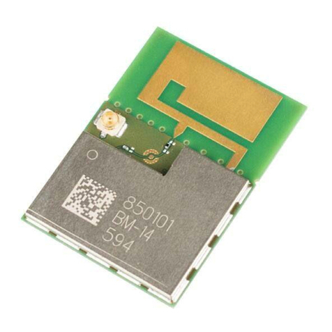
Wiznet WizFi210 User manual

WizFi210/220 User Manual (WIZnet Co., Ltd.)
Certification Information
CE for Class B ITE
INFORMATION TO THE USER
Hereby, WIZnet. Declares that these WizFi210 and WizFi220 are in compliance with the
essential requirements
and other relevant provisions of directive 1999/5/EC.
WARNING: These are the class B products. In a domestic environment this product may cause
radio interference in which case the user may be required to take adequate measures.
FCC for Class B ITE
INFORMATION TO THE USER
These equipments have been tested and found to comply with the limits for a Class B digital
device, pursuant to part 15 of the FCC Rules. These limits are designed to provide reasonable
protection against harmful interference in a residential installation. This equipment generates,
uses and can radiate radio frequency energy and, if not installed and used in accordance with
the instructions, may cause harmful interference to radio communications. However, there is no
Guarantee that interference will not occur in a particular installation. If this equipment does
cause harmful interference to radio or television reception, which can be determined by turning
the equipment off and on, the user is encouraged to try to correct the interference by one more
of the following measures:
-Reorient or relocate the receiving antenna.
-Increase the separation between the equipment and receiver.
-Connect the equipment into an outlet on a circuit different from that to which the
receiver is connected.
- Consult the dealer or an experienced radio/TV technician for help.
WARNING: These equipments may generate or use radio frequency energy. Changes or
modifications to this equipment may cause harmful interference unless the modifications are
expressly approved in the instruction manual. The user could lose the authority to operate this
equipment if an unauthorized change or modification is made.
KC for Class B ITE
INFORMATION TO THE USER
This equipment has been tested for a Class B digital device.
-Trade Name or Applicant : WIZnet, Co., Ltd.
-Equipment Name : Wireless LAN Module
-Model Number : WizFi210 / WizFi220
-Manufacturer / Country of Origin : WIZnet, Co., Ltd. / KOREA
-Certification Number : KCC-CRM-WWW-WIZFI210 / KCC-CRM-WWW-WIZFI220
WARNING: This equipment may generate or use radio frequency energy. Changes or
modifications to this equipment may cause harmful interference.

WizFi210/220 User Manual (WIZnet Co., Ltd.)
Document Revision History
Date Revision Changes
2011-03-24 V1.0 Official Release
2011-05-24 V1.01
Changed Power Consumption and RF Output Power
Added Auto Reconnect AT Command(AT+XAR)
Added Certification Information
2011-09-05 V1.10
Changed Evaluation Board
Changed GPIO number(HW Trigger, Button)
Changed AT+XEHT Command
Added Limited AP Feature
Added WizFi220 Specs
2012-01-11 V1.11
Added UART baud rate(460800, 921600)
Added EXT_RESET description
Added FAQ
Added AT+DHCPSRVR Command
Added Product contents
2012-10-24 V1.12
Added AT+WAUTO Option(2 for Limited AP mode)
Added FAQ(Reducing the disassociation event)
Removed unused AT Commands
Removed some features for customizing f/w

WizFi210/220 User Manual (WIZnet Co., Ltd.)
<Contents>
1. Overview .......................................................................................................................... 1
(1) Benefits and Features ............................................................................................... 2
(2) Specifications............................................................................................................ 3
(3) Product contents (WizFi2x0-EVB).............................................................................. 3
2. Hardware Specification .................................................................................................... 4
(1) Operating Conditions ............................................................................................... 4
(2) Digital Input Specifications ....................................................................................... 4
(3) Digital Output Specifications .................................................................................... 4
(4) I/O Digital Specification (Tri-State)............................................................................ 5
(5) RTC Input Specifications ........................................................................................... 6
(6) RTC Output Specifications ........................................................................................ 6
(7) Internal 1.8V regulator.............................................................................................. 6
(8) Power Consumption (VDDRTC=VDD=3.3V, VDDIO=1.8V, Temp=25°C)..................... 7
(9) Power Consumption (VDDRTC=VDD=3.3V, VDDIO=3.3V, Temp=25°C)..................... 7
(10) Power Consumption (VDDRTC=VDD=3.3V, VDDIO=1.8V, Temp=25°C)............... 8
(11) Power Consumption (VDDRTC=VDD=3.3V, VDDIO=3.3V, Temp=25°C)............... 8
(12) RF Specification .................................................................................................. 9
(13) Block Diagram .................................................................................................. 10
(14) Pin Description ................................................................................................. 11
(15) Module Dimension ........................................................................................... 15
(16) Recommend Pad Dimension............................................................................. 16
(17) LED Indications ................................................................................................. 17
(18) Application Circuit ............................................................................................ 18
(19) Interface ........................................................................................................... 19
(20) Using EXT_RESET pin ........................................................................................ 20
3. Application Guide .......................................................................................................... 21
(1) AP Scanning ........................................................................................................... 21
(2) Network Connection Management......................................................................... 21
(3) Auto Connection Operation.................................................................................... 21
(4) Response Codes ..................................................................................................... 23
(5) Use of GPIO21 ........................................................................................................ 24
(6) AT Command example ........................................................................................... 24
4. AT Commands ............................................................................................................... 26
(1) Command interface ................................................................................................ 26
(2) UART / adapter interface configuration.................................................................. 26
(3) Profile management ............................................................................................... 27
(4) Wi-Fi interface ........................................................................................................ 28
(5) Wi-Fi security.......................................................................................................... 29
(6) Wireless configuration ............................................................................................ 30
(7) Network interface ................................................................................................... 30
(8) Connection management ....................................................................................... 31
(9) Battery check .......................................................................................................... 32
(10) Power state management................................................................................. 32
(11) Auto connection ............................................................................................... 33
(12) Provisioning ...................................................................................................... 33
(13) Miscellaneous ................................................................................................... 33
5. FAQ ................................................................................................................................ 35
6. Warranty ........................................................................................................................ 38
WizFi210/220 User Manual (WIZnet Co., Ltd.)
<Table>
TABLE 1. SPECIFICATIONS......................................................................................................................................3
TABLE 2. OPERATING CONDITIONS...................................................................................................................4
TABLE 3. DIGITAL INPUT SPECIFICATIONS....................................................................................................4
TABLE 4. DIGITAL OUTPUT SPECIFICATIONS...............................................................................................4
TABLE 5. I/O DIGITAL SPECIFICATION...............................................................................................................5
TABLE 6. RTC INPUT SPECIFICATIONS............................................................................................................6
TABLE 7. RTC OUTPUT SPECIFICATIONS.......................................................................................................6
TABLE 8. INTERNAL 1.8V REGULATOR.............................................................................................................6
TABLE 9. POWER CONSUMPTION 1...................................................................................................................7
TABLE 10. POWER CONSUMPTION 2 ................................................................................................................7
TABLE 11. POWER CONSUMPTION 3.................................................................................................................8
TABLE 12. POWER CONSUMPTION 4................................................................................................................8
TABLE 13. RF SPECIFICATION...............................................................................................................................9
TABLE 14. PIN DESCRIPTION.............................................................................................................................. 14
TABLE 15. LED INDICATIONS............................................................................................................................... 17
TABLE 16. RESPONSE CODES........................................................................................................................... 23
TABLE 17. AT COMMAND EXAMPLE................................................................................................................. 25
TABLE 18. COMMAND INTERFACE................................................................................................................... 26
TABLE 19. UART /ADAPTER INTERFACE CONFIGURATION.............................................................. 27
TABLE 20. PROFILE MANAGEMENT................................................................................................................. 27
TABLE 21. WI-FI INTERFACE................................................................................................................................ 29
TABLE 22. WI-FI SECURITY................................................................................................................................... 30
TABLE 23. WIRELESS CONFIGURATION....................................................................................................... 30
TABLE 24. NETWORK INTERFACE.................................................................................................................... 31
TABLE 25. CONNECTION MANAGEMENT..................................................................................................... 32
TABLE 26. BATTERY CHECK ................................................................................................................................ 32
TABLE 27. POWER STATE MANAGEMENT................................................................................................... 32
TABLE 28. AUTO CONNECTION.......................................................................................................................... 33
TABLE 29. PROVISIONING..................................................................................................................................... 33
TABLE 30. MISCELLANEOUS ............................................................................................................................... 34

WizFi210/220 User Manual (WIZnet Co., Ltd.)
<Figure>
FIGURE 1. BASIC DIAGRAM ....................................................................................................................................1
FIGURE 2. WIZFI210 BLOCK DIAGRAM.......................................................................................................... 10
FIGURE 3. WIZFI220 BLOCK DIAGRAM.......................................................................................................... 10
FIGURE 4. PIN DESCRIPTION.............................................................................................................................. 11
FIGURE 5. MODULE DIMENSION....................................................................................................................... 15
FIGURE 6. RECOMMEND PAD DIMENSION................................................................................................. 16
FIGURE 7. VIN = BATTERY, STANDBY MODE SUPPORT........................................................................ 18
FIGURE 8. VIN = DC ADAPTOR, ALWAYS ACTIVE...................................................................................... 18
FIGURE 9. WIZFI2Z0 EVB INTERFACE............................................................................................................ 19
FIGURE 10. USING EXT_RESET PIN................................................................................................................ 20
FIGURE 11. FACTORY DEFAULT AND AD HOC MODE............................................................................ 24

WizFi 210/220 User Manual (WIZnet Co., Ltd.)
1
1. Overview
The WizFi210 family of fully certified modules offers a quick, easy, and cost effective way for
device and appliance manufacturers to add Wi-Fi capabilities to their products. The module
provides serial UART interface which enables connection to any embedded design utilizing
an 8/16/32-bit microcontroller via simple commands. The WizFi210 is an ideal solution for
organizations with limited or no Wi-Fi or RF expertise, as it not only dramatically reduces RF
design time but also removes the burden of testing and certification; allowing customers to
focus on their core application, product, or expertise. The module supports data rates up to
11 Mbps, and is compliant with 802.11b.
The WizFi210 provides customers the mean to evaluate the capabilities of ultra-low power
wireless system-on-a-chip and the Serial to Wi-Fi embedded software for Wi-Fi networks.
The Serial to Wi-Fi embedded software allows devices and appliance manufacturers to easily
add Wi-Fi capabilities to their products with minor impact on the host microcontroller
firmware.
The WizFi210 provides all the hardware and software necessary to quickly set up a serial
(UART) based link to a PC or external microcontroller.
The WizFi220 is a RF-enhanced Product. Except for [RF Output Power], the WizFi220 is
similar in management and development to the WizFi210. In other words, the WizFi220 will
consume more power but it has the improved WiFi range.
(All documents for the WizFi210 apply to the WizFi220)
Figure 1. Basic Diagram

WizFi 210/220 User Manual (WIZnet Co., Ltd.)
2
(1) Benefits and Features
Brings Wi-Fi connectivity to any device with a microcontroller and serial HOST
interface (UART)
Minimal Serial to Wi-Fi “driver” footprint on host microcontroller and minor
changes to existing host MCU firmware
Offloading of smaller host microcontrollers from the Wi-Fi and TCP/ IP networking
Simple AT commands for configuration and data communication
DHCP/Static IP, TCP/UDP, Server/Client, DNS
Reduces development time, testing and certification burden, accelerating time to
market
Easy device provisioning through our utility or Wi-Fi Protected Set-up (WPS)
Ultra low power consumption through dynamic power management
Operates with standard 802.11 b/g/n access points at speed up to 11 Mbps
(802.11b)
802.11i Security (WEP, WPA, WPA2-PSK, Enterprise)
Rich I/O interfaces (SPI, UART, GPIO, I2C, ADC, JTAG)
Low power modes, Alarm Input for wake-up
High-throughput hardware AES and RC4 encryption/decryption engines
Limited AP Feature (Direct Connection to iPhone, iPad and Android-Phone without
AP)

WizFi 210/220 User Manual (WIZnet Co., Ltd.)
3
(2) Specifications
Specifications Description
Radio Protocol IEEE 802.11b/g/n Compatible
Supported Data Rates 11, 5.5, 2, 1 Mbps (802.11 b)
Modulation DSSS and CCK
RF Operating Frequency 2.4 - 2.497 GHz
Antenna Options Chip antenna and U.FL connector for external antenna
Networking Protocols UDP, TCP/IP (IPv4), DHCP, ARP, DNS, HTTP/HTTPS Client and
Server(**)
Power Consumption
(Typical)
Standby = 34.0 µA(WizFi210), 35.0 µA(WizFi220)
Receive = 125.0 mA(WizFi210), 125.0 mA(WizFi220)
Transmit = 135.0 mA(WizFi210), 250.0 mA(WizFi220)
RF Output Power (Typical) 8± 1 dBm (WizFi210)
17 ± 1.5 dBm (WizFi220)
Security Protocols W E P, WPA/WPA2–PSK, Enterprise(EAP-FAST, EAP-TLS, EAP-
TTLS, PEAP)(**)
I/O Interface UART, SPI(**), I2C(*), WAKE, ALARM, GPIOs
Power Source 3.3V
Dimensions 32 x 23.5 x 3 mm
Table 1. Specifications
(*) is supported by software customizing.
(**) is supported by dedicated firmware.
(3) Product contents (WizFi2x0-EVB)
WizFi 2x0 Module + Interface Board + Base Board
Serial Cable / 1EA
USB Cable / 1EA
Antenna(W5I-BO-07) / 1EA : for WizFi2x0-CO(connector) version

WizFi 210/220 User Manual (WIZnet Co., Ltd.)
4
2. Hardware Specification
(1) Operating Conditions
Min Typ Max Unit
Operating Ambient Range -40 +85 °C
RTC Supply Voltage 1.2 3.3 3.6 V
Single Supply Voltage 3.0 3.3 3.6 V
Table 2. Operating Conditions
(2) Digital Input Specifications
Min Typ Max Unit
IO Supply Voltage 1.62/3 1.8/3.3 1.98/3.63 V
Input Low Voltage (VIL) -0.3 0.25VDDIO V
Input High Voltage (VIH) 0.8VDDIO VDDIO V
Schmitt trig. Low to High threshold point (VT+) 1.5 V
Schmitt trig. High to Low threshold point (VT-) 1 V
Table 3. Digital Input Specifications
(3) Digital Output Specifications
Min Typ Max Unit
IO Supply Voltage 1.62/3 1.8/3.3 1.98/3.63 V
Output Low Voltage (VIL) 0 0.4 V
Output High Voltage (VIH) 1.3 VDDIO V
Output rise time (tTLH) 7 ns
Output fall time (tTHL) 7 ns
Table 4. Digital Output Specifications

WizFi 210/220 User Manual (WIZnet Co., Ltd.)
5
(4) I/O Digital Specification (Tri-State)
Min Typ Max Unit
IO Supply Voltage 1.62/3 1.8/3.3 1.98/3.63
Input Low Voltage (VIL) -0.3 0.25VDDIO V
Input High Voltage (VIH) 0.8VDDIO VDDIO V
Schmitt trig. Low to High threshold
point (VT+) 1.5 V
Schmitt trig. High to Low threshold
point (VT-) 1 V
Pull-Up Resistor (Ru) 0.05 1 MΩ
Pull-Down Resistor (Rd) 0.05 1 V
Output Low Voltage (VOL) 0 0.4 V
Output High Voltage (VOH) 1.3 VDDIO V
Output rise time @ 3.3V (tToLH) 7 ns
Output fall time @ 3.3V (tToHL) 7 ns
Input rise time (tTiLH) 7 ns
Input fall time (tTiHL) 7 ns
Table 5. I/O Digital Specification

WizFi 210/220 User Manual (WIZnet Co., Ltd.)
6
(5) RTC Input Specifications
Min Typ Max Unit
RTC Supply Voltage (VDDRTC) 1.2 3.6 V
Input Low Voltage (VIL) -0.3 0.25VDDRTC V
Input High Voltage (VIH) 0.8VDDRTC VDDRTC V
Schmitt trig. Low to High threshold
point (VT+) 0.57VDDRTC 0.68VDDRTC V
Schmitt trig. High to Low threshold
point (VT-) 0.27VDDRTC 0.35VDDRTC V
Table 6. RTC Input Specifications
(6) RTC Output Specifications
Min Typ Max Unit
RTC Supply Voltage (VDDRTC) 1.2 3.6 V
Output Low Voltage (VOL) 0 0.4 V
Output High Voltage (VOH) 0.8VDDRTC VDDRTC V
Output rise time (tTLH) 19 142 ns
Output fall time (tTHL) 21 195 ns
Table 7. RTC Output Specifications
(7) Internal 1.8V regulator
Min Typ Max Unit
Output Voltage (VOUT_1V8) 1.8 V
Maximum Output Current (IVOUT_1V8) 250 300 mA
1.8V Regulator Enable "H" Voltage
(EN_1V8) 1.0 VIN_3V3 V
1.8V Regulator Enable "L" Voltage
(EN_1V8) 0 0.25 V
Table 8. Internal 1.8V regulator

WizFi 210/220 User Manual (WIZnet Co., Ltd.)
7
(8) Power Consumption (VDDRTC=VDD=3.3V, VDDIO=1.8V, Temp=25°C)
WizFi 210 Min Type Max Unit
Standby mode
(Only VDDRTC is active) 35 50 µA
Idle mode
(CPU running, WLAN disconnected) 10 mA
Receive
(-81dBm RX sensitivity) 125 130 mA
Transmit
(+8dBm at antenna port) 135 140 mA
Table 9. Power Consumption 1
(9) Power Consumption (VDDRTC=VDD=3.3V, VDDIO=3.3V, Temp=25°C)
WizFi 210 Min Type Max Unit
Standby mode
(Only VDDRTC is active) 35 50 µA
Idle mode
(CPU running, WLAN disconnected) 11 mA
Receive
(-81dBm RX sensitivity) 125 130 mA
Transmit
(+8dBm at antenna port) 135 140 mA
Table 10. Power Consumption 2

WizFi 210/220 User Manual (WIZnet Co., Ltd.)
8
(10) Power Consumption (VDDRTC=VDD=3.3V, VDDIO=1.8V, Temp=25°C)
WizFi 220 Min Type Max Unit
Standby mode
(Only VDDRTC is active) 35 50 µA
Idle mode
(CPU running, WLAN disconnected) 12 mA
Receive
(-81dBm RX sensitivity) 125 130 mA
Transmit
(+8dBm at antenna port) 250 260 mA
Table 11. Power Consumption 3
(11) Power Consumption (VDDRTC=VDD=3.3V, VDDIO=3.3V, Temp=25°C)
WizFi 220 Min Type Max Unit
Standby mode
(Only VDDRTC is active) 35 50 µA
Idle mode
(CPU running, WLAN disconnected) 13 mA
Receive
(-81dBm RX sensitivity) 125 130 mA
Transmit
(+8dBm at antenna port) 250 260 mA
Table 12. Power Consumption 4

WizFi 210/220 User Manual (WIZnet Co., Ltd.)
9
(12) RF Specification
Specification Description
Modulation Technique DSSS for 1, 2Mbps
CCK for 5.5, 11Mbps
Data Rate IEEE 802.11b: 1, 2, 5.5 and 11Mbps
Receive Sensitivity(*)
-84dBm ± 1dB @ 11Mbps
-88dBm ± 1dB @ 5.5Mbps
-90dBm ± 1dB @ 2Mbps
-94dBm ± 1dB @ 1Mbps
Transmit power(*) (Average) WizFi 210 : 8dBm ± 1dB @ 11Mbps
WizFi 220 : 17dBm ± 1.5dB @ 11Mbps
Frequency Range
USA: 2.400 ~ 2.483GHz
Europe: 2.400 ~ 2.483GHz
Japan: 2.400 ~ 2.497GHz
China: 2.400 ~ 2.483GHz
Operating Channels
USA/Canada: 11 (1~11)
Major Europe Countries: 13 (1~13)
France: 4 (10~13)
Japan: 14 for IEEE 802.11b (1~13 or 14th),
13 for IEEE 802.11g (1~13)
Korea/China: 13 (1~13)
Antenna
U.FL External Antenna Support(CON)
External Antenna Pad Support(EX)
Chip Antenna (Optional) (CA)
Table 13. RF Specification
(*) applies to only WizFi2x0-CON(U.FL Connector version)

WizFi 210/220 User Manual (WIZnet Co., Ltd.)
10
(13) Block Diagram
Figure 2. WizFi210 Block Diagram
Figure 3. WizFi220 Block Diagram

WizFi 210/220 User Manual (WIZnet Co., Ltd.)
11
(14) Pin Description
Figure 4. Pin description
1
2
3
4
5
6
7
8
9
10
11
12
13
14
15
16
17
18
49
48
47
46
45
44
43
42
41
40
39
38
37
36
35
34
33
32
31
19
20
21
22
23
24
25
26
27
28
29
30
EXT-ANT
GND
GPIO28
GPIO29
GPIO30
GPIO31
UART0_CTS/GPIO24
UART0_RX/GPIO0
UART0_RTS/GPIO25
UART0_TX/GPIO1
UART1_TX/GPIO2
UART1_RX/GPIO3
UART1_RTS/GPIO27
UART1_CTS/GPIO26
EXT_RESETN
VDDIO
EN_1V8
VIN_3V3
GND
MSPI_CS0/GPIO4
MSPI_CS1/GPIO13
I2C_CLK/GPIO9
PWM0/GPIO10
GPIO19/CLK_44MHz
GPIO20/CLK_22MHz
GPIO21/CLK_11MHz
I2C_DATA/GPIO8
SSPI_MISO
SSPI_CLK
SSPI_CS
SSPI_MOSI
GND
JTAG_TCK
JTAG_TDO
JTAG_TDI
JTAG_TMS
JTAG_NTRST
ALARM1
RTC_OUT1
VBAT
DC_DC_CNTL
ALARM2
ADC1
ADC2
MSPI_MISO/GPIO6
MSPI_MOSI/GPIO7
MSPI_CLK/GPIO5
VOUT_1V8
GND
TOP VIEW

WizFi 210/220 User Manual (WIZnet Co., Ltd.)
12
PIN NAME I/
O IN BIAS DESCRIPTION
1 GND P NA Ground
2 JTAG_TCK (*) I Pull-up Joint Test Action Group Test Clock
3 JTAG_TDO (*) O NA Joint Test Action Group Test Data Out
4 JTAG_TDI (*) I NA Joint Test Action Group Test Data In
It should not be left floating
5 JTAG_TMS (*) I Pull-up Joint Test Action Group Test Mode Select
6 JTAG_NTRST (*) I Pull-up Joint Test Action Group Test Mode Reset
Active Low
7 ALARM1 I NA Embedded Real Time Clock Wake Up Input
1
8 RTC_OUT1 (*) O NA Embedded Real Time Clock Wake Up
Output 1
9 VBAT P NA Embedded Real Time Clock Power Supply
10 DC_DC_CNTL O NA VIN_3V3 Regulator Control Output
11 ALARM2 (*) I NA Embedded Real Time Clock Wake Up Input
2
12 ADC1 (*) I NA General Analog to Digital Converter 1
13 ADC2 (*) I NA General Analog to Digital Converter 2
14 MSPI_MISO/GPIO
6(*) I Pull-down Master Serial Peripheral Interface Bus Data
Input / General Purpose Input Output
15 MSPI_MOSI/GPIO
7 (*) O Pull-down Master Serial Peripheral Interface Bus Data
Output / General Purpose Input Output
16 MSPI_CLK/GPIO5
(*) O Pull-down Master Serial Peripheral Interface Bus Clock
/ General Purpose Input Output
17 VOUT_1V8 (*) P NA Internal 1.8V Vout
18 GND P NA Ground
19 MSPI_CS0/GPIO4
(*) O Pull-down Master Serial Peripheral Interface Bus Chip
Select 0 / General Purpose Input Output
20 MSPI_CS1/GPIO13
(*) O Pull-down Master Serial Peripheral Interface Bus Chip
Select 1 / General Purpose Input Output

WizFi 210/220 User Manual (WIZnet Co., Ltd.)
13
21 I2C_CLK/GPIO9 (*) IO Pull-down Inter-Integrated Circuit Clock / General
Purpose Input Output
22 PWM0/GPIO10 O Pull-down Pulse Width Modulator / General Purpose
Input Out-put
23 GPIO19/CLK_44M
Hz (*) I Pull-down Internal Clock Circuitry Test Point / General
Purpose Input Output
24 GPIO20/CLK_22M
Hz (*) I Pull-down Internal Clock Circuitry Test Point / General
Purpose Input Output
25 GPIO21/CLK_11M
Hz (*) I Pull-down Internal Clock Circuitry Test Point / General
Purpose Input Output
26 I2C_DATA/GPIO8
(*) IO Pull-down Inter-Integrated Circuit Data / General
Purpose Input Output
27 SSPI_MISO (*) O Pull-up SPI Slave Transmit Data Output to the
HOST
28 SSPI_CLK (*) I Pull-up SPI Slave Clock Input from the HOST
29 SSPI_CS (*) I Pull-up SPI Slave Chip Select Input from the HOST
30 SSPI_MOSI (*) I Pull-down SPI Slave Receive Data Input from the
HOST
31 GND P NA Ground
32 VIN_3V3 P NA Single Supply Port
33 EN_1V8 I NA Internal 1.8V regulator enable port-Active
High
34 VDDIO(**) P NA All I/O voltage domain (can be tied to
VIN_3V3 or tied to HOST I/O supply)
35 EXT_RESETN IO Pull-up Module Hardware Reset Input and Power
Supply Reset Monitor Indictor
36 UART1_CTS/GPIO
26 (*) I Pull-down
Universal Asynchronous Receiver
Transmitter 1 Clear to Send Input / General
Purpose Input Output
37 UART1_RTS/GPIO2
7 O Pull-down
Universal Asynchronous Receiver
Transmitter 1 Request to Send Output /
General Purpose Input Out-put /
Firmware Program Mode
It support download mode at high during
boot

WizFi 210/220 User Manual (WIZnet Co., Ltd.)
14
38 UART1_RX/GPIO3
(*) I Pull-down
Universal Asynchronous Receiver
Transmitter 1 Receive Input / General
Purpose Input Output
39 UART1_TX/GPIO2
(*) O Pull-down
Universal Asynchronous Receiver
Transmitter 1 Transmitter Output / General
Purpose Input Output
40 UART0_TX/GPIO1 O Pull-down
Universal Asynchronous Receiver
Transmitter 0 Transmitter Output / General
Purpose Input Output
41 UART0_RTS/GPIO2
5 O Pull-down
Universal Asynchronous Receiver
Transmitter 0 Request to Send Output /
General Purpose Input Out-put
42 UART0_RX/GPIO0 I Pull-down
Universal Asynchronous Receiver
Transmitter 0 Receive Input / General
Purpose Input Output
43 UART0_CTS/GPIO
24 I Pull-down
Universal Asynchronous Receiver
Transmitter 0 Clear to Send Input / General
Purpose Input Output
44 GPIO31 IO Pull-down General Purpose Input Output
45 GPIO30 IO Pull-down General Purpose Input Output
46 GPIO29 IO Pull-down General Purpose Input Output
47 GPIO28 IO Pull-down General Purpose Input Output
48 GND P NA Ground
49 EXT-ANT IO NA External Antenna pad
Table 14. Pin description
(*) is not available in this version.
(**) To allow for design flexibility and support for multiple sensors with different voltages,
the VDDIO banks are split, such that some of the VDDIO banks can be 1.8 V and some can
be 3.3 V. If a VDDIO bank is connected to 1.8 V then the corresponding I/O signals for that
bank should be driven at the same voltage.
VDDIO Bank 1 : GPIO28~29, JTAG,
VDDIO Bank 2 : SPI1(Master), Misc
VDDIO Bank 3 : GPIO18~23, PWM
VDDIO Bank 4 : I2C, SPI2(Slave), GPIO16~17
VDDIO Bank 5 : UART0~1
VDDIO Bank 6 : GPIO30~31
Other manuals for WizFi210
2
This manual suits for next models
2
Table of contents
Other Wiznet Wireless Router manuals

Wiznet
Wiznet WizFi360 Series Mounting instructions

Wiznet
Wiznet WizFi630 User manual

Wiznet
Wiznet WizFi630S User manual

Wiznet
Wiznet WizFi360 Series User manual

Wiznet
Wiznet WizFi320 User manual

Wiznet
Wiznet WizFi250 Manual

Wiznet
Wiznet WIZ630wi User manual

Wiznet
Wiznet WizFi360 Series Guide

Wiznet
Wiznet WizFi360 Series Mounting instructions

Wiznet
Wiznet WizFi630 Installation instructions