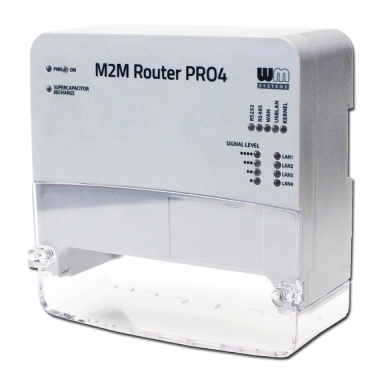
WM Systems M2M Router PRO 4 User manual

M2M Router PRO 4®
Installation Guide
v1.4
_________________________________________
2019-07-19

Document specifications
This document was made for the M2M Router PRO 4®
router
device
and it contains all relevant
installation steps of the device.
Document category:
Installation Guide
Document subject:
M2M Router PRO 4
®
Author:
WM Systems LLC
Document version No.:
REV 1.40
Number of pages:
34
Linux Kernel:
4.14.23
OpenWRT software version:
201905271
Document status:
FINAL
Last modified:
19 July, 2019
Approval date:
19 July, 2019

Table of contents
1. WIRING AND PREPARATION........................................................................ 4
1.1 Description of interfaces ..................................................................................................... 4
1.2 Safety declaration .............................................................................................................. 5
1.3 Mounting, fixation .............................................................................................................. 9
1.4 Cabling, wiring................................................................................................................... 10
1.5 Important notes ................................................................................................................. 14
1.6 Understanding the LED signals............................................................................................ 14
2. INSTALLING THE ROUTER............................................................................ 16
2.1 The very first startup.......................................................................................................... 16
2.2 Normal startup................................................................................................................... 17
2.3 Local access via Ethernet.................................................................................................... 19
2.4 Local access via USB LAN ................................................................................................... 19
2.5 Web user interface and Login ............................................................................................. 20
2.6 SSH access ........................................................................................................................ 22
2.7 Wireless access.................................................................................................................. 23
2.8 LED indication.................................................................................................................... 25
2.9 Power On / Supercap Charging mode .................................................................................. 26
2.10 Service features ............................................................................................................... 28
3. ROUTER CONFIGURATION (MAIN IMPORTANT SETTINGS) ........................... 31
4. SUPPORT..................................................................................................... 33
5. LEGAL NOTICE ............................................................................................ 34

1. Wiring and Preparation
1.1 Description of interfaces
0 –Optional (not presented by general) ~110 - 230V AC connector can be supplied (4-pins
terminal block, order option), pinout from left-to-right: L, N, -, PE
1 –Power supply connector (12..24V DC, 2-pin terminal block), pinout from left-to-right: -/+
2 –micro SD card slot (for uSD card, for alternative uSD boot or data storage)
3 –micro USB connector (PC connection - USB LAN bridge - for configuration, debug)
4 –Primary SIM-card slot (2FF-type mini SIM card, push-insert)
5 –Secondary SIM-card slot for DUAL SIM option feature (2FF-type mini SIM card, push-
insert) –currently the DUAL SIM feature is not supported (under development)
6 –Ethernet LAN1 port (IEE 802.3, 100/10 Mbit FastEthernet, full duplex, bridged, RJ45
connector)
7 –Ethernet LAN2 port (IEE 802.3, 100/10 Mbit FastEthernet, full duplex, bridged, RJ45
connector)
8 –Ethernet LAN3 port (IEE 802.3, 100/10 Mbit FastEthernet, full duplex, bridged, RJ45
connector)
9 –Ethernet LAN4 port (IEE 802.3, 100/10 Mbit FastEthernet, full duplex, bridged, RJ45
connector)
2
13
3
4
8
9
10
12
11
~230VAC
L N - PE
1
0
6
7
5

10 –RS232/RS485 port (isolated RS232 and isolated RS485, half-duplex data interface,
RJ12 connector)
11 –Reset button (hole) –has multiple features, see
Reset
features
chapter later
12 –ANT Main –Primary antenna connector for 4G LTE, SMA-M, 50 Ohm (obligatory to use)
13 –ANT Diversity - Diversity antenna connector 4G LTE, SMA-M, 50 Ohm (recommended
to use for 4G LTE)
1.2 Safety declaration
The device must be used and operated according to the related user manual.
The installation can be carrying out only by a responsible, instructed and skilled
person by the service team, who has enough experience and knowledge about
carrying oug the wiring and installing a router device.
Its prohibited to touch or modify the wiring or the installation by the user. It is probibited to
open the device enclosure during its operation or under power connection.
It is also prohibited to remove or modify the device PCB. The router and it’s parts must not be
changed by other items or devices.
Any modification and repairation is not allowed without the permission of the manufacturer. It
all causes the loss of product warranty.
Only a certified expert or the manufacturer is allowed to open the enclosure!
Caution!
By general the device is using DC mains. 24V DC mains electric shock (12..24V DC)
hazard inside the enclosure! DO NOT open the enclosure and DO NOT touch the PCB.
In case of using the optional orderable AC power source, please consider the
following. ~110-230V AC 50Hz, electric shock (~110-230V AC) hazard
inside the enclosure! DO NOT open the enclosure and DO NOT touch the PCB.
(Consumption: Min. 3W / Average (2G/3G communication): 4W / Advanced (4G LTE
communication): 10W / Max: 15W (with expansion and 2nd wireless module)
The IP51 immunity protection will be effective only in case of under normal usage
and operation conditions with unharmed hardware conditions by using the device in
the provided enclosure/chassis.

Deliberate damage or occing casualty of the device means the loss of product
warranty.
To ensure general safety, please follow the following guideline!
■Keep the chassis area clear and dust-free during and after installation.
■Keep tools and chassis components away from walk areas.
■Do not wear loose clothing that could get caught in the chassis. Fasten your tie or scarf and
roll up your sleeves.
■Wear safety glasses when working under conditions that might be hazardous to your eyes.
■Do not perform any action that creates a hazard to people or makes the equipment unsafe.
Safety with Electricity
Follow this guideline when working on equipment powered by electricity.
■Read all the warnings in Safety Warnings.
■Locate the emergency power-off switch for your installation location. If an electrical accident
occurs, you can quickly turn off the power.
■Disconnect all power before:
–Installing or removing a chassis
–Working near power supplies
■Look carefully for possible hazards in your work area, such as moist floors, ungrounded
power extension cables, frayed power cords, and missing safety grounds.
■Do not work alone if hazardous conditions exist.
■Never assume that power is disconnected from a circuit. Always check.
■Never open the enclosure of the router’s internal power supply.
■If an electrical accident occurs, proceed as follows:
–Use caution; do not become a victim yourself.

–Turn off power to the device.
–If possible, send another person to get medical aid. Otherwise, assess the victim’s
condition and then call for help.
–Determine if the person needs rescue breathing or external cardiac compressions; then
take appropriate action.
Preventing Electrostatic Discharge Damage
Electrostatic discharge (ESD) can damage equipment and impair electrical circuitry. It may
occur if electronic printed circuit cards are improperly handled and may cause complete or
intermittent failures. Always follow ESD prevention procedures when removing and replacing
modules:
■Ensure that the router chassis is electrically connected to earth ground.
■Wear an ESD-preventive wrist strap, ensuring that it makes good skin contact. Connect the
clip to an unpainted surface of the chassis frame to channel unwanted ESD voltages safely to
ground. To guard against ESD damage and shocks, the wrist strap and cord must operate
effectively.
■If no wrist strap is available, ground yourself by touching a metal part of the chassis.
Caution: For the safety of your equipment, periodically check the resistance value of the
antistatic strap. It should be between 1 and 10 megohms (Mohm).
Warning!
IMPORTANT SAFETY INSTRUCTIONS
This warning symbol means danger. You are in a situation that could cause bodily injury.
Before you work on any equipment, be aware of the hazards involved with electrical circuitry
and be familiar with standard practices for preventing accidents. Use the statement number
provided at the end of each warning to locate its translation in the translated safety warnings
that accompanied this device.
SAVE THESE INSTRUCTIONS
Warning: Before working on equipment that is connected to power lines, remove jewelry
(including rings, necklaces, and watches). Metal objects will heat up when connected to power
and ground and can cause serious burns or weld the metal object to the terminals. Statement
43

Warning: In order to comply with FCC radio frequency (RF) exposure limits, antennas should
be located at a minimum of 7.9 inches (20 cm) or more from the body of all persons.
Statement 332
Warning: Do not work on the system or connect or disconnect cables during periods of
lightning activity. Statement 1001
Warning: Before performing any of the following procedures, ensure that power is removed
from the DC circuit. Statement 1003
Warning: Read the installation instructions before you connect the system to its power source.
Statement 1004
Warning: This product relies on the building’s installation for short-circuit (overcurrent)
protection. Ensure that the protective device is rated not greater than: 20A. Statement 1005
Warning: This unit is intended for installation in restricted access areas. A restricted access
area can be accessed only through the use of a special tool, lock and key, or other means of
security. Statement 1017
Warning: The plug-socket combination must be accessible at all times, because it serves as the
main disconnecting device. Statement 1019
Warning: This equipment must be grounded. Never defeat the ground conductor or operate
the equipment in the absence of a suitably installed ground conductor. Contact the appropriate
electrical inspection authority or an electrician if you are uncertain that suitable grounding is
available. Statement 1024
Warning: This unit might have more than one power supply connection. All connections must
be removed to de-energize the unit. Statement 1028
Warning: Only trained and qualified personnel should be allowed to install, replace, or service
this equipment. Statement 1030
Warning: Ultimate disposal of this product should be handled according to all national laws and
regulations. Statement 1040
Warning: For connections outside the building where the equipment is installed, the following
ports must be connected through an approved network termination unit with integral circuit
protection:
10/100 Ethernet. Statement 1044
Warning: To prevent the system from overheating, do not operate it in an area that exceeds
the maximum recommended ambient temperature of: Statement 1047
Warning: Installation of the equipment must comply with local and national electrical codes.
Warning: To prevent airflow restriction, allow clearance around the ventilation openings to be
at least: 3 inches (7.6 cm). Statement 1076
Warning: Hot surface. Statement 1079
Caution: This industrial router can only be accessed by service personnel or by users who have
been instructed about the reasons for the restrictions applied to the location. Access is through
the use of a tool or lock and key, or other means of security, and is controlled by the authority
responsible for the location.
Caution: Be aware of the size and weight of the industrial Router when mounting. Ensure that
the mounting location has a stable flat surface and can safely support the weight of the device.
1.3 Mounting, fixation
The device enclosure (unit) contains a DIN-Rail fixation due its case, which is to be intended to
mount to DIN-35 rail or using a 3-point fixation by screws, or using the hook (in hanging
position).
You can also mount the enclosure to wall, place into server rack or similar fixation opportunity.
The unit must be mounted inside a cabinet by the listed fixation points, in vertical orientation.
Please note that close metal parts, the cabinet metal material and the industrial conditions as
the usage of high rate power or other external gained radio frequency signals can cause radio
signal disturbance and could cause weak wireless signal at reception or data transmitting or
could cause less effective signal reception, weak wireless fidelity. In any of these, we recommend
you to test the wireless signal reception and quality and if it is necessary use external, magnetic
mount antenna which is leaded outside of the cabinet and placed onto the cabinet’s surface –
to ensure enough reception.
Figure of bottom side of the unit enclosure
A –Device housing case back plate
B –Hook for fixation to wall/mount
C –DIN-rail sleede for fixation
D –DIN-rail position holder (release/fixate)
E –Additional hooks for fixation to wall/mount

1.4 Cabling, wiring
1. Remove the plastic, transparent port protector (No. 15) part by releasing the two
screws (No. 14) from the top of the enclosure and slide up the plastic part, then remove
upside.
Now you can free to connect
wires and cables to the ports
and interfaces.
2. Mount a 4G LTE antenna to
the ANT Main titled (no. 12)
SMA antenna connector and
mount an recommended to also
using a secondary antenna also
and mount to the ANT
Diversity (no. 13) SMA
connector. Twist the antenna to
the connector until it is
fastened.
B
A
C
D
E
E
14
14
15

You can use 4G LTE wireless antenna with 3-6dB, 9dB or more gained versions. RG174 cable
SMA antenna with magnetic mount can be also using for external usage.
The antenna must be placed and oriented that it should has a some clearance in any
direction.
3. Insert and push an activated mini SIM card to the SIM 1 titled card holder (No. 4), top
SIM holder. Insert by following the hints of SIM card figure for the proper orientation. (The
SIM chip-side will be face down and the cutted edge towards to inside and push until it
sleeves).
4. If you are using the DUAL SIM feature you need to insert the secondary SIM card into the
bottom SIM holder - SIM 2 titled (No. 5). The secondary SIM card must be oriented like this:
the SIM chip face up and the SIM title down.
5. You can use the microUSB (No. 3) connector with a
microUSB-to-USB
cable connection as
USB LAN - instead of the Ethernet connection.
6. Beside / instead of USB connection you can connect an UTP cable to the LAN1 (No. 6)
and/or LAN2 (No. 7), LAN3 (No. 8), LAN4 (No. 9) RJ45 interface Ethernet port.
The other side of the UTP cable must be plugged to your computer or a network device
(hub or switch, if you are attempted to use one).
Note, that the Ethernet ports are bridged by default, which means its equal which port you
are using.
2
13
3
4
8
9
10
12
11
1
6
7
5

7. By default, the router has an installed OpenWRT®operating system which is ready to use
and configure to your SIM card APN and for you usage requirements.
8. Plug the 24V DC power supply to the 12..24V DC interface (No. 1), then plug the
adapter to the external 24V DC (12..24V DC) power supply –according the pinout (from
left-to right direction: - / +), to the terminal block part of the power supply and connect to
the device, by adding stable 24V DC power.
Current and power consumption (DC power source / mains)
Power supply / Voltage range: 12..24 VDC
Current: 800mA at 24V DC
Consumption: 2.5 - 10W
The following cables are not part of the accessories of the delivered package
Use the following hints and the recommendation to choose useful cable and type to prepare
the necessary connection(s) according to your requirements.
DC cable:
The power cord 70 cm type, OMYA 2 x 1 mm^2, voltage Insulation min. 24 V, maintaining
colors and ends with the power supply enabling connection to a 24 V DC
Function: 12-24V DC power supply to the router
Pins must be wired for usage: L (+), N (-) (see schematic for pinout)
AC cable (optional):
The power cord 70 cm type, OMYA 2 x 1 mm^2, voltage Insulation min. 500 V, maintaining
colors and ends with the power supply enabling connection to a 230 V AC
Function: ~110-230V AC power supply to the router
Pins must be wired for usage: L, N (see schematic for pinout)
UTP (Ethernet) cable:
Cable Type: Cat5e UTP PVC
In case of presence of ~110-230V AC interface, you can use ~110-230V AC power input
source (No. 0 interface) to connect AC supply power for the device.
Current / power consumption (AC power source) –optional mains input
Power supply / Voltage range: ~110-230V AC, 50 Hz
Current: 0.1A at ~230V AC Consumption: 2.5 - 10W

Connector type: RJ45 Ethernet
Function: RJ45 (LAN) Ethernet connector to external device
RS232/RS485 cable:
Type: 2 + 3x LgY 0.75 mm2
Connector type: RJ12
Function: RS232 connector to external device / R485 connector to external device
microUSB-USB configuration cable:
Type: micro-USB-USB cable
Connector típe: USB 2.0 micro Type B connector
Function: alternative LAN bridge (USB LAN) for configuration –connecting to computer
Schematic figure of wiring, interfaces, pinout –DC power outfit
Schematic: wiring of the AC / DC power source

1.5 Important notes
The DUAL SIM mode is currently inactive (feature is under development).
You have to use two 4G LTE antenna for the stable wireless network operation. You can
check the signal reception and wireless availability in the Overview menu.
The available APN settings will be assured by the SIM card provider mobile operator or your
mobile internet service provider. Ask them about APN, password, SIM PIN and further
necessary information for the configuration.
When configuring the SIM or APN settings, after the saving the router, it will not restart the
modem automatically with the new settings. You need to restart the modem by the Restart
WAN button in the OpenWrt®menu at Network / Modem settings.
1.6 Understanding the LED signals
The router has 16 LEDs to assign the router current status, the communication, connection.
These LEDs are located in four groups:
-Operation status LEDs (Group A)
oPWR –Power source connected / mains on
oON –The router has started
oSUPERCAPACITOR CHARGE (in case of exhausted supercapacitor it shows the
recharge)
-Connectivity LEDs (Group B)
oRS232 connection and activity (on the RJ12 connector)
oRS485 connection and activity (on the RJ12 connector)
oWAN –wireless network connection and access
oUSBLAN connection (on microUSB port)
oKERNEL –for sign possible failures, stand-by mode
-cellular network signal strength indication LEDs (Group C)
osignal 1 to signal 4: wireless signal reception (higher is better)
-LAN (Ethernet) connectivity LEDs (Group D)
oLAN1 port to LAN4 (by the detected the RJ45 port connection)

The power indication group (group A) and signal level leds (group C) are is fixed, but the other 9
LEDs (group B and group D) are free to reonfigurable.
D
C
A
B

2. Installing the router
2.1 The very first startup
The router has a supercapacitor inside which can protect the device against short (<5sec) power
outages. Therefore this part can be charged and it can be exhausted after an outage or if you store
the router for months without connecting power source or using.
In these cases you cannot start the router as usual by adding the DC power supply only, because
only the PWR led will be active (lighing by green), but the router won’t start further.
First, you must start the router by the adding the power source and pushing the Reset button
(No. 11) for 2 seconds by a sharp object (e.g. by a pen) –while the ON led will be also active (all
the two leds are lighting by green colour) –then you can release the Reset button.
Then the router will start immediately and charging the supercapacitor (SUPERCAPACITOR
CHARGE led will be also active –by yellow colour).
Next time you don’t need to push the Reset. You can stop it by removing the power source and
start it by adding the DC power.

2.2 Normal startup
The router has a pre-installed system (which contains the router firmware and the pre-configured
OpenWrt®system).
After adding power source to the router you will just need to configure some necessary and unique
settings for your SIM card, network access, and some other required connection parameters.
Please, start the router by the following sequence.
1. Ensure that you have inserted an activated SIM card into SIM 1 holder (No. 4) in the right
position. The usage of SIM 1 holder is obligatory to use for wireless communication.
2. Only if you are using DUAL SIM version, insert active SIM card into SIM 2 titled holder also.
3. Ensure that antennas are mounted to the SMA interfaces (No. 12 and 13).
4. After plugging the DC Power source (No. 1), the router begins to perform booting –the
LED signals are always showing the current activity during the operation.
The system start needs about 40-50 seconds while it will be ready for usage, network
communication.
5. During the boot, the router begins to operate, whereas its LED signals are showing the
current activity during the operation.
Boot sequence:
a.) First the LAN1 –LAN4 leds are blinking for half a second, which signs that the power was
added. The PWR and ON leds are also active (lighing by green).
b.) Then the RS232 and RS485 LEDs are ligthing for ~10 seconds during the firmware start.

c.) The RS232, RS485, WAN, USBLAN leds will be flashing during 30 seconds until boot.
d.) At the end of the boot process, only the WAN, USBLAN leds are flashing for 5-10 seconds.
e.) When the connectivity LEDs are not blinking anymore the load of the system has finished.
f.) If the WAN (APN) was not configured, the SIGNAL LEVEL low LED is blinking which means
the router tries to connect to the wireless network. If it will was configured properly (APN,
password and SIM PIN is matching) and the registration was succesful, then the WAN led

will be lighting and the current SIGNAL LEVEL leds will be also lighting its signal strength
value which means connected and you have useful wireless signal reception for the usage
and data transmitting.
g.) If you have already connected the USBLAN or LAN1..LAN4 or the RS232/RS485, the
interface connectivity led will be also active and signing the network connection and data
traffic.
When the router has reached the listed point „e.)” then the device is already accessible on its LAN
and USBLAN interfaces, therefore now you can login to the LuCi®web user interface (or connect
via SSH).
2.3 Local access via Ethernet port (LAN1..LAN4 interfaces)
The router’s default Ethernet IP address is 192.168.1.1
Add the 192.168.1.x IPv4 address (where x can be between 2 and 255) to your computer’s
Ethernet interface for connecting to the router.
Then you can access the device through the web user interface or by SSH.
For connecting to the router on web interface use the https://192.168.1.1 URL.
Important!
The DHCP service is turned on for the Ethernet interfaces, by default.
The ETH1..ETH4 interfaces are bridged, therefore its not important which port are you currently
using, all network data and TCP/IP packets will be relied.

2.4 Local access via USB LAN (USB connection)
1. Download, unpack and install the USBLAN driver for using the USB connection:
http://www.wmsystems.hu/m2m-downloads/USB_Ethernet_RNDIS_DRIVER.zip
2. After you’ve connected the USB-microUSB cable, you can add the driver in the Windows®/
Start / Control Panel / System / Device Manager. Find the Network Cards, extend
it and you will found the „USB Ethernet / RNDIS Gadget”. Double click on the entry and
choose the Driver tab, and the Refresh button, then browse the uncompressed file’s
directory then Install the driver.)
3. Build a connection between the PC and the router with a microUSB-to-USB cable.
4. Configure the USB-Ethernet interface IP address on your PC for the „USB
Ethernet/RNDIS Gadget” and setup the next fixed ipv4 address: 192.168.10.10, subnet
mask is: 255.255.255.0 –connect these settings.
(You can ping the device through the USB connection on its IP address.)
5. The USBLAN interface IP address is 192.168.10.1
For connecting to the router on web interface use the https://192.168.10.1 URL.
2.5 Web user interface and Login
1. The router’s local web user interface (LuCi®) is reachable through the Ethernet or
USB interface –on the default addresses.
2. Enter the router default web user interface (LuCi®) URL.
The Ethernet web interface default URL is: https://192.168.1.1
The USB web interface default URL is: https://192.168.10.1
3. Use the Mozilla®browser! In your browser window you will get a security risk message.
Ignore the security message and choose the Advanced option here.
Attention!
For accessing the web user interface we recommend to use the Mozilla Firefox®web browser.
Other browsers cannot be used.
Other manuals for M2M Router PRO 4
3
Table of contents
Other WM Systems Network Router manuals

WM Systems
WM Systems M2M PRO4 MODEM User manual

WM Systems
WM Systems M2M Router NB User manual

WM Systems
WM Systems M2M Router PRO 4 User manual

WM Systems
WM Systems M2M Industrial Router 2 SECURE User manual

WM Systems
WM Systems M2M PRO4 MODEM User manual

WM Systems
WM Systems M2M Router PRO 4 User manual

WM Systems
WM Systems M2M Industrial Router User manual

WM Systems
WM Systems M2M PRO4 DCU User manual

WM Systems
WM Systems M2M Router PRO 4 User manual

WM Systems
WM Systems M2M Router PRO4 User manual