Wolf DF304LP User manual

DUAL FUEL RANGE
INSTALLATION GUIDE
SPECIFICATIONS, INSTALLATION, AND MORE

DUAL FUEL RANGE
Contents
3Safety Precautions
4Specications
7Installation
11 Troubleshooting
Features and specications are subject to change at any
time without notice. Visit wolfappliance.com/specs for the
most up-to-date information.
2
|
Wolf Customer Care 800.222.7820
Important Note
To ensure this product is installed and operated as safely
and efciently as possible, take note of the following types
of highlighted information throughout this guide:
IMPORTANT NOTE highlights information that is especially
important.
CAUTION indicates a situation where minor injury or product
damage may occur if instructions are not followed.
WARNING states a hazard that may cause serious injury or
death if precautions are not followed.
IMPORTANT NOTE: Throughout this guide, dimensions in
parentheses are millimeters unless otherwise specied.
IMPORTANT NOTE: Save these instructions for the local
electrical inspector.

wolfappliance.com
|
3
SAFETY PRECAUTIONS
Product Information
Important product information including the model and
serial number are listed on the product rating plate. The
rating plate is located on the bottom of the control panel,
at the far right, just above the oven door. Refer to the
illustration below.
If service is necessary, contact Wolf Factory Certied
Service with the model and serial number. For the name of
the nearest Wolf Factory Certied Service or for questions
regarding the installation, visit the contact & support section
of our website, wolfappliance.com or call Wolf customer
care at 800-222-7820.
Rating plate location
RATING PLATE
IMPORTANT INSTRUCTIONS
WARNING
A child or adult can tip this appliance and be
killed.
Verify the anti-tip device has been properly
installed and engaged. Ensure the anti-tip device
is re-engaged when this appliance is moved. Refer
to the illustrations below for how to verify correct
installation.
Do not operate this appliance without the anti-tip
device in place and engaged. Failure to do so
can result in death or serious burns to children or
adults.
To reduce the risk of burns, do not move this
appliance while hot.
•This appliance is equipped with casters on two
or more legs and must be installed on 1/8"(3) thick
commercial grade vinyl composition oor nishing
materials or equivalent.
•This appliance is not approved for downward air-
ow ventilation or air curtain equivalent.
ANTI-TIP
DEVICE
ANTI-TIP
DEVICE
ENGAGED
Anti-tip device location
Anti-tip device engaged

4
|
Wolf Customer Care 800.222.7820
Installation Requirements
IMPORTANT NOTE: When installing against a combustible
surface, a minimum 10" (254) riser is required for a 36" dual
fuel range with charbroiler or griddle and all 48" and 60"
models. Follow all minimum clearances to combustible
surfaces shown in the illustration on page 6.
SPECIFICATIONS
Electrical
Installation must comply with all applicable electrical codes.
Locate the electrical supply ush with the wall or oor
and within the shaded area shown in the illustration on
page 6. A separate circuit servicing only this appliance is
required.
If a power supply cord is being used, the cord must be
designated for use with ranges and rated for 240 V, 30 or
50 amps (refer to the chart below), and must include 3 or 4
conductors. A 4-conductor cord is required for installations
where grounding through the neutral is prohibited.
Performance may be compromised if the electrical supply is
less than 240 volts.
ELECTRICAL REQUIREMENTS—SINGLE OVEN
Electrical Supply grounded, 240/208 VAC, 60 Hz
Service 30 amp dedicated circuit
Total Amps 21
Max Connected Load 5.2 kW
Min Supply Wire L1, L2, ground—12 AWG
neutral—16 AWG
ELECTRICAL REQUIREMENTS—DOUBLE OVEN
Electrical Supply grounded, 240/208 VAC, 60 Hz
Service 50 amp dedicated circuit
Total Amps 42.5
Max Connected Load 10.2 kW
Min Supply Wire L1, L2—8 AWG, ground—10 AWG
neutral—12 AWG

wolfappliance.com
|
5
Gas Supply
Installation must comply with local codes or, in the absence
of local codes, with the National Fuel Gas Code.
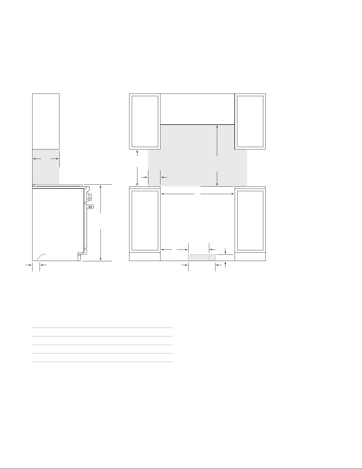
Locate the gas supply within the shaded area shown in the
illustration on the following page.
The range is equipped for use with natural or liquid propane
(LP) gas. It is design certied by the Canadian Standards
Association (CSA) for natural or LP gases. The product
rating plate has information on the type of gas that should
be used. For rating plate location, refer to the illustration
below. If this information does not agree with the type of gas
available, check with the local gas supplier The gas pres-
sure regulator is built into the unit.
GAS REQUIREMENTS
NATURAL GAS WC
Supply Pressure 5" (12.5 mb)
Min Line Pressure 7" (17.5 mb)
Max Regulator Pressure 14" (34.9 mb), .5 psi (3.5 kPa)
LP GAS WC
Supply Pressure 10" (25 mb)
Min Line Pressure 11" (27.4 mb)
Max Regulator Pressure 14" (34.9 mb), .5 psi (3.5 kPa)
SPECIFICATIONS
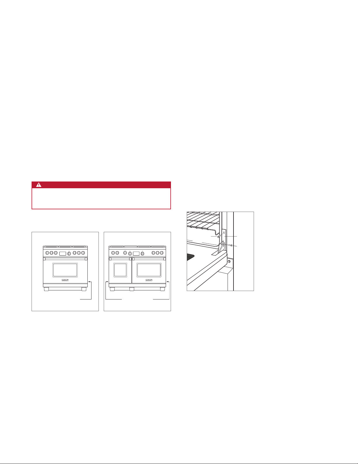
The range must be connected to a regulated gas supply.
The supply line must be equipped with an approved external
gas shut-off valve located near the range in an accessible
location. Do not block access to the shut-off valve. Refer to
the illustration below.
A gas supply of 3/4"(19) ID line must be provided to the
range. If local codes permit, a certied, 3' (.9 m) long, 1/2"(13)
or 3/4"(19) ID exible metal appliance connector is recom-
mended to connect the units 1/2" NPT female inlet to the
gas supply line. Pipe joint compounds, suitable for use with
natural or LP gas should be used.
The appliance and its shut-off valve must be disconnected
from the gas supply piping system during any pressure
testing of the system at test pressures in excess of .5 psi
(3.5 kPa). The appliance must be isolated from the gas
supply piping system by closing its individual manual shut-
off valve during any pressure testing of the system at test
pressures equal to or less than .5 psi (3.5 kPa).
Wolf natural gas ranges will function up to 10,250' (3124 m)
in altitude without adjustment and LP gas ranges will func-
tion up to 8,600' (2621 m). If the installation exceeds these
elevations, contact an authorized Wolf dealer for a high
altitude conversion kit.
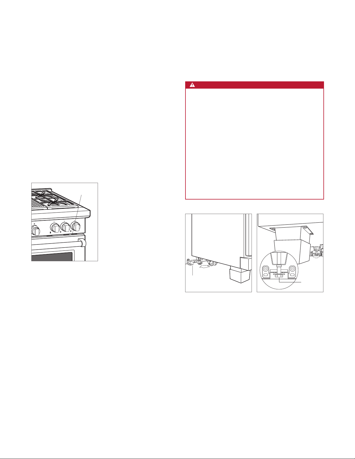
SHUT-OFF VALVE
OPEN POSITION
GAS SUPPLYTO APPLIANCE
Gas shut-off valve
Rating plate location
RATING PLATE

6
|
Wolf Customer Care 800.222.7820
SPECIFICATIONS
Dual Fuel Range
INSTALLATION
FRONT VIEWSIDE VIEW
*Without ventilation hood, 36"(914) minimum clearance countertop to combustible materials, 44"(118) for charbroiler.
NOTE: Shaded area above countertop indicates minimum clearance to combustible surfaces,
combustible materials cannot be located within this area.
For island installation, 12"(305) minimum clearance back of range to combustible rear wall above countertop.
13"
(330)
18"
(457)
6"
(152)
21/4"
(57)
LOCATION OF GAS AND
ELECTRICAL EXTENDS
ON FLOOR
A
31/4" (83)
10" (254)
GAS
13" (330)
ELECTRICAL
367/8" (937)
TO COOKING
SURFACE
W
OPENING WIDTH
30" (762) TO 36" (914)
TO BOTTOM OF
VENTILATION HOOD*
G E
OPENING WIDTH W A
30" Model 30" (762) 81/2"(216)
36" Model 36" (914) 131/2"(343)
48" Model 48" (1219) 24" (610)
60" Model 601/4"(1530) 31" (787)

wolfappliance.com
|
7
Preparation
Before moving the range, protect any nished ooring and
secure oven door(s) closed to prevent damage.
To lighten the load or to t through a door way, the oven
door(s) can be removed. Only remove if necessary. Do not
remove the griddle or any other component. Door removal
should only be done by a certied installer or service
technician.
For removal, a hinge pin will be inserted into the appropriate
hinge shown in the illustrations below. The pin(s) are located
inside the oven door. For single oven ranges, the hinge pin
must be inserted in the right hinge. For double oven ranges,
the pins must be placed in the outer two hinges.
CAUTION
Failure to insert the hinge pin in the appropriate hinge
arm will cause damage to the range.
INSTALLATION
OVEN DOOR REMOVAL
1Insert the hinge pin into the appropriate hinge.
2Remove the lower kickplate assembly to access the
lower hinge retainer mounting screws.
3Open the oven door and remove both upper and lower
hinge retainer mounting screws. The oven gasket may
have to be moved slightly to access the bottom screws.
4Move the hinge retainer plate forward slightly. The hinge
retainer plate will remain on the door hinge after the
mounting screws have been removed.
5Carefully close the oven door to approximately 60°, then
lift the door up and out. A slight rocking motion may be
required for removal.
SPRING HINGES
SPRING HINGE
SPRING HINGES
SPRING HINGE
Single oven ranges
Double oven ranges
KICKPLATE
UPPER
MOUNTING
SCREW
HINGE
RETAINER
PLATE
HINGE
PIN
Oven door removal

8
|
Wolf Customer Care 800.222.7820
INSTALLATION
Placement
Do not lift or carry the oven door by the door handle. The
range has rear casters which allow for easy movement by
lifting the front of the unit.
Use an appliance dolly to move the range near the opening.
Remove and recycle packing materials. Do not discard the
anti-tip bracket supplied with the range.
If a riser has been specied, refer to the installation instruc-
tions packaged with the riser. The riser must be installed
before the range is installed.
Leveling
Raise the range to its desired height by adjusting the front
legs and rear casters. Use a 3/4" socket to adjust the rear
casters. The front legs can be adjusted by rotating the
hexagonal leg clockwise to raise and counterclockwise to
lower.

wolfappliance.com
|
9
Anti-Tip Bracket
To prevent the range from tipping forward, the anti-tip
bracket must be installed. To ensure the anti-tip bolt
engages the bracket, refer to the chart and illustration below
to determine proper placement.
ANTI-TIP BRACKET A
30" Range 3/16"(5)
36" Range 9/16"(14)
48" Range 3/16"(5)
60" Range 5/16"(8)
INSTALL BRACKET
Drywall application: After properly positioning the anti-tip
bracket, mark holes, then use a Phillips screwdriver or a low
rpm power drill to drive the wall anchor into the surface of
the wallboard until ush. Pre-drill holes if needed. For hard
wallboard or double-board construction, use a 1/4" drill bit.
For solid plaster, use a 7/16" drill bit. Refer to the illustration
below. Use #8 screws and at washers to fasten the bracket
to the wall.
Wood oor application: After properly positioning the anti-
tip bracket, drill 3/16"(5) pilot holes through the oor. Use
#12 screws and at washers to secure the bracket to the
oor.
Concrete oor application: After properly positioning the
anti-tip bracket drill 3/8"(10) holes into the concrete a min-
imum of 11/2"(38) deep. Use 3/8" wedge anchors to secure
the bracket to the oor.
ANTI-TIP BOLT ADJUSTMENT
Once the bracket is secure, adjust the anti-tip bolt so the
top of the washer is 7/8"(22) maximum from the oor. Slide
the range into the opening and verify the anti-tip bolt is
engaged. Refer to the illustrations below.
A
ANTI-TIP
BRACKET
ANTI-TIP
BRACKET
WALL
ANCHOR
Anti-tip bracket location
Wall anchor installation
INSTALLATION
7/8" (22) MAX
ANTI-TIP
BOLT
ANTI-TIP
DEVICE
ENGAGED
Anti-tip bolt adjustment
Anti-tip bolt engaged

10
|
Wolf Customer Care 800.222.7820
Electrical Connection
The terminal block on the back of the range allows for a
3-wire or 4-wire installation. For a 4-wire installation, the
ground strap from the unit to the terminal block must be cut.
Two concentric knockouts are provided to allow for perma-
nent or cordset wiring of the unit.
THREE-WIRE ELECTRICAL SYSTEM
1Where local codes permit, connect the ground appliance
wire to the neutral (white) supply wire.
2Connect the ground and white appliance wires to the
neutral (white) supply wire in the electrical box.
3Connect the black appliance wire to the black (L1) power
supply wire in the electrical box.
4Connect the red appliance wire to the red (L2) power
supply wire in the electrical box.
FOUR-WIRE ELECTRICAL SYSTEM
1Separate the ground and white appliance wires.
2Connect the white appliance wire to the neutral (white)
supply wire in the electrical box.
3Connect the black appliance wire to the black (L1) power
supply wire in the electrical box.
4Connect the red appliance wire to the red (L2) power
supply wire in the electrical box.
5Connect the ground appliance wire to the green/ground
house grounding wire in the electrical box.
INSTALLATION
Gas Supply Connection
All connections to the gas piping must be wrench-tightened.
Do not overtighten or allow pipes to turn when tightening.
If a exible metal connector is being used, verify it is not
kinked, then attach the gas supply line to the regulator on
the range. Open the valve and check for leaks by placing a
liquid detergent solution onto all gas connections. Bubbles
around connections indicate a gas leak. If a leak appears,
close the shut-off valve and adjust connections.

Troubleshooting
IMPORTANT NOTE: If the range does not operate properly,
follow these troubleshooting steps:
•Verify electrical power is supplied to the range.
•Verify the gas supply shut-off valve is in the open
position.
•If the range does not operate properly, contact Wolf
Factory Certied Service. Do not attempt to repair the
range. Wolf is not responsible for service required to
correct a faulty installation.
TROUBLESHOOTING
wolfappliance.com
|
11
Sub-Zero, Sub-Zero & Design, Sub-Zero & Snowake Design, Dual Refrigeration, The Living Kitchen, Great American Kitchens The Fine Art of Kitchen Design, Wolf, Wolf &
Design, Wolf Gourmet, W & Design, red colored knobs, Cove, and Cove & Design are registered trademarks and service marks of Sub-Zero Group, Inc. and its subsidiaries.
All other trademarks are property of their respective owners in the United States and other countries.

2
|
Atención al cliente de Wolf 800.222.7820
ESTUFAS DE ENERGÍA DUAL
Contenido
3Precauciones de seguridad
4Especicaciones
7Instalación
11 Resolución de problemas
Las características y especicaciones están sujetas a
cambios sin previo aviso. Visite wolfappliance.com/specs
para obtener la información más actualizada.
Aviso importante
Para garantizar que este producto se instale y opere de
la forma más segura y eciente posible, tome nota de los
siguientes tipos de información resaltada en esta guía:
AVISO IMPORTANTE señala la información que es
especialmente importante.
PRECAUCIÓN indica una situación en la que se pueden
sufrir heridas leves o provocar daños al producto si no se
siguen las instrucciones.
ADVERTENCIA indica peligro de que se produzcan heridas
graves o incluso la muerte si no se siguen las precauciones.
AVISO IMPORTANTE: en toda esta guía, las dimensiones
entre paréntesis son milímetros, a menos que se especique
lo contrario.
AVISO IMPORTANTE: guarde estas instrucciones para el
inspector eléctrico local.

wolfappliance.com
|
3
PRECAUCIONES DE SEGURIDAD
Información del producto
La información importante del producto, incluido el modelo
y número de serie de la unidad, se encuentra en la placa de
datos del producto. La placa de datos se encuentra en la
parte inferior del montaje del panel de control, en el extremo
derecho, justo por encima de la puerta del horno. Consulte
la siguiente ilustración.
Si necesita servicio, póngase en contacto con el centro de
servicio autorizado de Wolf y tenga a la mano el modelo y
número de serie de la unidad. Para obtener los datos del
centro de servicio autorizado de Wolf más cercano o si
tiene preguntas acerca de la instalación, visite la sección de
contacto y soporte técnico en nuestra página de Internet
wolfappliance.com o llame a la línea de atención al cliente
de Wolf al 800-222-7820.
Ubicación de la placa de datos
PLACA DE DATOS
INSTRUCCIONES IMPORTANTES
ADVERTENCIA
Si un niño o un adulto jalan el electrodoméstico
este puede volcarse y causarles la muerte.
Compruebe que el dispositivo antivuelco haya
sido instalado y esté enganchado correctamente.
Asegúrese de volver a enganchar el dispositivo
antivuelco después de cambiar el electrodoméstico
de lugar. Consulte las ilustraciones siguientes para
saber cómo comprobar su instalación correcta.
No opere este electrodoméstico sin el dispositivo
antivuelco en posición y enganchado. No seguir
esta instrucción puede resultar en la muerte o en
graves quemaduras en niños o adultos.
Para reducir el riesgo de quemaduras, no mueva
el electrodoméstico mientras está caliente.
•Este electrodoméstico está equipado con ruedas en
dos o más patas y debe ser instalado sobre pisos
de grado comercial con 1/8"(3) de grosor, hechos de
materiales compuestos con vinilo o equivalentes.
•Este electrodoméstico no ha sido aprobado para la
ventilación con ujo aire dirigido hacia abajo o una
cortina de aire equivalente.
DISPOSITIVO
ANTIVUELCO
DISPOSITIVO
ANTIVUELCO
ENGANCHADO
Ubicación del dispositivo
antivuelco
Dispositivo antivuelco
enganchado

4
|
Atención al cliente de Wolf 800.222.7820
Requisitos de instalación
AVISO IMPORTANTE: al realizar la instalación contra una
supercie combustible, se requiere una tarima con altura
mínima de 10" (254) para una estufa de energía dual de 36"
(914) con parrilla o plancha y para todos los modelos de 48"
(1219) y 60" (1524).
ESPECIFICACIONES
Instalación eléctrica
La instalación debe tener una conexión a tierra de
conformidad con los códigos locales o, en ausencia de
códigos locales, con el Código Nacional de Electricidad,
ANSI/NFPA 70.
Coloque el suministro eléctrico a ras con la pared o el piso y
dentro del área sombreada que se muestra en la ilustración
de la página 6.
Si se utiliza un cable de alimentación, el cable debe haber
sido concebido para uso con estufas y tener capacidad
para 240 V, 30 o 50 amperes (consulte la tabla siguiente),
y debe incluir 3 o 4 conductores. Se requiere un cable de
4 conductores para instalaciones en las que está prohibido
realizar la conexión a tierra a través del cable neutro.
El rendimiento puede verse comprometido si el suministro
eléctrico es menor a 240 voltios.
REQUISITOS ELÉCTRICOS—HORNO SENCILLO
Suministro eléctrico Con conexión a tierra, 240/208 V
CA, 60 Hz
Servicio Circuito dedicado de 30 amperes
Total de amperes 21
Carga máxima conectada 5.2 kW
Cable de suministro mínimo L1, L2, a tierra—12 AWG
neutro—16 AWG
REQUISITOS ELÉCTRICOS—HORNO DOBLE
Suministro eléctrico Con conexión a tierra, 240/208 V
CA, 60 Hz
Servicio Circuito dedicado de 50 amperes
Total de amperes 42.5
Carga máxima conectada 10.2 kW
Cable de suministro mínimo L1, L2—8 AWG, a tierra—10 AWG
neutro—12 AWG

wolfappliance.com
|
5
Suministro de gas
La instalación debe cumplir con los códigos locales o,
en ausencia de códigos locales, con el Código Nacional
de Gas Combustible.
Localice el suministro de gas en la zona sombreada que se
muestra en la ilustración de la página 6.
La estufa está equipada para su uso con gas licuado
(LP) o propano natural. Su diseño está certicado por la
Asociación Canadiense de Normas (CSA, por sus siglas
en inglés) para gas natural o LP. La placa de datos del
producto contiene información sobre el tipo de gas que
se debe utilizar. Para ubicar la placa de datos, consulte
la siguiente ilustración. Si esta información no coincide
con el tipo de gas disponible, consulte con el proveedor
de gas local. El regulador de presión de gas se encuentra
interconstruido dentro de la unidad.
REQUISITOS DEL SUMINISTRO DE GAS
GAS NATURAL
Presión del suministro de gas 5" (12.5 mb) WC
Presión mínima de la línea 7" (17.5 mb) WC
Presión máxima hacia el
regulador
14" (34.9 mb) WC, .5 psi (3.5 kPa)
GAS LP
Presión del suministro de gas 10" (25 mb) WC
Presión mínima de la línea 11" (27.4 mb) WC
Presión máxima hacia el
regulador
14" (34.9 mb) WC, .5 psi (3.5 kPa)
ESPECIFICACIONES
La estufa debe conectarse a un suministro de gas regulado.
La línea del suministro debe estar equipada con una llave
de paso externa aprobada para gas ubicada cerca de la
estufa en un lugar accesible. No bloquee el acceso a la llave
de paso. Consulte la siguiente ilustración.
Se debe proporcionar una línea de suministro de gas de
3/4"(19) de línea de diámetro interno para la estufa. Si el
código local lo permite, se recomienda utilizar un conector
metálico exible certicado, de 3' (.9 m) de largo, 1/2"(13) o
3/4"(19) de diámetro interior para conectar la entrada NPT
hembra de 1/2" de la unidad a la línea de suministro de gas.
Debe utilizar compuestos para juntas de tubería aptos para
uso con gas natural o gas LP.
Debe desconectar el electrodoméstico y la llave de paso del
sistema de tuberías del suministro de gas durante cualquier
prueba de presión del sistema a presiones de prueba
mayores a 5 psi (3.5 kPa). Debe aislar el electrodoméstico
del sistema de tuberías del suministro de gas cerrando
manualmente la llave de paso durante cualquier prueba
de presión del sistema a presiones de prueba iguales o
inferiores a .5 psi (3.5 kPa).
Las estufas a gas natural de Wolf funcionarán hasta
10,250' (3124 m) de altitud sin ajuste y las estufas a gas LP
funcionarán hasta 8,600' (2621 m). Si la instalación supera
estas elevaciones, póngase en contacto con su distribuidor
autorizado de Wolf para conseguir un kit de conversión para
regiones altas.
LLAVE DE PASO EN
POSICIÓN ABIERTA
SUMINISTRO
DE GAS
A LA UNIDAD
Llave de paso del suministro
de gas
Ubicación de la placa de datos
PLACA DE DATOS

6
|
Atención al cliente de Wolf 800.222.7820
ESPECIFICACIONES
Estufa de energía dual
INSTALACIÓN
ESTUFA DE ENERGÍA DUAL W A
Estufa de 30" 30" (762) 81/2"(216)
Estufa de 36" 36" (914) 131/2"(343)
Estufa de 48" 48" (1219) 24" (610)
Estufa de 60" 601/4"(1530) 31" (787)
VISTA FRONTALVISTA LATERAL
*Sin campana extractora, distancia mínima de 36"(914) desde el mostrador hasta los materiales combustibles, 44"(118) para la parrilla.
NOTA : La zona sombreada sobre el mostrador indica la distancia mínima a las superficies combustibles, los materiales combustibles no se
pueden colocar en esta área.
Para instalaciones en isla, distancia mínima de 12" (305)de la parte posterior de la estufa a la pared trasera inflamable sobre el mostrador.
13"
(330)
18"
(457)
6"
(152)
21/4"
(57)
UBICACIÓN DE
LAS EXTENSIONES DE
GAS Y ELECTRICIDAD
EN EL PISO
A
31/4" (83)
10" (254)
GAS
13" (330)
ELECTRICIDAD
367/8" (937)
A LA
SUPERFICIE
PARA COCINAR
W
ANCHURA DE ABERTURA
30" (762) A36" (914)
A LA PARTE INFERIOR DE
LA CAMPANA DE VENTILACIÓN*
G E

wolfappliance.com
|
7
Preparación
Antes de mover la estufa, proteja cualquier suelo acabado y
asegúrese de que la puerta del horno esté cerrada para que
no se dañe.
Puede quitar la(s) puerta(s) del horno para aligerar la carga
o para pasar el horno por una puerta. Quítela únicamente
si es necesario. No retire la plancha ni ninguno de los otros
componentes. El proceso para quitar la puerta del horno
solamente debe ser realizado por un instalador certicado o
un técnico de servicio.
Para quitarla, se insertará un pasador de bisagra en la
bisagra correspondiente como se muestra en las siguientes
ilustraciones. El pasador (pasadores) se encuentra al interior
de la puerta del horno. Para las estufas con horno sencillo,
el pasador de la bisagra se debe insertar en la bisagra
derecha. Para las estufas con horno doble, los pasadores
se deben colocar en las dos bisagras exteriores.
PRECAUCIÓN
No insertar el pasador de la bisagra en el brazo de la
bisagra correspondiente provocará que la estufa se
dañe.
INSTALACIÓN
CÓMO QUITAR LA PUERTA DEL HORNO
1Inserte el pasador de la bisagra en la bisagra
correspondiente.
2Retire el montaje del zócalo inferior para acceder a los
tornillos de montaje del retenedor de la bisagra inferior.
3Abra la puerta del horno y retire los tornillos de montaje
del retenedor de la bisagra superior y de la inferior. Es
posible que deba mover ligeramente el empaque del
horno para ganar acceso a los tornillos de abajo.
4Mueva la placa de retención de la bisagra ligeramente
hacia adelante. La placa de retención de la bisagra
permanecerá en la bisagra de la puerta después de
haber quitado los tornillos de montaje.
5Cierre cuidadosamente la puerta del horno a
aproximadamente 60°, a continuación levante la puerta
hacia arriba y hacia afuera. Un suave movimiento de
balanceo puede ser necesario para extraerla.
ZÓCALO
TORNILLO DE
MONTAJE
SUPERIOR
PLACA DE
RETENCIÓN
DE LA
BISAGRA
PASADOR
DE LA
BISAGRA
Cómo quitar la puerta del horno
BISAGRAS DE RESORTE
BISAGRA DE RESORTE
BISAGRAS DE RESORTE
BISAGRA DE RESORTE
Estufas con horno sencillo
Estufas con horno doble

8
|
Atención al cliente de Wolf 800.222.7820
INSTALACIÓN
Colocación
No utilice la manija de la puerta del horno para levantar la
puerta ni para transportarla. La estufa tiene ruedas traseras
para facilitar su desplazamiento levantando el frente de la
unidad.
Utilice una plataforma rodante para mover la unidad cerca
de la abertura. Retire y recicle los materiales de embalaje.
No deseche el soporte antivuelco suministrado con la
estufa.
Si se ha especicado el uso de una tarima, consulte las
instrucciones de instalación que vienen con la tarima. Debe
instalar la tarima antes de instalar la estufa.
Nivelación
Para levantar la unidad a la altura deseada, ajuste las patas
delanteras y las ruedas traseras. Utilice una llave de 3/4"
para ajustar las ruedas traseras. Las patas delanteras se
pueden ajustar girando la pata hexagonal hacia la derecha
para subir y hacia la izquierda para bajar.

wolfappliance.com
|
9
Soporte antivuelco
Para evitar que la unidad se incline hacia delante y propor-
cionar una instalación estable, la unidad debe estar asegu-
rada en su lugar con el soporte antivuelco. Para asegurarse
de que el perno antivuelco se acople con el soporte,
consulte el gráco y la ilustración de abajo para determinar
cómo colocarlo correctamente.
SOPORTE ANTIVUELCO A
Estufa de 30" 3/16"(5)
Estufa de 36" 9/16"(14)
Estufa de 48" 3/16"(5)
Estufa de 60" 5/16"(8)
CÓMO INSTALAR EL SOPORTE
Aplicación en panel de yeso: Después de colocar
correctamente el soporte antivuelco, marque los oricios,
luego utilice un desarmador Phillips o un taladro eléctrico a
bajas rpm para introducir el anclaje de pared en el panel de
yeso hasta que quede a ras con la supercie. Si es necesario
taladre los oricios con anticipación. Para paneles de yeso
duro o construcción de doble placa, utilice una broca de
1/4". Para yeso sólido, utilice una broca de 7/16". Consulte la
siguiente ilustración. Utilice tornillos #8 y arandelas planas
para sujetar el soporte a la pared.
Aplicación en piso de madera: Después de colocar
correctamente el soporte antivuelco, taladre oricios guía
de 3/16"(5) en el piso. Utilice tornillos #12 y arandelas planas
para asegurar el soporte al piso.
Aplicación en piso de concreto: Después de colocar
correctamente el soporte antivuelco, taladre oricios de 3/8"
(10) en el concreto a una profundidad mínima de 11/2"(38).
Utilice anclas de cuña de 3/8" para asegurar el soporte al piso.
CÓMO AJUSTAR EL PERNO ANTIVUELCO
Una vez que el soporte está asegurado, ajuste el perno
antivuelco de tal manera que la arandela quede como
máximo a 7/8"(22) del piso. Deslice la estufa dentro de
la abertura y compruebe que el perno antivuelco esté
enganchado. Consulte las siguientes ilustraciones.
INSTALACIÓN
7/8" (22) MÁX
PERNO
ANTI-
VUELCO
DISPOSITIVO
ANTIVUELCO
ENGANCHADO
Cómo ajustar el perno
antivuelco
Perno antivuelco enganchado
A
SOPORTE
ANTIVUELCO
SOPORTE
ANTIVUELCO
ANCLAJE
DE PARED
Ubicación del soporte
antivuelco
Instalación del anclaje de
pared

10
|
Atención al cliente de Wolf 800.222.7820
Conexión eléctrica
El bloque de terminales en la parte posterior de la estufa
permite una instalación de 3 cables o 4 cables. Para una
instalación de 4 cables, debe cortar la banda de conexión
a tierra en el bloque de terminales de la unidad. Se
proporcionan dos tapas prepunzonadas concéntricas para
permitir el cableado permanente o en conjunto de la unidad.
SISTEMA ELÉCTRICO DE TRES CABLES
1Donde el código local lo permita, conecte el cable de
conexión a tierra del electrodoméstico con el cable
neutro (blanco) del suministro.
2Conecte el cable de conexión a tierra y el cable blanco
del electrodoméstico con el cable neutro (blanco) del
suministro en la caja eléctrica.
3Conecte el cable negro del electrodoméstico al cable
negro (L1) del suministro eléctrico en la caja eléctrica.
4Conecte el cable rojo del electrodoméstico con el cable
rojo (L2) del suministro eléctrico en la caja eléctrica.
SISTEMA ELÉCTRICO DE CUATRO CABLES
1Separe el cable de conexión a tierra y el cable blanco del
electrodoméstico.
2Conecte el cable blanco del electrodoméstico con el
cable neutro (blanco) del suministro en la caja eléctrica.
3Conecte el cable negro del electrodoméstico al cable
negro (L1) del suministro eléctrico en la caja eléctrica.
4Conecte el cable rojo del electrodoméstico con el cable
rojo (L2) del suministro eléctrico en la caja eléctrica.
5Conecte el cable de conexión a tierra del
electrodoméstico al cable verde/de conexión a tierra de la
casa en la caja eléctrica.
INSTALACIÓN
Conexión del suministro de gas
Todas las conexiones a la tubería de gas deben apretarse
con llave. No apriete demasiado ni permita que las tuberías
giren al apretarlas.
Si se utiliza un conector de metal exible, compruebe que
no esté doblado y, a continuación, conecte la línea de
suministro de gas al regulador en la estufa. Abra la válvula y
revise si hay fugas mediante la colocación de una solución
de detergente líquido sobre todas las conexiones de gas.
La presencia de burbujas alrededor de las conexiones es
indicador de una fuga de gas. Si aparece una fuga, cierre la
llave de paso y ajuste las conexiones.
This manual suits for next models
19
Table of contents
Languages:
Other Wolf Range manuals