Wolf 762 User manual

I STALLATIO GUIDE
Gas Ranges

Important Note
To ensure the safe and efficient use of Wolf equipment,
please take note of the following types of highlighted
information throughout this guide:
IMPORTA T OTE highlights information that is
especially important.
CAUTIO signals a situation where minor injury or product
damage may occur if instructions are not followed.
WAR I G states a hazard that may cause serious injury or
death if precautions are not followed.
Contents
WolfGasRanges .............................3
SafetyInstructions ............................4
GasRangeSpecifications ......................5
GasRangeInstallation ........................14
ServiceInformation...........................19
Features and specifications are subject to change at any time
without notice. Visit wolfappliance.com/specs for the most
up-to-date information.
IMPORTA T OTE: Throughout this guide, dimensions in
parentheses are millimeters unless otherwise specified.

Wolf Gas Ranges 3
wolfappliance.com/specs
Gas Range Installation
IMPORTA T OTE: This installation must be completed
by a qualified installer, service agency or gas supplier.
Read this entire installation guide prior to installation and
save for the local inspector’s reference. The homeowner
should keep this installation guide for future reference.
This appliance must be installed in accordance with
National Electrical Codes, as well as all state, municipal
and local codes. The correct voltage, frequency and
amperage must be supplied to the appliance from a dedi-
cated, grounded circuit which is protected by a properly
sized circuit breaker or time delay fuse. The proper
voltage, frequency, and amperage ratings are listed on the
product rating plate.
Wolf gas ranges are manufactured for use with natural gas
or LP gas. Check the product rating plate for the type of
gas for your specific model. If this appliance does not
correspond to your type of gas, contact your authorized
Wolf dealer.
Record the model and serial numbers before installing the
gas range. Both numbers are listed on the product rating
plate, located under the drip pan that supports the
cooking grates, inside the left side panel of the range.
Refer to the illustration below.
Wolf Gas Range
Model Number
Serial Number
Location of rating plate
(inside panel).
RATING PLATE

WHAT TO DO IF YOU SMELL GAS:
•
Do not try to light any appliance.
•
Do not touch any electrical switch.
•
Do not use any phone in your building.
•
Immediately call your gas supplier from a neighbor’s
phone. Follow the gas supplier’s instructions.
•
If you cannot reach your gas supplier, call the fire
department.
IMPORTANT INSTRUCTIONS
•
Installation and service must be performed by a
qualified installer, service agency or the gas supplier.
•
Warranty service must be performed by a Wolf
authorized service center.
•
Do not store or use gasoline or other flammable
vapors and liquids in the vicinity of this or any other
appliance.
•
A ventilation hood is recommended for use with the
Wolf gas range.
•
In Massachusetts: Installations and repairs must be
performed by a qualified or licensed contractor,
plumber or gasfitter qualified or licensed by the
state, province, or region where this appliance is
being installed. Only use gas shut-off valves
approved for use within the state, province, or region
where this appliance is being installed. A flexible gas
connector, when used, must not exceed 3' (.9 m).
If the information in this guide is not followed
exactly, a fire or explosion may result, causing
property damage, personal injury or death.
Safety Instructions 4
This range can tip. Injury to persons could result.
Install the anti-tip device provided with this range
according to instructions on page 14.

Gas Range Specifications 5
wolfappliance.com/specs
Gas Ranges
30" (762)
37" (940)
HEIGHT TO
COOKING
SURFACE
36" (914)
37" (940)
HEIGHT TO
COOKING
SURFACE
60" (1527) RA GE
48" (1219)
37" (940)
HEIGHT TO
COOKING
SURFACE
60" (1524)
36" (914)
37" (940)
HEIGHT TO
COOKING
SURFACE
21/2"
(64)
241/2"(622)
251/4"(641)
LEGS AND CASTERS ALLOW
1" (25) HEIGHT ADJUSTMENT
433/8"(1102)
463/4"
(1187)
10"
RISER
563/4"
(1441)
20"
RISER
271/4"(692)
91/4"
(235)
283/8"(721)
413/4"
(1060)
5"
RISER
36" (914) RA GE 48" (1219) RA GE
SIDE VIEW—ALL RA GES
30" (762) RA GE

Gas Range Specifications 6
Installation Requirements
IMPORTA T OTE: Caution must be used in planning the
proper installation of the Wolf gas range to avoid fires or
damage to adjacent cabinetry or kitchen equipment.
Follow all minimum clearances to combustible surfaces
shown in the installation illustration for your specific model
on the following pages.
IMPORTA T OTE: A minimum 5" (127) riser is required
when installing a gas range against a combustible surface.
A minimum 10" (254) riser is required when installing a gas
range with a charbroiler or griddle against a combustible
surface.
Risers and other accessories are available through your
authorized Wolf dealer. To obtain local dealer information,
visit the find a showroom section of our website,
wolfappliance.com.
Failure to locate the range without the proper clear-
ances will result in a fire hazard.
AIR INTAKES
HEATED AIR EXITS
Air intakes and exits.
VE TILATIO
The gas range must have an adequate supply of fresh air
to assure proper combustion and ventilation. The location
of the range should be away from strong draft areas, such
as windows, doors and strong heating vents or fans. Do
not obstruct the flow of air.
For the cooking surface, fresh air intakes are located
below the bullnose and control knobs. For the oven, there
are fresh air intakes at the bottom front of the kick panel.
Never block the fresh air intakes. Most of the heated air
and burner combustion by-products from the oven(s) exit
through the back riser. Refer to the illustration below.
Due to the high volume of ventilation air required, a source
of outside replacement air is recommended. This is espe-
cially important for tightly sealed and insulated homes. A
qualified HVAC contractor should be consulted.
It is recommended that you use a Wolf pro ventilation
hood or hood liner with the Wolf gas range. Refer to the
Wolf ventilation guide.

Gas Range Specifications 7
wolfappliance.com/specs
IMPORTA T OTE: You must follow all National Electrical
Code regulations. In addition, be aware of local codes and
ordinances when installing your service.
WIRI G DIAGRAM
The wiring diagram covering the control circuit is located
inside the lower panel of the gas range, below the oven
doors.
Electrical Requirements
The Wolf gas range requires a 110/120 V AC, 50/60 Hz
electrical supply to operate the electronic ignition system.
The service should have its own 15 amp circuit breaker. A
ground fault circuit interrupter (GFCI) is not recommended
and may cause interruption of operation.
The power cord is equipped with a 3-prong, grounding
plug for protection against shock hazard. The power cord
must be plugged into a mating 3-prong grounded outlet,
grounded to conform with the National Electrical Code,
ANSI/NFPA 70 latest edition, or Canadian Electrical Code
(CSA) and all local codes and ordinances. Refer to the
illustration below.
IMPORTA T OTE: This appliance must be properly
grounded to avoid electrical shock hazard. Do not ground
to a gas pipe.
GROUNDING
PLUG
GROUNDED
ELECTRICAL OUTLET
Electrical ground.
ELECTRICAL SHOCK HAZARD: Plug into a grounded
3-prong outlet. Do not remove ground prong. Do not
use an adapter. Failure to follow these instructions can
result in electric shock, fire or death.

Gas Range Specifications 8
Agas supply line of 3/4"rigid pipe must be provided to the
range. If local codes permit, a certified, 3' (.9 m) long,
1/2" or 3/4" ID flexible metal appliance connector is recom-
mended to connect the range to the gas supply line. The
pipe coming out the back of the range has 1/2" female
threads. Pipe joint compounds, suitable for use with
natural or LP gas should be used.
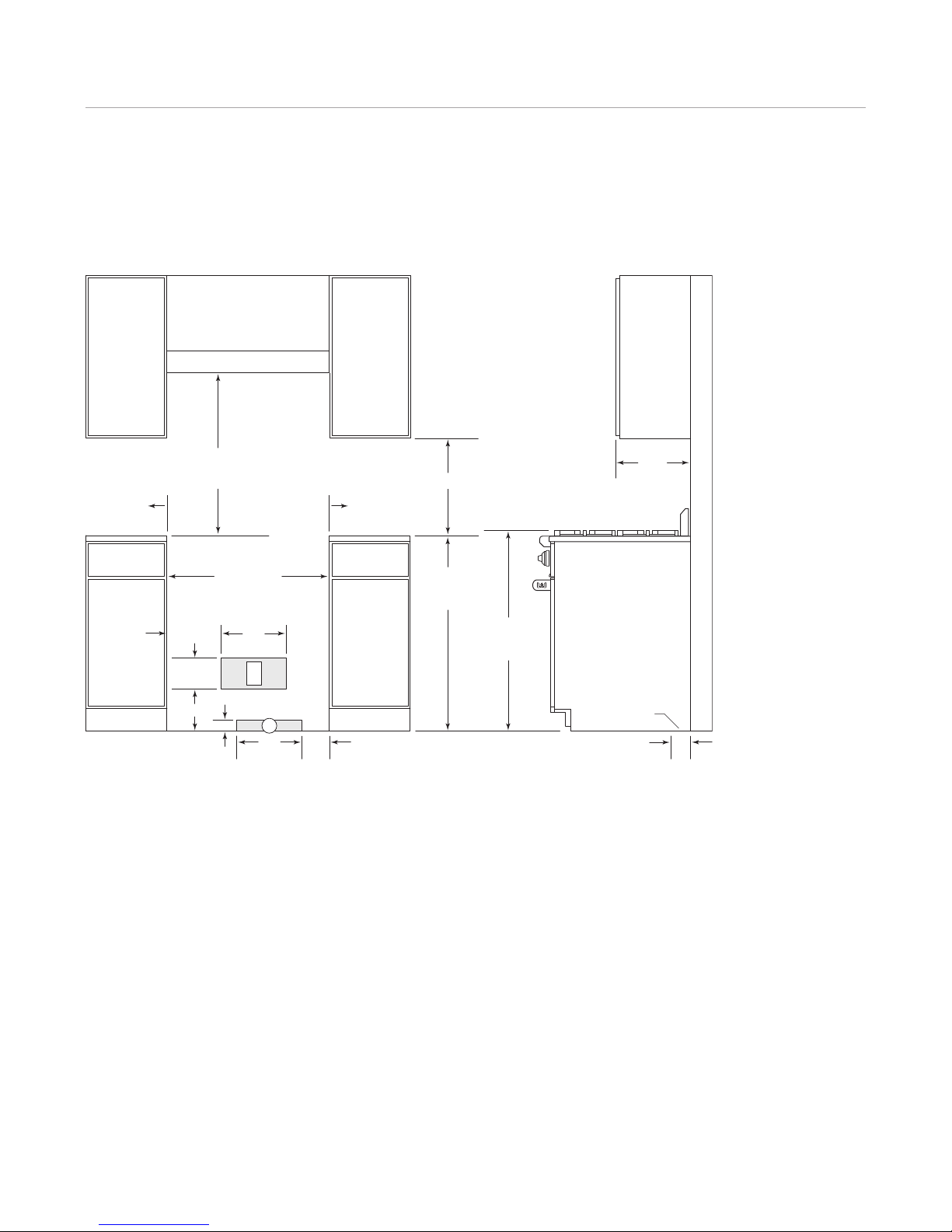
Locate the gas supply within the shaded area shown in
the illustration for your specific model on the following
pages.
IMPORTA T OTE: The supply line must be equipped
with an approved external gas shut-off valve located near
the range in an accessible location. Do not block access
to the shut-off valve. Refer to the illustration below.
Wolf natural and LP gas ranges will function up to 10,250'
(3124 m) in altitude without any adjustment. If the installa-
tion is above 10,250' (3124 m), contact your Wolf dealer
for a high altitude conversion kit.
Gas Supply Requirements
IMPORTA T OTE: The gas range must be connected to
a regulated gas supply.
IMPORTA T OTE: This installation must conform with
local codes and ordinances. In the absence of local
codes, installations must conform with the American
National Standard, National Fuel Gas Code.
The gas range is equipped for use with natural or liquid
propane (LP) gas. Conversions are required in order for
appliances designed for one gas to be operated with the
other gas. Such conversions must be performed by a Wolf
authorized service center. Make sure your gas range is
correctly adjusted for the type of gas being used.
The product rating plate has information on the type of
gas that should be used. If this information does not agree
with the type of gas available, check with the local gas
supplier. The rating plate is located under the drip pan that
supports the burner grates, inside the left side panel of the
range. Refer to the illustration below. The rating plate for
Model R482CF is located inside the right side panel.
EXPLOSIO HAZARD: Use a certified gas supply line
and install a gas shut-off valve. Securely tighten all gas
connections. Failure to follow these instructions can
result in explosion, fire or death.
Before connecting the gas supply, make sure all valves
are in a closed position. Do not connect the gas supply
to an appliance that shows any sign of damage.
Location of rating plate. Gas shut-off valve.
SHUT-OFF VALVE
OPEN POSITION
GAS SUPPLYTO APPLIANCE
RATING PLATE (INSIDE PANEL)

Gas Range Specifications 9
wolfappliance.com/specs
Gas Supply Requirements
GAS MA IFOLD PRESSURE
•atural Gas: Standard orifices are set for 5" (12.5 mb)
WC. A natural gas pressure regulator is installed.
•LP Gas: Standard orifices are set for 10" (25 mb) WC.
An LP gas pressure regulator is installed.
•Gas Supply Pressure: The maximum gas supply
pressure to the regulator should never exceed 14"
(34.9 mb) WC; .5 psi (3.5 kPa) for natural and LP gas.
The minimum line pressure is 7" (17.5 mb) WC for
natural gas and 11" (27.4 mb) WC for LP gas.
•Gas Pressure Regulator: To control and maintain a
uniform gas pressure in the gas manifold, the unit must
be used with a gas pressure regulator. The burner
orifices, etc. are sized for the gas pressure delivered by
the supplied regulator. Do not remove the regulator.
The maximum gas supply pressure to the regulator
should never exceed 14" (34.9 mb) WC; .5 psi (3.5 kPa).

Gas Range Specifications 10
301/4"(768)
OPENING WIDTH
30" (762) TO36" (914)
TO BOTTOM OF
VENTILATION HOOD**
*Minimum clearance from rough opening to combustible materials up to 18" (457) above countertop.
**36" (914) minimum clearance from countertop to combustible materials without ventilation hood.
NOTE: For island installations, 12" (305) minimum clearance from back of range to combustible rear wall above countertop.
6" (152) TO
COMBUSTIBLE*
6" (152) TO
COMBUSTIBLE*
18" (457) min
36" (914)
FLOOR TO
COUNTERTOP
12"
(305)
5"
(127)
G
2" (51)
37" (940)
TO COOKING
SURFACE
13" (330)
max
3"
(76)
LOCATION OF GAS AND
ELECTRICAL EXTENDS
ON FLOOR
SIDE
CABINET
12"
(305)
10" (254)
E
73/4"(197)
53/4"
(146)
30" (762) Gas Range
I STALLATIO

Gas Range Specifications 11
wolfappliance.com/specs
361/4"(921)
OPENING WIDTH
30" (762) TO36" (914)
TO BOTTOM OF
VENTILATION HOOD**
*Minimum clearance from rough opening to combustible materials up to 18" (457) above countertop.
**36" (914) minimum clearance, 44" (1118) for charbroiler, from countertop to combustible materials without ventilation hood.
NOTE: For island installations, 12" (305) minimum clearance from back of range to combustible rear wall above countertop.
6" (152) TO
COMBUSTIBLE*
6" (152) TO
COMBUSTIBLE*
18" (457) min
36" (914)
FLOOR TO
COUNTERTOP
12"
(305)
10" (254)
12"
(305)
5"
(127)
G
2" (51)
37" (940)
TO COOKING
SURFACE
13" (330)
max
3"
(76)
LOCATION OF GAS AND
ELECTRICAL EXTENDS
ON FLOOR
SIDE
CABINET
E
73/4"(197)
53/4"
(146)
36" (914) Gas Range
I STALLATIO

Gas Range Specifications 12
481/4"(1226)
OPENING WIDTH
30" (762) TO36" (914)
TO BOTTOM OF
VENTILATION HOOD**
*Minimum clearance from rough opening to combustible materials up to 18" (457) above countertop.
**36" (914) minimum clearance, 44" (1118) for charbroiler, from countertop to combustible materials without ventilation hood.
NOTE: For island installations, 12" (305) minimum clearance from back of range to combustible rear wall above countertop.
6" (152) TO
COMBUSTIBLE*
6" (152) TO
COMBUSTIBLE*
18" (457) min
36" (914)
FLOOR TO
COUNTERTOP
12" (305)26" (660)
12"
(305)
5"
(127)
G
2" (51)
E
73/4"(197)
53/4"
(146)
37" (940)
TO COOKING
SURFACE
13" (330)
max
3"
(76)
LOCATION OF GAS AND
ELECTRICAL EXTENDS
ON FLOOR
SIDE
CABINET
48" (1219) Gas Range
I STALLATIO

Gas Range Specifications 13
wolfappliance.com/specs
601/4"(1530)
OPENING WIDTH
30" (762) TO36" (914)
TO BOTTOM OF
VENTILATION HOOD**
*Minimum clearance from rough opening to combustible materials up to 18" (457) above countertop.
**44" (1118) minimum clearance from countertop to combustible materials without ventilation hood.
NOTE: For island installations, 12" (305) minimum clearance from back of range to combustible rear wall above countertop.
6" (152) TO
COMBUSTIBLE*
6" (152) TO
COMBUSTIBLE*
18" (457) min
36" (914)
FLOOR TO
COUNTERTOP
12"
(305)
10" (254)
12"
(305)
5"
(127)
G
2" (51)
37" (940)
TO COOKING
SURFACE
13" (330)
max
3"
(76)
LOCATION OF GAS AND
ELECTRICAL EXTENDS
ON FLOOR
SIDE
CABINET
E
73/4"(197)
53/4"
(146)
60" (1527) Gas Range
I STALLATIO

Gas Range Installation 14
Anti-Tip Bracket Installation
An anti-tip bracket is provided with the gas range. Install
the anti-tip bracket a minimum of 61/2" (165) from the
floor. If the range legs and casters are adjusted higher
than the 3" (76) minimum, the anti-tip bracket must be
mounted higher accordingly to engage the rear channel
brace on the range. The gap between the anti-tip bracket
and the rear channel brace should not exceed 1/4" (6).
Refer to the illustration below.
Install the Range
IMPORTA T OTE: Before moving the range, protect any
finished flooring to avoid damage to the floor. Secure oven
door(s) closed.
Using an appliance dolly, move the gas range into position
near the installation opening. Remove and discard packing
materials. If the oven door(s) need to be removed to
position the range, refer to oven door removal on the
following page.
Push the gas range back into the opening until it is flush
with the back wall. Be sure that it engages the anti-tip
bracket.
BACK
WALL
REAR
CHANNEL
BRACE
ANTI-TIP
BRACKET
FLOOR
61/2"
(165)
MIN
Anti-tip bracket installation.
This range can tip. Injury to persons could result. Install
the anti-tip bracket provided with the gas range.

Gas Range Installation 15
wolfappliance.com/specs
OVE DOOR REMOVAL
1) Remove the lower kickplate assembly.
2) Open the oven door all the way and insert the door
hinge pin through the hole in the appropriate hinge
arm. Refer to the illustration below.
3) Remove both upper and lower hinge retainer mounting
screws. The oven gasket may have to be moved
slightly to access the bottom screws.
4) Move the hinge retainer plate forward slightly. The
hinge retainer plate will remain on the door hinge after
the mounting screws have been removed.
5) Carefully close the oven door to approximately 60°
from horizontal and lift the door away from the oven.
A slight racking motion may be required for removal.
Oven Door Removal
IMPORTA T OTE: Remove the oven door(s) only if it is
necessary to fit the range through a tight doorway.
Removal may cause damage to the porcelain oven interior
or the door(s). Door removal should be done by a qualified
service technician or installer.
For removal, a hinge pin (supplied with the range) must be
inserted in the appropriate hinge arm. For each oven door,
only one hinge arm is spring loaded, requiring use of the
hinge pin for removal of the oven door. The hinge pin can
be found taped to the inside of the oven door.
For single oven ranges, the hinge pin will be inserted
through the hole in the right hinge arm (facing the range).
For double oven ranges, the spring hinges are located on
the outer edges of the unit. The left oven door will have
the spring hinge on the left side and the right oven door
will have the spring hinge on the right side. Refer to the
illustrations below.
SPRING HINGE
Single oven ranges. Double oven ranges.
SPRING HINGES
KICKPLATE
UPPER
MOUNTING
SCREW
HINGE
RETAINER
PLATE
HINGE
PIN
Oven door removal.
Failure to insert the hinge pin in the appropriate hinge
arm will cause damage to the range.
Do not lift or carry the oven door by the door handle.

Gas Range Installation 16
Oven Door Removal
OVE DOOR REI STALLATIO
1) Hold the oven door on both sides and position it with
door hinges aligned with openings in the oven frame.
2) Holding the oven door at an approximate 30° angle
from vertical, slide the hinges into the openings
until the bottom hinge arms drop fully into the hinge
receptacles.
3) Open the oven door to its fully opened position.
Remove the hinge pin from the appropriate hinge arm.
Refer to the illustration below.
4) Reinstall the hinge retainer plate with upper and lower
mounting screws.
5) Open and close the door completely to ensure that it is
properly installed.
6) Reinstall the lower kickplate assembly.
Gas Supply Connection
IMPORTA T OTE: All connections to the gas piping must
be wrench-tightened. Do not make connections too tight,
this may crack the regulator and cause a gas leak. Do not
allow the pipes to turn when tightening fittings.
Assemble the flexible metal connector from the gas supply
pipe to the gas pressure regulator. Determine the fittings
required depending on the size of your gas supply line,
flexible metal connector and shut-off valve. Refer to the
illustration below. If a flexible metal connector is used, be
sure the tubing is not kinked. Open the shut-off valve in
the gas supply line. Wait a few minutes for the gas to
move through the line.
GAS LEAK TESTI G
Brush a liquid detergent solution onto all gas connections
to test for leaks. Bubbles around connections will indicate
a gas leak. If a leak appears, close the gas shut-off valve
and adjust connections. Check for leaks again. Clean off
the detergent solution.
ever test for a gas leak with a match or other flame.
FLEXIBLE
METAL CONNECTOR
GAS PRESSURE
REGULATOR
SHUT-OFF
VALVE
ELBOW
ADAPTERADAPTER
NIPPLE
Gas supply line connection.
Before connecting the gas supply, make sure all valves
are in a closed position.

Gas Range Installation 17
wolfappliance.com/specs
Level the Range
IMPORTA T OTE: The top of the range must be level.
Use both the adjustable front legs and the adjustable rear
casters to level the range.
The front legs of the range are adjusted by rotating the
bottom hexagonal portion of the leg. The rear casters can
be adjusted by rotating the nut on the caster. Using the
height adjustment wrench (supplied with the range), rotate
the nut clockwise to raise the range or counterclockwise
to lower. Refer to the illustration below. The range legs and
casters allow for a 1" (25) height adjustment.
CASTER
ADJUSTMENT
HEIGHT
ADJUSTMENT
WRENCH
Rear caster adjustment.
Verify Range Operation
IMPORTA T OTE: Prior to operating the range, be sure
to read the entire Wolf gas ranges use & care guide
included with the range for important safety, service and
warranty information.
SURFACE BUR ERS
Place the burner parts on each burner base and position
the burner grates before lighting.
Surface burners of the gas range use electronic igniters.
When the control knob is pushed in and turned to the
HIGH position, the system creates a spark to light the
burner. This sparking continues until the electronic ignition
senses a flame.
To check operation of the surface burners, push in and
turn each control knob to the HIGH position. The flame
should light within four seconds.
If the burners do not light properly, turn control knobs to
the OFF position. Check that burner parts are in the
proper position. Make sure electricity is being supplied to
the range and that the gas shut-off valve is in the open
position. Check operation again, waiting at least five
minutes; if the burners still do not light properly, contact a
Wolf authorized service center.
IMPORTA T OTE: Initial lighting of the surface burners
may take slightly longer, as air in the system must be
purged before gas can be supplied to the burner.
OVE OPERATIO
Turn the oven(s) on and verify that they are coming up to
temperature. Refer to the Wolf gas ranges use & care
guide for additional information.
IMPORTA T OTE: A small amount of smoke and odor
may be noticed during the initial break-in period.

Gas Range Installation 18
Troubleshooting
IMPORTA T OTE: If the gas range does not operate
properly, follow these troubleshooting steps:
•Verify that electrical power is being supplied to the
range.
•If nuisance clicking occurs when power is supplied to
the range, check the electrical outlet for reverse
polarity.
•Check the gas supply connections to ensure that the
installation has been completed correctly.
•Check that the gas supply shut-off valve is in the open
position.
•If the range still does not operate properly, contact a
Wolf authorized service center. Do not attempt to repair
the range yourself. Wolf is not responsible for service
required to correct a faulty installation.
Range Removal
If removal of the gas range is necessary for cleaning or
service, shut off the gas supply. Unplug the range and
disconnect the gas supply line. Remove the range. Rein-
stall in the reverse order and be sure to check gas
connections for leaks.
Refer to the Wolf gas ranges use & care guide for cleaning
recommendations.
Unplug the range and disconnect the gas supply line
before removing.

Service Information
If service is necessary, maintain the quality built into your
gas range by calling a Wolf authorized service center.
To obtain the name and number of a Wolf authorized
service center, check the contact & support section of our
website, wolfappliance.com or call Wolf customer service
at 800-332-9513.
When calling for service, you will need the model and
serial numbers of the gas range. Both numbers are listed
on the product rating plate, located under the drip pan
that supports the burner grates, inside the left side panel
of the range. Refer to the illustration below. The rating
plate for Model R482CF is located inside the right side
panel.
Location of rating plate.
RATING PLATE (INSIDE PANEL)
Service Information 19
wolfappliance.com/specs
The information and images in this guide are the copyright property of Wolf Appliance, Inc. Neither this guide nor any information or images contained herein
may be copied or used in whole or in part without the express written permission of Wolf Appliance, Inc. ©Wolf Appliance, Inc. all rights reserved.
Wolf, Wolf & Design, Wolf Gourmet, W & Design and the color red as applied to knobs are registered trademarks and service marks of Wolf Appliance, Inc.
Sub-Zero, Sub-Zero & Design, Dual Refrigeration, Constant Care and The Living itchen are registered trademarks and service marks of Sub-Zero, Inc.
(collectively, the “Company Marks.”) All other trademarks or registered trademarks are property of their respective owners in the United States and other countries.

WOLF APPLIA CE, I C. P. O. BOX 44848 MADISO , WI 53744 WOLFAPPLIA CE.COM 800.332.9513
816981 REV-A 8/2010
Other manuals for 762
2
This manual suits for next models
3
Table of contents
Other Wolf Range manuals
Popular Range manuals by other brands

KitchenAid
KitchenAid KEDS100W Use and care guide

Bertazzoni
Bertazzoni HER48 6G GGV VI Installation, use & care manual

Jenn-Air
Jenn-Air SCE4320 use and care manual

Maytag
Maytag MET8820DS00 Use & care guide

Kenmore
Kenmore 790.4662 Use & care guide

Bertazzoni
Bertazzoni PRO365GASXLP Installation, use & care manual

GE
GE Coil Top Owner's manual and installation instructions

Whirlpool
Whirlpool W10196159C installation instructions

Frigidaire
Frigidaire FGGF3054MBB Use & care guide

Whirlpool
Whirlpool RF365BXP Use and care guide

GE
GE Profile PGS908DEP Dimensions and installation information

Vulcan-Hart
Vulcan-Hart G60CB-10T Specifications