Wolf WWD30-2 Service manual

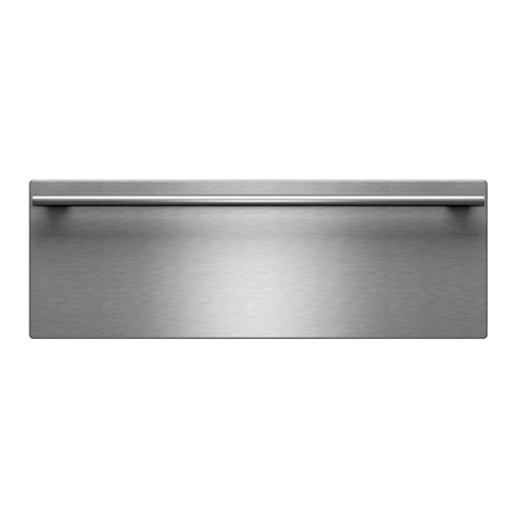
Warming Drawer WWD30-2
Installation Information
2-2
#814750 - Revision A - January, 2011
INSTALLATION INFORMATION
The Wolf Warming Drawer is designed to be set into a built-in wall or cabinet installation.
This section of the manual covers some of the installation issues that a service technician may need to know when
servicing a Wolf warming drawer. If additional installation information is needed after reviewing this section of the
manual, please refer to the installation guide or contact Wolf Appliance, Inc. Customer Service Department at (800)
332-9513.
Electrical Requirements:
NOTE:All National Electrical Code regulations must be followed. In addition, be aware of local codes and ordi-
nances when installing your service.
• Dedicated 110 to 120 Volts AC, 60Hz, 15 or 20 ampere fused electrical supply
• Separate electrical circuit serving only this appliance
• A properly grounded 3-prong receptacle
Outdoor applications require that the unit be connected to a properly grounded GFCI circuit.
Line
Voltage
(Power)
Neutral
Ground
TO AVOID SHOCK HAZARD, THE INSTALLATION SITE MUST BE EQUIPPED WITH A PROPERLY GROUNDED
3-SLOT RECEPTACLE TO MATCH THE 3-PRONG (GROUNDED) POWER SUPPLY CORD PROVIDED ON THE
APPLIANCE.
TO AVOID SHOCK HAZARD, NEVER REMOVE THE GROUND PRONG FROM THE PLUG OF THE POWER
SUPPLY CORD.
Figure 2-1. Electrical Receptacle
NOTE:
This appliance must be installed in accordance with National Electrical Codes, as well as all state, munici-
pal and local codes. The correct voltage, frequency and amperage must be supplied to the appliance from a dedi-
cated, grounded circuit which is protected by a properly sized circuit breaker or time delay fuse. The proper voltage,
frequency, and amperage ratings are listed on the product rating plate.

Installation Information
Warming Drawer WWD30-2
2-3 #814750 - Revision A - January, 2011
Cabinet Supports:
NOTE:
When the warming drawer is installed with a built-in oven, additional clearance between openings may be
required. Check that oven supports do not obstruct the interior dimensions required for the warming drawer.
NOTE:Dimensions in parentheses are in millimeters unless otherwise specified.
The warming drawer may be supported by either a solid 7/8” (22) platform or 2" (51) x 2" (51) or 2" (51) x 4" (102)
runners. The platform or runners must be level, rigidly mounted and flush with the bottom edge of the opening.
They must be able to support 200 lbs. (90.7 kg).
NOTE:
Make sure that the platform or runners are level. There is no way to level the warming drawer once it has
been installed.
Warming Drawer Installation:
Install a 2" (51) x 2" (51) or 2" (51) x 4" (102) anti-tip block
against the rear cabinet wall.
Turn power off to the electrical outlet.
Slide the left corner of the warming drawer into the open-
ing.
NOTE:A 6 foot power cord is supplied with the unit.
Depending on the outlet location, the unit can be set in
front of opening and plugged in.
If the electrical outlet is installed inside the opening, plug
the power cord into the outlet. The excess cord should be
coiled and secured directly behind warming drawer. If the
outlet is located in an adjacent cabinet, thread the power
cord through the hole in the cabinet wall. Push the drawer
back into the opening until the front flange is flush with
the cabinet front. Make sure the power cord does not get
trapped under the warming drawer.
Open the warming drawer to its full extension. Then, drill pilot holes in each corner of the warming drawer through
holes in the side frame and install the wood screws provided with the unit. (See Figure 2-2)
Figure 2-2. Drilled Pilot Holes for Securing Unit
Pilot Holes
MODEL WWD30
with Stainless Steel Drawer & Integrated Front
Overall Width 29 7/8" (759)
Overall Height 10 3/8" (264)
Overall Depth 26 1/4” (689)
Overall Depth (behind frame) 22 3/4" (578)
Minimum Cabinet Width 30" (762)
Minimum Cabinet Depth 24" (610)
Minimum Base Support 200 lbs (91 kg)
Opening Width 28 5/8" (727)
Opening Height 9 1/8" (232)
Opening Depth 23 7/8” (606)
Dimensions may vary to +
–1/8" (3).
Allow 3/8” (11) Additional depth for cord thickness
22
3
/
4
"
(578)
9"
(229)
10
3
/
8
"
(264)
29
7
/
8
"
(759)
26 1/4” (667)
OVERALL DEPTH
OVERALL WIDTH BEHIND FRAME
Figure 2-4. Overall Cabinet Dimensions
Installation Specifications:
The following pages provide the overall dimensions, finished rough
opening dimensions and electrical placement for the Wolf warming
drawer with stainless steel drawer front. For information on integrat-
ed Drawer Fronts, see the installation instructions provided with the
product.
Wolf recommends using a 33" (838) wide cabinet for the warming
drawer with stainless steel drawer front. A minimum 30" (762) wide
by 24" (610) deep cabinet is required with a minimum base support
of 200 lbs (91 kg). (See Figure 2-3 and 2-5)
Figure 2-3. Overall Unit Dimensions
Anti-Tip Block

Warming Drawer WWD30-2
Installation Information
2-4
#814750 - Revision A - January, 2011
Undercounter Installation:
For undercounter installations, 23 1/2"
(597) from the bottom of the warming
drawer opening to the floor is recom-
mended. Electrical can be installed
anywhere except location shown. A
minimum of 5" (127) above the floor
or 1" (25) above the toe kick.
The Wolf warming drawer with stain-
less steel drawer front may be
installed below an electric or gas
cooktop, provided the warming drawer
is fully enclosed, top and bottom.
Refer to installation instructions for
the cooktop for additional specifica-
tions. Dimensions will vary according
to the specific installation.
(See Figure 2-5)
Warming Drawer Installation with Built-In Oven and/or Microwave:
The warming drawer may be installed in combination with a Wolf built-in oven and/or microwave, provided the
warming drawer is fully enclosed, top and bottom. See Figure 2.6
NOTE: Dimensions will vary according
to the specific installation.
The Wolf warming drawer is designed
and agency approved for installation
with Wolf built-in ovens and/or
microwaves. See the label attached to
the top of the warming drawer for
approved models.
The warming drawer platform must be
able to support 200 lbs. (91 kg). It must
be a minimum of 1" (25) above the toe
kick to allow for the overlap of the warm-
ing drawer trim.
NOTE:
Additional clearance between
warming drawer and oven openings may
be required. Check that oven supports
do not obstruct the interior dimensions
required for the warming drawer.
When the warming drawer is installed
below a built-in oven, a minimum of
2 3/8" (60) between warming drawer
and oven openings is required for clear-
ance of overlaps. When installed above
a built-in oven, a minimum of 7/8" (22) is required.
NOTE:
When the warming drawer is installed above a built-in oven, a 7/8" (22) platform is required to allow for
clearance of overlaps.
24"
(610) min
OPENING DEPTH
*P latform mus t s upport 250 lbs
(113 kg)
.
NO T E : L ocation of electrical s upply within oven opening may require a dditional ca binet depth.
FRONT VIEWSIDE VIEW
28
5
/
8
"
(727)
WARMING DRAWER
OPENING WIDTH
28
1
/
2
"
(724)
OVEN OPENING WIDTH
E
E
MICROWAVE
OPENING
27
3
/
16
"
(691)
1
1
/
2
"
(38) min
E SERIES
1"
(25) min
L SERIES
9
1
/
8
"
(232) 3
/
4
"
(19)
min
PLATFORM*
E
E
5"
(127)
4"
(102 )
ANTI-TIP BLOCK
DIMENSION
WILL VARY*
*Dimens ion must accommodate height of anti-tip block and drawer face overlap.
NOT E : L ocation of electrical s upply within opening may require additional cabinet depth. Dashed line repres ents profile of unit.
FRONT VIEWSIDE VIEW
E
24"
(610) min
CABINET DEPTH
28
5
/
8
"
(727)
OPENING WIDTH
PLATFORM
9
1
/
8
"
(232)
OPENING HEIGHT
10
3
/
8
"
(264)
23
1
/
2
"
(597)
TYPICAL
36"
(914)
FLOOR TO
COUNTERTOP
Figure 2-5. Undercounter Installation
Figure 2-6. Installation with Built-In Wall Oven and/or Microwave

Installation Information
Warming Drawer WWD30-2
2-5 #814750 - Revision A - January, 2011
Recessed or Flush Inset Installation
In addition to the standard installation the warming drawer with E series drawer front can be installed in a recessed
or flush inset application. A recessed installation requires the cabinetry be recessed by 3/16" (5) so the collar is flush
with the cabinet face frame but the drawer front will sit proud. A flush inset installation requires the drawer collar and
front panel be recessed to be flush with surrounding cabinetry. Refer to illustrations on the following pages for mini-
mum cabinet dimensions for your specific installation.
Install Recessed Cleats and Platform
For a recessed or flush inset application, you will need to
install a recessed platform and cleats into the opening.
Proper recess of the platform and cleats is critical to the
function and esthetics of the warming drawer installation.
The depth of the platform may increase with the cabinet
depth. Be sure to rigidly mount the platform so that it
can support a minimum of 200 lbs (91 kg). (See Figure 2-7)
Mounting holes will need to be drilled in the back of the
drawer front panel. Holes should be drilled on site to
ensure proper fit and gaps are achieved. A drilling
template is provide with the integrated drawer front.
NOTE:
Be sure to finish the inside lip of the opening and the front face of the platform and cleats. These areas
may be visible when the drawer is open.
NOTE:
Be aware of the location of the mounting holes on the warming drawer frame to make sure screws used to
attach the cleats do not interfere with screw holes for mounting the warming drawer.
Flush Inset Installation Under Counter
PLATFORM
TOP CLEAT
SIDE CLEAT
CABINETRY
OPENING
CLEATS AND PLATFORM
RECESSED
3
/
16
"
(5)
R ec es s ed applic ation. F lus h ins et applic ation.
PLATFORM
TOP CLEAT
SIDE CLEAT
CABINETRY
OPENING
CLEATS AND PLATFORM
RECESSED
3
/
16
"
(5)
PLUS THICKNESS
OF DECORATIVE PANEL
Figure 2-7. Install Platform and Cleats
DIMENSION
WILL VARY*
23
1
/
2
"
(597)
TYPICAL
*Dimension must accommodate height of anti-tip block and drawer face overlap.
NOTE : Dimensions provided allow for
1
/
4
" (6) reveal for proper air flow. Location of electrical supply within opening may require additional
cabinet depth. Das hed line repres ents profile of unit.
FRONT VIEWSIDE VIEW
24"
(610) min
CABINET DEPTH
30
3
/
8
"
(772)
FLUSH INSET WIDTH
28
5
/
8
"
(727)
OPENING WIDTH
7
/
8
"
(22)
PLATFORM
7
/
8
"
(22)
TOP AND SIDE CLEATS
36"
(914)
FLOOR TO
COUNTERTOP
10
7
/
8
"
(276)
FLUSH INSET
HEIGHT
9
1
/
8
"
(232)
OPENING HEIGHT
E
E
SIDE CLEATS
24
(610) min
FLUSH INSET
DEPTH
1"
(25)
TOP VIEW
ANTI-TIP BLOCK

Warming Drawer WWD30-2
Installation Information
2-6
#814750 - Revision A - January, 2011
Flush Inset Tower Installation
25"
(635) min
CABINET DEPTH
30
3
/
8
"
(772) min
FLUSH INSET WIDTH
SIDE CLEATS
24
3
/
4
"
(629) min
FLUSH
INSET
DEPTH
1"
(25)
*
Platform mustsupport250 lbs
(113 kg).
NOTE : Location of electrical supply within oven opening may require additional cabinet depth. Dashed line represents profile of unit.
FRONT VIEWSIDE VIEW
TOP VIEW
10
5
/
8
"
(270)
FLUSH INSET
HEIGHT
9
1
/
8
"
(232)
OPENING HEIGHT
E
1"
(25)
PLATFORM
28
5
/
8
"
(727)
WARMING DRAWER
OPENING WIDTH
17"
(432)
OPENING
HEIGHT
18
1
/
2
"
(470)
FLUSH INSET
HEIGHT
27
1
/
2
"
(699)
STANDARD MICROWAVE
OPENING WIDTH
E
28
1
/
2
"
(724)
E SERIES OVEN
OPENING WIDTH
11
/
16
"
(17)
TOP CLEAT
9
/
16
"
(14)
PLATFORM*
1"
(25)
SIDE CLEATS
E
E
5"
(127)
4"
(102)
27
3
/
16
"
(691)
OPENING
HEIGHT
28
1
/
8
"
(714) min
FLUSH INSET
HEIGHT
1
11
/
16
"
(43)
PLATFORM
INSTALLATION WITH STANDARD MICROWAVE AND E SERIES OVEN

Installation Information
Warming Drawer WWD30-2
2-7 #814750 - Revision A - January, 2011
Flush Inset Tower Installation
25"
(635) min
CABINET DEPTH
30
3
/
8
"
(772) min
FLUSH INSET WIDTH
SIDE CLEATS
24
3
/
4
"
(629) min
FLUSH
INSET
DEPTH
1"
(25)
*
Platform must support 250 lbs
(113 kg).
NOTE : Location of electrical supply within oven opening may require additional cabinet depth. Dashed line represents profile of unit.
FRONT VIEWSIDE VIEW
TOP VIEW
10
5
/
8
"
(270)
FLUSH INSET
HEIGHT
9
1
/
8
"
(232)
OPENING HEIGHT
E
1"
(25)
PLATFORM
28
5
/
8
"
(727)
WARMING DRAWER
OPENING WIDTH
18
7
/
8
"
(479)
OPENING
HEIGHT
20
1
/
8
"
(511)
FLUSH INSET
HEIGHT
27
1
/
2
"
(699)
CONVECTION MICROWAVE
OPENING WIDTH
E
28
1
/
2
"
(724)
E SERIES OVEN
OPENING WIDTH
1
/
2
"
(13)
TOP CLEAT
9
/
16
"
(14)
PLATFORM*
1"
(25)
SIDE CLEATS
E
E
5"
(127)
4"
(102)
27
3
/
16
"
(691)
OPENING
HEIGHT
28
1
/
8
"
(714) min
FLUSH INSET
HEIGHT
1
5
/
8
"
(41)
PLATFORM
INSTALLATION WITH CONVECTION MICROWAVE AND E SERIES OVEN

Warming Drawer WWD30-2
Installation Information
2-8
#814750 - Revision A - January, 2011
Flush Inset Tower Installation
27
3
/
16
"
(691)
OPENING
HEIGHT
28
1
/
8
"
(714) min
FLUSH INSET
HEIGHT
28
1
/
2
"
(724)
E SERIES OVEN
OPENING WIDTH
25"
(635) min
CABINET DEPTH
30
3
/
8
"
(772) min
FLUSH INSET WIDTH
28
1
/
2
"
(724)
DRAWER MICROWAVE
OPENING WIDTH
E
7
/
8
"
(22)
TOP CLEAT
9
/
16
"
(14)
PLATFORM*
5
/
8
"
(16)
PLATFORM
SIDE CLEATS
24
3
/
4
"
(629) min
FLUSH
INSET
DEPTH
1
1
/
4
"
(32)
FOR MICROWAVE
1"
(25)
FOR
OVEN
AND WARMING
DRAWER
*
Platform mustsupport250 lbs
(113 kg.
NOTE : Location of electrical s upply within oven opening may require additional cabinet depth. Dashed line repres ents profile of unit.
FRONT VIEWSIDE VIEW
TOP VIEW
14
3
/
4
"
(375)
OPENING
HEIGHT
15
3
/
8
"
(391)
FLUSH INSET
HEIGHT
1"
(25)
SIDE CLEATS
10
5
/
8
"
(270)
FLUSH INSET
HEIGHT
9
1
/
8
"
(232)
OPENING HEIGHT
E
1"
(25)
PLATFORM
28
5
/
8
"
(727)
WARMING DRAWER
OPENING WIDTH
E
E
5"
(127)
4"
(102)
INSTALLATION WITH DRAWER MICROWAVE AND E SERIES OVEN
Other manuals for WWD30-2
2
Table of contents
Other Wolf Warming Drawer manuals