Wolfgang Warmbier PGT130.DT User manual

User’sManual–PGT®130.DT
Part No.:7100.PGT130.DT
Page1/ 21 V12/2020
User’sManual
Personnel Grounding Tester
PGT®130.DT
V1.2

User’sManual–PGT®130.DT
Part No.:7100.PGT130.DT
Page2/ 21 V12/2020
Tableofcontents
Tableof contents.................................................................................................................................... 2
Introduction ............................................................................................................................................ 3
Important Notice .................................................................................................................................... 3
Scope of Delivery................................................................................................................................... 4
Installation.............................................................................................................................................. 4
InitialOperation - Local.......................................................................................................................... 6
InitialOperation viaNetwork.................................................................................................................. 7
Configuration...................................................................................................................................... 8
Operation ............................................................................................................................................. 13
Devicespecification:............................................................................................................................ 15
Limitsand modes............................................................................................................................. 15
TechnicalData.................................................................................................................................. 15
Calibration............................................................................................................................................ 16
Accessories ......................................................................................................................................... 17
Wastedisposal..................................................................................................................................... 18
DataExport Interface........................................................................................................................... 19

User’sManual–PGT®130.DT
Part No.:7100.PGT130.DT
Page3/ 21 V12/2020
Introduction
The PGT®130.DTisacompact testingsystem for checking Personnelgrounding withESDshoes,
wrist strapssystemsand smocks accordingtoIEC 61340-5-1andANSI ESDS20.20.
The user identification ispossibleviaintegrated RFIDreader or viaany externalHID-compatible
USBinput devicee.g. barcode scanner, keyboardor magneticstripe reader.
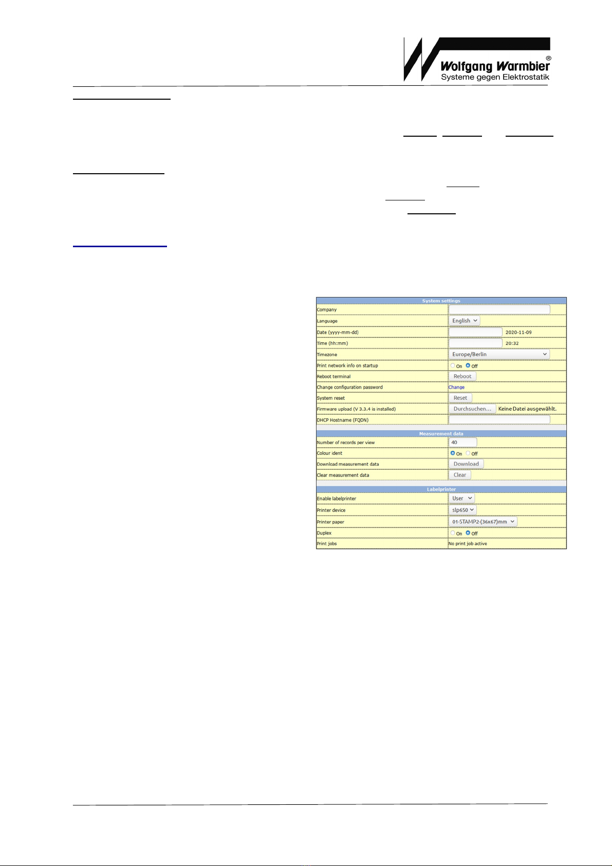
Multipledevices can be networked together and managedby the DataTermDsoftware. User data
and measurement datacanbe managed centrally.
General notice:
Persons withpacemakeror pregnant women shouldconsult adoctor beforeusingthe device.
The PGT®130.DTmust beoperatedwiththe originallysupplied power supply.
The maximum USB cablelengthis2m
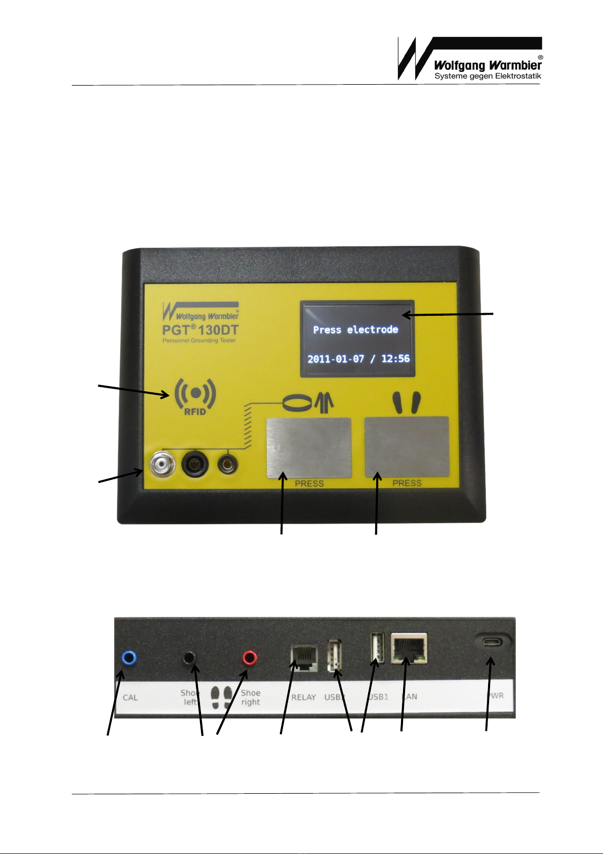
Noticeformeasurement:
The sensor platemust be pressedwithseveralfinger tips at once.
After ashort timeperiod the measurement values aredisplayed.
Keepthesensorplatepressedduring thecompletemeasurement.
NoticeforRFID:
The integrateduniversalRFIDreader can readthe frequencies125 kHz/ 134,2kHzand
13,56 MHz.Thisincludes common transponder typeslikeEM4x, HITAG, ISO14443A,
ISO14443B, ISO15693.
Bydefault the uniqueserialnumber of the presentedcardisreadinhexadecimalnotation.
Please contact us for individualconfigurationif yourcompany cardsarenot detected or if
you need different dataofthe cardfor personnelidentification.
If you‘reusing dualcards (ID-cards withtwodifferent transponders) your cardcan be
detected withtwodifferentID‘s. Contact us toadjustthe reader toyour requirements.
ImportantNotice
Please read the following instructions carefully.
1. PGT®130.DTcleaning
§Switch off the device by disconnecting the power supply
§Spray anon-solvent basedcleaner ontoasoft fabricand wipethe surface carefully
2. Don‘t remove the cover,don‘t trytorepair the device yourself
3. Observe the operatingconditions
4.TheUSB cablelengthmust not exceed 2meter
5. Use onlythe power supply, which was included inthe scope of delivery

User’sManual–PGT®130.DT
Part No.:7100.PGT130.DT
Page4/ 21 V12/2020
ScopeofDelivery
·PersonnelGrounding Tester PGT®130.DT
·Power supply(EU/ US)
·Footwear electrode
·User’smanual
·Calibrationcertificate(German / English)
Installation
Device overview
Rear Connections
ColourDisplay
Internal
RFIDReader
Sensor plate
Wrist strap
power
supply(DC)
LANCalibration
socket
Footwear
electrode
connectors
USB
1 +2
Relay
output
Sensor plate
Shoes
Connections
Wrist / Smock

User’sManual–PGT®130.DT
Part No.:7100.PGT130.DT
Page5/ 21 V12/2020
Connections
PWR
Power supply
LAN
Ethernet Interface
USB1/ USB2
Externalcomponent connectors
•Optionalexternalinput device (needs tobe connected inUSB2)
•Temperature/HumiditySensor
•Labelprinter
•Beacon light
RELAY
Door opener output (SolidStateRelay)
Switches if the measurement iswithinthe limit valuesand avaliduserwas identified.
Contact between pin3and4.
Contact-less, solidstaterelay toswitch 24V/DC(16V/AC) ohmicload up to 2A.
Output contact: Pin3and 4
Footwear electrode
Cableoutlet isconfigurableto
(middle, right andleft)
Dimension:
500 x350x9mm (WxLxH)
Electrode:
2x(300 x160 mm)
Cablelength:
2,5
m
Separator:
optional
Footwearelectrodewith optionalred separator
Thisoutput isdesigned toswitch ohmicloadsdirectly.
Toswitch inductive loads, it isrequired toprotect the relay from over-voltage surge withrecovery
diode or RC-combination/ snubber.
Schematicdrawingof the relay

User’sManual–PGT®130.DT
Part No.:7100.PGT130.DT
Page6/ 21 V12/2020
Installation
1. Connect the footwear electrode tothe red and blacksocket.
2. If you wishtouse external input deviceconnect it tothe USB2socket.
3. Connect the externalTemperature/Humiditysensor viasupplied extension cabletothe
device if applicable.
4. If you’reusing printer functionalityconnect the labelprinter toafree USB port.
5. If applicable, connect the networkcabletothe LANsocket.
6. Connect the suppliedpower supplytothe PWRsocket.
Use onlytheoriginal powersupplywhichwas includedinthescopeof delivery.
Rebooting isrequiredtoactivatenew connectedUSBdevices.
InitialOperation -Local
If you operatethe deviceinstand-aloneyou can configureit infront viadisplay.The symbolsfor
wrist and shoearetouchsensitive.
Info: Thisoption canbe disabled viaweb interface settings [Device settings –Configbuttons]
Press the left button for at least 3seconds
Keep the left button pressed and tap the right buttonat least 4times back-to-back
The device switches toconfiguration mode.The configuration modedoestime-out automatically
after 5minutes without operation, settings will stored.
Browse throughthe parameter menu withthe left button.After the last parameter the
configuration modedoesexit andthe settingsarestored.
Switch between the availablesettings withthe rightbutton.

User’sManual–PGT®130.DT
Part No.:7100.PGT130.DT
Page7/ 21 V12/2020
Parameter Funktion
Language Devicelanguage selection
English
, German, Spanish, French
Voltage Measurevoltage
30V, 50V,
100V
Measuremode Measuremodes
AND- Shoe andwrist required
OR - Shoeor wrist measurement
WRIST- Onlywrist measurement required
SHOE
-
Onlyshoe
measurement required
Buzzer Internalbuzzer
ON
, OFF
LowLimit Lowlimit for shoe measurement (100k ) and wrist strap system
measurement (750k )
ON
, OFF
High Limit Shoe High limit for shoe measurement
20 M
, 35
M
,
70
M
,
100 M
High Limit Wrist strap High limit for wrist strap / smock measurement
35 M
, 100
M
, 1000
M
* (*100VMeasure voltage required)
Hands-free mode Measurement without hands (shoe toshoe)
ON,
OFF
Relay pulselength Relay pulselength
1s
, 2s, 3s
InternalRFID InternalRFIDreader
ON
, OFF
Calibration
Measurement display fordevice calibration
Default settings areinbold
InitialOperation viaNetwork
The PGT®130.DTisreadywithin50 seconds after plugging-inthe power supply. If the Ethernet
cableisconnected, the device tries toconfigureitsnetworkbyDHCP.ThereforeaDHCPserver
shouldbe availablewithinthe network.Alabelindicating the assigned IPAddress willbe printed on
system start-up if the label printer isconnected.The IP-Address isdisplayedtemporarilyonthe LCD
displayas well.
System clockcan beset byDHCPas well(042 timeserver).
If Internet access isavailable, the system clock willsynchronized withaNTPtimeserver.
The configured DHCPhostnamewillbe sent tothe DHCPserver if available.
If DHCPconfiguration failsthe default IP-Address 192.168.1.1 willbe used.
It ispossibletoenter adifferent IP-Address manually.
Entering afixed IP-Addresswill deactivateDHCP.
Toconfigurethe DataTerminalenter the assignedIP-Address intoyour browser'sURL-field.
The first access openstheconfigurationpagewithout asking for apassword.
Adjust and safethe settings tocontinue.

User’sManual–PGT®130.DT
Part No.:7100.PGT130.DT
Page8/ 21 V12/2020
Important settings:
The timezone, dateand timemust first be set inSystem settings
After saving the settings and logging inyou find the optionalsections Device,NetworkandAdvanced
inthe Configuration menu.
Optional settings:
•Configuremeasurevoltage, measuremode andlimit values insection Device.
•If desired youcan configureafixed IP-Address insection Network.
•Settings for User datasynchronization areavailableinsectionAdvanced.
Configuration
Administrationpasswordisrequired for configuration.Thedefault loginisUser: admin Password:
admin.The user canchange the password.
Systemsettings
·Company nameor independent text. This
will be printed on the first line of each label.
The user IDcan beprintedinstead, if user
identificationisenabled and thisfieldis
blank.
·WEB-interface language
·Set the date
·Set the time
·Select current timezone
·Print assigned IP-Addressafter each
system start-up
·Reboot the terminal
·Change theconfiguration password
·System reset (measurement dataand
settings willbe erased)
·Firmwareupload
·DHCPhostnameconfiguration
Measurement data
·Select amount of records tobe viewed in
measurement dataview
·Enableor disablecolored markingof failed test
·Download measurement dataas CSV file
·Clear allmeasurement data
Label printer
·Enableor disablethe Labelprinter. Select "ID<99"toprint the
·labelonlyif the entered user IDhas less than threecharacters.
·Printer and paper selection
·Deletepending print jobs

User’sManual–PGT®130.DT
Part No.:7100.PGT130.DT
Page9/ 21 V12/2020
Device settings
·Measurevoltage: 30V, 50V, 100V
·Measuremodes:
oAND- Shoe andwrist measurement required
oOR - Shoemeasurement
oWRIST- Onlywrist measurement required
oSHOE- Onlyshoe measurement required
·Internalbuzzer: ON, OFF
·Lowlimit shoe(100k ) andwrist (750k ) ON, OFF
·Upper Limit Shoe
o20 M , 35M , 70 M , 100 M
·Upper limit Wrist
o35 M , 100M , 1000M (100Vmeasure
voltagerequired)
·Measurement without hands (shoe toshoe)
oON, OFF
·Relay pulselength: 1s, 2s, 3s
·InternalRFIDreader: ON, OFF (OFF= externalor no input device)
·Enable/Disableconfiguration buttons: ON, OFF(Tempering protection)
Manual IP-AddressConfiguration
·Log intothe configuration page withyour usernameand password.
·Select Configuration-> Network
·Enter the desiredIP-Address andassociated Netmask carefully.
·If required, agateway address can be
·defined.
·Savethe settingsand reboot the
device with Configuration->
Reboot.
Recovery
If you'veenteredanincorrect IP-Address, thedevice isnot accessiblewithinthenetworkany
more.
Torectifythe faultysettingskeep the right button pressed during start-up. Hereby the
manualsettings areignored and the device will start withnetworkdefaults.

User’sManual–PGT®130.DT
Part No.:7100.PGT130.DT
Page10 / 21 V12/2020
ExtendedConfiguration
Settings for measurementdataretrievalanduser datasynchronizationareavailablehere.
It isrecommended touseHTTPS insteadof HTTPassecurecommunication for measurement and
user datatransfer.You canadditionallydefine apasswordfor the communication.
·Access password: Passwordfor the connection
·User-IDcheck:Access for onlypersonsdefined inthe user database (noanonymous
access)
·Deletethe user database
·Uploaduser dataviaCSV file.The filemust containthe columnIDandName.
Lines with#at the beginning are
ignored.
·Use SemicolonorTab-Stopas
Separator and fileextension TXTor
CSV. Character coding isUTF-8
·Download user dataas TEXT/CSV
file
Optional beacon
·Signallight timing
·Signallight buzzer settings
Sysinfo
·Display of softwareversions
·System time
·Device'sIPand MAC-address
·Last measurement poll-time
·Last sync of user dataandamount of
records
·USBdevicestatus
Externalinputdevice on USB2
Instead of using the internalRFIDreader youcan connect an externalinput device likebarcode
scanner, magneticstripereader or keyboard.
Inthiscase you must disablethe internalRFIDreader inthe configuration menu and restart the
device. If avalidexternalinput device isdetected during start-up the user identification will be
handledby that device.
Validinput devices aredeviceswhichidentifythemselveson the USB-Bus as Human Interface
Device(HID). Onlyone HID-Device canbe connected at the sametime.Use port USB2for this
because it provides amaximum power of 500mA.
The expiration timefor the User-IDis10 seconds.

User’sManual–PGT®130.DT
Part No.:7100.PGT130.DT
Page11/ 21 V12/2020
Testdata
Test dataviewisthe mainentrypage.
Aconfigurablenumber of records are
displayed, including test data, date, time
and test result. Measurement dataview
isupdated every20 seconds.
The current temperatureand the relative
humidityisrecorded if the T/H-Sensor is
connected.
For identified usersthe user IDshows
up. If the IDislinked toausername,
then the usernameisdisplayed instead.
History
One month'stest datastorage is
separatedfor each day. Use the
browser'sprinting functiontoprint.

User’sManual–PGT®130.DT
Part No.:7100.PGT130.DT
Page12 / 21 V12/2020
Table-userdata:
Field Content Format
userid User-ID String - max. 30 characters
(ASCII 32
-
127)
name
Name
String
-
max. 30 characters
optional
profile Measureprofile Integer
0=Arbitrary
1= Shoe
2= Wrist
3= Shoe andwrist
4= Singleshoe
6= Wrist and singleshoe
8= Wrist withglove
print Labelprint Integer
0= off
1= on
View withMS-EXCEL:
Datastored asCSV or TXTfile:
Additional Option:
profile
If thereisaspecificnumber inthe field“profile”, thenthe relevant measurement ismandatoryfor this
user
print
If thereisthe number “1” inField“print” then the labelprint isactivated for a“passed” test of the
specificperson. Inthe printer configuration thesettingmust be selectedto“User”.

User’sManual–PGT®130.DT
Part No.:7100.PGT130.DT
Page13 / 21 V12/2020
Special Function:
Service-access withoutmeasurement validation
Userswhose names aremarked withaleadingasterisk "*" areallowed topass even if the
measurement valuesareout of range.The signalwillindicate“yellow” instead of “green” and no
labelwill beprinted.
FirmwareUpdate
Use Configuration-> Firmwareupload-> Search toselect the appropriateBINfile. Onlynewer
versions canbe installed, downgrade isnot possible. Use the Save settings button on the bottom of
the page and wait until theupdatehasfinished(at least 3minutes).
Donot disconnect thepowersupplyduringtheupdate.
Operation
Test withuseridentification
If user identification isenabledthe measureprofileiscontrolledby the field“profile” of the user
record. Device default settings areusedif no user profileispresent.
1. Identifyyourselfwitharegistered RFIDcard.
2. Arrowindicatorsshowtherequiredmeasurement according tothe specified user profile.
Left –wrist strap / right - shoes.
3. Touch onlyone sensor platefor measurement.
Test without useridentification
If user identification isdisabled the devicesettings areused.
Touch theleft sensor for wrist measurement, or the right sensor for shoe- or combined
measurement.
Modes / Profiles
Wrist test
Put on the Wrist strap / smock withcoil cordandconnect the coilcordtotheappropriatesocket on
the left side of the PGT®130.DT.Touch the left sensor.After ashort measurement timethe color test
result (green= pass, / red = fail) and the measurement values aredisplayed.
Shoetest
Stand onthe footplatewithbothshoes.
Touch theright electrode.After ashort measurement timethe color test result (green= pass, / red =
fail) andthe measurement valuesaredisplayed.
Shoeand wrist test
Put on the Wrist strap / smock withcoil cordandconnect the coilcordtotheappropriatesocket on
the left side of the PGT®130.DT. Stand on the footplatewithbothshoes.
Touch theelectrode.After ashort measurement timethe color test result (green= pass, / red = fail)
and the measurement values aredisplayed.

User’sManual–PGT®130.DT
Part No.:7100.PGT130.DT
Page14 / 21 V12/2020
Singleshoetest
Thisoperating mode for handicapped personnelwithone artificialleg isonlyavailableif user
identificationisenabled.
Stand onthe footplate. Identifyyourselfwiththe IDcardand thentouch the right sensor.After ashort
measurement timethe color test result (green= pass, / red = fail) and the measurement valuesare
displayed.
Glove test
Thisoperating mode isonlyavailableif user identification was enabled.
Put on the Wrist strap / smock withcoil cordandconnect the coilcordtotheappropriatesocket on
the left side of the PGT®130.DT.
Identifyyourselfwiththe IDcardand then touch theleft sensor withthe glove.
After ashort measurement timethe color test result (green= pass, / red = fail) and the measurement
values aredisplayed.
Hands-free test (shoetoshoe)
Thisoperating mode isgloballyselected withindevice settingsand affectsallmeasurementsonthis
device.
The measurement startsautomaticallywhen thefootplatewas approachedwithbothshoes.After a
short measurement timethe color test result (green= pass, / red = fail) and themeasurement values
aredisplayed.
Inthisoperating mode wrist test isonlyavailableif user identificationisenabled.
If user identification isenabledidentifyyourself withthe RFIDcardbeforeapproaching thefootplate.
For additionalWrist test put on the wrist strap/ smockwithcoilcordas well. connect the coil cordto
the appropriatesocket on the left side of the PGT®130.DT.
Identifyyourselfwiththe RFIDcard, then approachthe footplate.

User’sManual–PGT®130.DT
Part No.:7100.PGT130.DT
Page15 / 21 V12/2020
Devicespecification:
Limitsand modes
Test voltage
Test voltage (no
-
loadoperation)
100V/ 50V/ 30VDC
Upperlimits Measurerange
Wrist / Smock
35 M
, 100
M
, 1
G
Footwear
-
each
shoe
20 M
, 35
M
,
70
M
,
100 M
Footwear
-
inseries
40 M
, 70
M
,
140M
, 200
M
Lowerlimits Measurerange
Wrist / Smock
750 k
,
OFF
Footwear
100 k ,
OFF
TechnicalData
Powerconsumption:
ca. 1,6W (5V/DC)
Powersupply: AC 100–240V50-60Hz/ DC5V, 2,5A
Operatingconditions: 10 - 40°C bis75%r.F.
Storageconditions: 10 - 60°C bis75%r.F.
Display:
Result display
Colo
u
r display
Measureranges: Wrist 100 k - 200 M ± 5%
200 M
-
1
G
± 10%
Footwear
100 k
-
200
M
± 5%
Interface:
Wrist
Snap10
mm, 2xsocket 4
mm
Footwear
2xsocket 4
mm (red/black)
Door opener
Westernsocket 6pol. RJ12
LAN
Networkconnector RJ45
Calibration
Socket 4
mm (blue)
USB1max. 100mA
USB2max. 500mA
(max. 2
m cable
length)
Output 1xSolidStateRelay 24V/DC(16V/AC) 2A- Ohmicload.
Externalprotection circuit for switching
inductiveloads isrequired!
Modes: Singletest „OR“
Doubletest „AND“
OnlyWrist strap, Onlyshoes
Hands
-
Free (Shoes inseries)
Measuretime:
< 2Sec.
Dimensions:
200 x150x63 mm
Weight: 500 g
Footwearelectrode:
500 x350x9mm
Weight: ca. 2kg
Safetyclass:
IP20

User’sManual–PGT®130.DT
Part No.:7100.PGT130.DT
Page16 / 21 V12/2020
Serial number: Labelon housing side
Design: For indoor operation
Tabletop / Wallmounting(withoptionalwallmounting bracket)
compliant
Calibration
Totest the instrument accuracy youcan usethe optional
availableCalibration Unit for PGT130.DT.
Detailed instructions canbe found inthe Calibrationunit’s user’s
manual.
Type: PGT®130.DT.CU
Part No.: 7100.PGT130.DT.CU

User’sManual–PGT®130.DT
Part No.:7100.PGT130.DT
Page17 / 21 V12/2020
Accessories
Wallmounting bracket
for devicemounting besidedoors.
Type: PGT®130.DT.WH
Part No.: 7100.PGT130.DT.WH
Temperature/Humidity Sensor
The current temperatureand the relative humidityisrecordedif the
T/H-Sensor isconnected.
The T/H-sensor must be connected viasupplied extension cabletothe
device.
Type: DT-USB-TF
Part No.: 7100.PGT130.DT.TF
Label Printer
Labelprintingfor passedtestswithtest resultsand
measurement values.
The device iscompatiblewithSeiko Labelprinter
SLP450and SLP650
Type: SLP650
Part No: 7100.PGT120.COM.D.2
Following consumables areavailablefor the LabelPrinter:
Self-adhesivelabels- color: white.Type: SLP-STAMP2(36x67mm)
Part No.: 7100.PGT120.COM.D.3
Beacon (Visual Signal Indicator)
Red / green/ yellow- visualindication of the accessclearance
Type: USB-HID
Part No.: 7100.PGT120.TEST.13

User’sManual–PGT®130.DT
Part No.:7100.PGT130.DT
Page18 / 21 V12/2020
USB-HUB (passive)
Toconnect multipleoptionalextensions, aUSB-HUBwithUSB 2.0/
USB1.1specification isrequired.Toconnect the withinthisdocument
listeddevicesapassiveHUB (without additionalpower supply) is
sufficient.
Type: USB-HUB4
Part No.: 7100.PGT120.TEST.16
Wastedisposal
According toWEEEDirective 2012/19/EU the device ismarkedwiththissymbol.
Thisdevice mustthereforenot bedisposed of withthehouseholdwaste.
Batteries or rechargeablebatteries must bedisposed atthearranged
collection pointsor according tothe relevantnationalguidelines.

User’sManual–PGT®130.DT
Part No.:7100.PGT130.DT
Page19 / 21 V12/2020
DataExportInterface
Test datacan be polled byTimeAttendanceorAccess ControlsystemsviaEthernet Interface.
AHTTP-GETqueryreturnsthe datain[Content-Type: text/plainCharset: utf-8].
Export dataiserased after each poll.
Interface 1-RAW
URL
http://<ip-address>/cgi-bin/pgt120-data.cgi?fetch=1
0 Records:
2011-01-19|16:53||||||no data|||¶
1 Record:
2011-01-19|16:53||||2786|256|UserID missing||20.1|34.0¶
Several Records:
2011-01-19|16:53||||2786|256|UserID missing||20.1|34.0¶
2011-01-19|16:54||||OVR|258|Wrist strap Hi-Fail; UserID missing||20.1|34.0¶
2011-01-19|16:55||||2786|OK|||20.1|34.0¶
Meaning:
date|time|rsg|rsl|rsr|rhg|erg|msg|id|tmp|hum
FieldlabelDescriptionFormat
1date DateofMeasurement2011-01-19
2time TimeofMeasurement16:53
3rsgResultShoesinSeries(kOhm)Integer
4rslResultShoeleft(kOhm) Integer
5rsrResultShoeright(kOhm)Integer
6rhgResultWristStrap(kOhm) Integer
7erg'OK'orErrorCodeNumberorString(see below)
8msgTerminalsMessagetextString(seebelow)
9idUser-IDRFID-Readerdata
(Filter:ASCII32-127,max.30digits)
10tmpTemperatureatmeasurement20.1
11 hum Humidity at measurement 34.0
ErrorCode Message text (EN / DE)
erg msg
OK = ''
0=no data
1= Wrist strap Lo-Fail / Handgelenkband Lo-Fail
2= Wrist strap Hi-Fail / Handgelenkband Hi-Fail
4= Left shoe Lo-Fail / Linker Schuh Lo-Fail
8= Left shoe Hi-Fail / Linker Schuh Hi-Fail
16 = Right shoe Lo-Fail / Rechter Schuh Lo-Fail
32 = Right shoe Hi-Fail / Rechter Schuh Hi-Fail
64 = Measuring voltage failure / Fehlerhafte Messspannung
128 =Press longer / Länger drücken
256 = UserID missing / UserID fehlt
512 =Unauthorized user / Unberechtigt
1024 =Service access / Service Zugang
2048 = Wrong Measurement / Falsches Messprofil
-10 = Button released too early / Tastblech zu früh losgelassen
Readings
rsg,rsl,rsr,rhg
OVR = Measuring range exceeded / Messbereich überschritten
UNR = Measuring range undercut / Messbereich unterschritten
If severalerrorsoccur theerror numbersareadded.
Messagetext islanguagedependent (Adjustthe languageinsystemsettings)

User’sManual–PGT®130.DT
Part No.:7100.PGT130.DT
Page20 / 21 V12/2020
Interface 2-CSV
Exported datainCSV candirectlybe openedwithspreadsheet programs, i.e.MS-Excel.
Differences toInterface 1:
·Fieldseparation characterisSemicolon
·Allfields arequoted withdoublequotes
·If no dataispresent, then ergisset to"0"and msg isset to"no data"
·Number code(Button released too early) "-10"replaced by 'MTF' (MeasuringTimeFailure)
·If ergis"OK"then the fieldmsg isset to"OK"as well
·OVR and UNRissuppressed, thisfiled isemptyfor over-rangeor under-rangeconditions
URL
--------
http://<ip-address>/cgi-bin/pgt120-data.cgi?fetch=2
0 Records:
"2011-01-19";"16:53";"";"";"";"";"0";"no data";"";"";""¶
1 Record:
"2011-01-19";"16:53";"";"";"";"2786";"256";"UserID missing";"";"20.1";"34.0"¶
Several Records:
"2011-01-19";"16:53";"";"";"";"2786";"256";"UserID missing";"";"20.1";"34.0"¶
"2011-01-19";"16:53";"";"";"";"";"258";"Wrist strap Hi-Fail; UserID
missing";"";"20.1";"34.0"¶
"2011-01-19";"16:53";"";"";"";"2786";"OK";"OK";"";"20.1";"34.0"¶
Meaning:
date|time|rsg|rsl|rsr|rhg|erg|msg|id|tmp|hum
FieldlabelDescriptionFormat
1date DateofMeasurement2011-01-19
2time TimeofMeasurement16:53
3rsgResultShoesinSeries(kOhm)Integer
4rslResultShoeleft(kOhm) Integer
5rsrResultShoeright(kOhm)Integer
6rhgResultWristStrap(kOhm) Integer
7erg'OK'orErrorCodeNumberorString(see below)
8msgTerminalsMessagetextString(seebelow)
9idUser-IDRFID-Readerdata
(Filter:ASCII32-127,max.30digits)
10tmpTemperatureatmeasurement20.1
11 hum Humidity at measurement 34.0
ErrorCode Message text (EN / DE)
erg msg
OK =OK
0=no data
1= Wrist strap Lo-Fail / Handgelenkband Lo-Fail
2= Wrist strap Hi-Fail / Handgelenkband Hi-Fail
4= Left shoe Lo-Fail / Linker Schuh Lo-Fail
8= Left shoe Hi-Fail / Linker Schuh Hi-Fail
16 = Right shoe Lo-Fail / Rechter Schuh Lo-Fail
32 = Right shoe Hi-Fail / Rechter Schuh Hi-Fail
64 = Measuring voltage failure / Fehlerhafte Messspannung
128 =Press longer / Länger drücken
256 = UserID missing / UserID fehlt
512 =Unauthorized user / Unberechtigt
1024 =Service access / Service Zugang
2048 = Wrong Measurement / Falsches Messprofil
MTF = Button released too early / Tastblech zu früh losgelassen
If severalerrorsoccur theerror numbersareadded.
Messagetext islanguagedependent (Adjustthe languageinsystemsettings)
Table of contents
Other Wolfgang Warmbier Test Equipment manuals