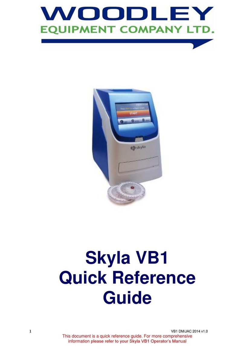
Woodley InSight V-IA User manual

Veterinary Immunoassay Analyser
Service Manual


Contents
I Product Introduction...................................................................................................................... 4
I.1 Analyser Structure............................................................................................................... 4
I.2 Intended Use ....................................................................................................................... 4
I.3 Technical Specifications ...................................................................................................... 4
I.4 Analyser System.................................................................................................................. 5
I.5 Analyser Detection Principle ............................................................................................... 5
II Contents......................................................................................................................................... 7
III Installation....................................................................................................................................... 7
III.2 Instructions ........................................................................................................................ 7
III.3 Operation Procedures ....................................................................................................... 8
III.4 Warnings............................................................................................................................ 8
IV Software Introduction ..................................................................................................................... 9
V Quality Control............................................................................................................................... 9
VI Further Product Information ......................................................................................................... 9
VII Maintenance and Care ................................................................................................................ 9
VII.1 Daily Maintenance and Care................................................................................................ 9
VII.2 Analyser Component Instruction .......................................................................................... 9
VII.3 Troubleshooting – Common Faults and Solutions ............................................................. 22
VII.4 Error Codes ........................................................................................................................ 23
VII.5 Troubleshooting and Repairing .......................................................................................... 27
VII.6 Settings .......................................................................................................................... 30
VII.7 V-IA Software upgrade........................................................................................................ 33
VII.8 V-IA Linux systems upgrade............................................................................................... 33
VIII Interpretation of Medical Device Label..................................................................................... 36
VIX Transportation Conditions........................................................................................................ 37
VIX.1 Transportation ................................................................................................................... 37

4
I Product Introduction
I.1 Analyser Structure
I.2 Intended Use
InSight V-IA Veterinary Immunoassay Analyser uses Immunofluorescence technology
to provide accurate, quantitative laboratory results.
For in vitro diagnostic use only.
For veterinary use only.
InSight V-IA Veterinary Immunoassay Analyser is suitable for use in veterinary
laboratories.
I.3 Technical Specifications
I.3.1 Main Parameters
◆LED or Diode laser
◆Outputs: 1. USB interface (4)
2. Ethernet interface (1)
3. Double serial port
3.1 Serial Port 1: Automatic LIS uploading
3.2 Serial Port 2: PC adjustment
◆Display: 24-bit true colour LCD screen
◆Specimen Type: Whole blood, serum and plasma
◆Power Supply: Host Input DC: 24V 2.5A
Adaptor Input: 100-240VAC; 50/60Hz
◆Standard curve
Storage Method: ID card with 4K memory
◆Dimensions: 213 (W) x 303 (D) x 210 (H) mm
◆Weight: 4kg
◆Operating Temperature: 10-30°C
◆Relative Humidity: ≤ 70%

5
I.3.2 Performance Specifications
◆Repeatability: CV≤10%
◆Stability: σ≤±8%
◆Linear Correlation: r≥0.97
◆Accuracy: Δn≤±15%
I.4 Analyser System
◆Hardware Core: ARM Cortex™ A8/A7
◆Software: Linux
◆Excitation Light: 470nm
◆Fluorescence Light: 525nm
I.5 Analyser Detection Principle
1.5.1 Cartridge information
You must only use the cartridge provided by Woodley Equipment Company.
◆There is a barcode on the cartridge. It shows the Lot Number of the cartridge. The
analyser will read the barcode to recognise which items and which Lot is being tested.
Lot No. Name Rule:
Long Lot Number: H0ABYYMMXX
Short Lot Number: ABXX
Code
Meaning
Sample: H053210113
Example Sample Meaning
H0
Fluorescent products
H0
Fluorescent products
AB
items type
32
T4
YYMM
Produce time
2101
Produce in January,2021
XX
Lot
13
Number of Lot
◆The arrow shows the direction the cartridge is inserted into the analyser.
◆Sample port is where the sample is applied.
◆The detection window is the area of the analyser reading the fluorescent signal.
◆C Line - It is a fluorescent control line and it is a control line for the analyser to check
if the cartridge is valid. The C line cannot be seen by eye.
◆T Line - It is a fluorescent test line. The analyser will read the fluorescent signal and
ID chip information to give the result. The T line cannot be seen by eye.
◆Blue Line - At the end of the detection window. When the sample is added to the
cartridge correctly, the blue line will disappear after the sample flows over the
detection window.

6
Caution: If the blue line is still shown after analysis, please check if the operation is
correct or the cartridge is valid.
1.5.2 ID chip
All the information of the test cartridge is saved in the ID chip. Every Lot of tests has a
unique ID chip.
You can read the ID chip information on the Item page.
1.5.3 Test principle
1. Sample is added and flows through the fluorescent antibody that is labelled on the
detection window.
2. Laser light source excites fluorescence.
3. The emitted light is collected and converted into electrical signals.
4. The concentration of the analyte is calculated from the electrical signal and
information from the ID chip.

7
II Contents
No.
Accessories
Quantity
Remark
1
Power Adaptor
1
Included
2
Instructions for Use
1
Included
3
Ethernet Cable
1
Included
III Installation
III.1 Installation
III.1.1 Unpacking and checking
1. Gently remove the analyser and accessories from the packaging box. Save the
packaging materials for future transport or storage of the analyser. Check the
accessories against the packing list.
2. Check the analyser and accessories to see if they are in good condition.
Notice: If there are any problems, please contact Woodley Equipment Company.
III.1.2 Analyser placement
1) The analyser should be placed in a clean and ventilated room with temperature
between 10°C ~ 30°C, relative humidity of less than 70%, away from direct sunlight.
2) Make sure the vents are not obstructed and that there is at least 5cm of clearance
around the analyser.
3) Connect the power adapter to the power interface of the analyser and turn on the
power.
4) Do not place any items on top of the analyser.
III.2 Instructions
Please note that the operating temperature of test reagents is based on each cartridge’s
instructions. Perform tests in strict accordance with the cartridge operating instructions
provided in each cartridge.

8
III.3 Operation Procedures
III.3.1 Preparation
1) When switched on, the analyser will run a self-test and the cartridge holder retracts
as shown below.
2) The software will start automatically and display the main home screen.
3) For the use and storage of reagents, please refer to the cartridge operating
instructions.
4) Insert ID code chip for the test to be analysed. Select “Read ID Card”.
5) Enter patient details in the ‘detail’ section.
6) Select standard test or instant test (refer to Section IV.2).
7) Place the test cartridge with specimen (follow cartridge operating instructions) onto
the cartridge holder and run prepared test.
Notice:
⚫Do not touch the cartridge holder when it’s moving.
⚫Do not interfere with the software during testing.
III.3.2 After analysis
1) The test cartridge will be released from the analyser once the test is complete.
2) The cartridge holder will reset.
3) Used test cartridges and pipette tips should be disposed as medical waste in
accordance with local regulations.
III.4 Warnings
The sign denotes notifications and errors.
2. Cartridge holder
1. Cartridge

9
IV Software Introduction
V Quality Control
VI Further Product Information
(See user manual)
VII Maintenance and Care
VII.1 Daily Maintenance and Care
VII.1.1 Maintenance
◆The users must check the analyser and accessories regularly.
◆Ensure the power outlet is connected correctly.
◆Check if the power cord is damaged or broken by visual inspection. If the power
cord is faulty, please replace.
◆Before cleaning the analyser, turn off the power and disconnect the power cord.
◆When cleaning the analyser, wipe using a damp, lint free cloth. The following
solutions can be used for cleaning: alcohol or mild detergent.
Notices:
Please do not use gasoline, diluent or other organic solvents to clean the analyser.
VII.2 Analyser Component Instruction
Please follow the assembly process as below.
Tools:
◆Screw driver
◆Knife
◆Heat gun
◆Tweezers

10
VII.3 Analyser Assembly
Prefix
Number
Name
Specific
Quantity
AA
1
Top cover assembly
Assembly
1
AA
2
Front cover assembly
Assembly
1
AA
3
Bottom cover assembly
Assembly
1
AA
4
Bottom cover screw(see
Figure:7.2.1.1)
PB3*8
(ST2.9*8)
6
Disassembly of Analyser
◆Disassemble 6 Bottom cover screens (Prefix Number: AA-4) on bottom side.
Figure 7.2.1.1
1
2
3

11
◆Separate the cover as shown in Figure 7.2.1.1.
◆Take off the cartridge holder.
◆Take off the top cover assembly carefully as shown in Figure 7.2.1.1.
Figure 7.2.1.2
◆Pull out the screen cable.
◆Disassemble 5 screws as shown in Figure 7.2.1.2.
◆Separate the front cover and top cover as shown in Figure 7.2.1.3.
Figure 7.2.1.3
Caution:
Hold the body of connector when pulling out, do not hold the wire. The red wire should
point towards the white arrow/point mark when re-assembling. (See Figure 7.2.1.4)

12
Figure 7.2.1.4
Top Cover Assembly
Prefix
Number
Name
Specific
Quantity
TC
1
Top cover
Top cover-Woodley
1
TC
2
Printer assembly
Assembly
1
TC
3
printer cover plate
Printer cover plate-prey
1
TC
4
Printer screw (see Figure 7.2.2.1)
M3*6
4
Disassembly of Top Cover
◆Disassemble the 4 printer screws (TC-4).
◆Separate the printer and top cover as shown in Figure 7.2.2.1.
Notice: Take off the printer cover on the back side of the top cover before taking out
the printer.
2
1
3

13
Figure 7.2.2.1
Front Cover Assembly
Prefix
Number
Name
Specific
Quantity
FC
1
Front cover
Front cover-Woodley
1
FC
2
Screen cover
Screen cover-Woodley
1
FC
3
Screen assembly
AT070TN92+ MT-1374
1
FC
4
Screen screw (see Figure:7.2.3.1)
PB3*8(ST2.9*8)
5
Figure:7.2.3.1
2
1
3

14
Disassembly of Front Cover
◆Disassemble 4 screen screws (FC-4). See Figure 7.2.3.1.
◆Open the Adhesive tape between board and screen using a knife. See Figure 7.2.3.2.
A heat gun can help you disassemble the tape easier.
◆Pull out the FPC from connector.
Caution: Please be careful, do not cut the FPC while cutting the tape by knife.
Figure 7.2.3.2
Bottom Cover Assembly
Prefix
Number
Name
Specific
Quantity
BC
1
Bottom cover
Bottom cover-Woodley
1
BC
2
Door
Assembly
1
BC
3
Detection assembly
Assembly
1
4
2
3
5
6
1
9

15
BC
4
Main board assembly
Assembly
1
BC
5
Power Switch
MR-2-210-C5N-
BBblack 15mm*21mm
1
BC
6
ID chip reader
Assembly
1
BC
7
Screw (See figure 7.2.4.2)
PB3*8 (ST2.9*8)
5
BC
8
Screw (See figure 7.2.4.1)
PB3*8 (ST2.9*8)
2
BC
9
Barcode Reader
Scanner
1
Disassembly of Bottom Cover
◆Loosen the two screws (BC-10), pull out the connector and take the ID chip reader
(BC-6) out. See Figure 7.2.4.1.
◆Loosen the 5 screws (BC-7), pull out the connector and take the detection assembly
out. See Figure 7.2.4.2.
Figure:7.2.4.1
Figure 7.2.4.2

16
Detection Assembly
Prefix
Number
Name
Specific
Qty
DA
1
Mounting base
Q235A
1
DA
2
Mounting plate of driven wheel
Q235A
1
DA
3
Kicker
Q235A
1
DA
4
Cartridge detection board plate
Q235A
1
DA
5
Motor mounting plate
Q235A
1
DA
6
guide rod mounting base
nylon
2
DA
7
optical reader mounting base
AL6063
1
DA
8
cartridge sliding plate
SUS304
1
DA
9
back limited switch
OMRON-SS-5GL2
1
DA
10
guide rod
CPSFJ6-265
2

17
DA
11
optical reader
assembly
1
DA
12
washer
M4
1
DA
13
shoulder screw
SMSB5-10-M4
1
DA
14
Flange bearing
5mm*18mm*5mm
2
DA
15
cartridge detection board
assembly
1
DA
16
stepping motor
42HSC1409-22B-200
1
DA
17
front limited switch
assembly
1
DA
18
timing pulley
HTPA20S2M060-K-P5
1
DA
19
set screws
M3*4
2
DA
20
belt
HTBN520S2M-60
1
DA
21
slider
nylon
1
DA
22
belt guider
SUS304 T=1
1
DA
23
slider plate
SUS430
1
DA
24
cartridge
PA6+15%glassfiber
1
DA
25
plate
SUS304
2
DA
26
spring
0.3*6*5-3
4
DA
27
screw
M3*6
20
DA
28
screw
M3*8
2
DA
29
screw
M3*12
2
DA
30
screw
M3*4
5
DA
31
screw
M2*10
2
DA
32
screw
M3*5
2
DA
33
screw
M3*6
4
DA
34
screw
M3*22
2
DA
35
screw
ST2.9*8
5
Detection Assembly Important Parts Function Instruction
No.
Name
Function
DA-3
Kicker
Removes the cartridge from the cartridge holder. The cartridge will be
dispensed out from the side door.
DA-9
Back limited
switch
Sensor that analyser will know the cartridge holder moves to the end
of the guide rod.
DA-11
optical reader
The key part of detection. Caution: It is a laser light source. Emit and
read the fluorescence signal of test kit. Do not open or remove it.
DA-15
Cartridge
detection board
Analyser will detect if the cartridge has been put in the cartridge
holder. If it is damaged, analyser will display “please insert card”
even if cartridge is on cartridge holder.
DA-17
front limited
switch
Sensor that analyser will know the cartridge holder moves to the front
of the guide rod.
--
Scanner
Read the barcode (Lot No) on the cartridge.

18
Figure 7.2.5.1
Caution: Detection assembly is a key part and precision assembly is important, the distance
between the parts are sensitive to detection and optical signal. The test result would be
affected by incorrect re-assembly.
Disassemble the Detection Assembly
◆Back limited switch: Take off 2 screws (DA-31), take out the back limited switch (DA-
9) after pulling out of the connector. See Figure 7.2.5.2.
Figure 7.2.5.2
◆Front limited switch: Take off 2 screws(DA-30)on the back side of detection assay,
take the Front limited switch(DA-17)after pulling out of the connector. See Figure
7.2.5.3.
Figure 7.2.5.3

19
◆Cartridge detection board: Take off the screw (DA-27) on cartridge detection board
(DA-15) after pulling it out of the connector. See Figure 7.2.5.4.
◆Scanner: Take off the screws on mounting base after pulling out of the connector. See
figure 7.2.5.5.
Figure 7.2.5.4 Figure 7.2.5.5

20
Wiring Diagram
1
2
3
4
5
6
8
7
9
10
11
12
13
Other manuals for InSight V-IA
1
Table of contents
Other Woodley Measuring Instrument manuals

Woodley
Woodley InSight V-CHEM User manual

Woodley
Woodley InSight V-IA PLUS User manual

Woodley
Woodley InSight V5 User manual

Woodley
Woodley Insight User manual

Woodley
Woodley Skyla VB1 User manual

Woodley
Woodley InSight V3 PLUS User manual

Woodley
Woodley Insight User manual

Woodley
Woodley The Edge User manual

Woodley
Woodley InSight Mini Chem User manual