woodmizer MP180 E6S User manual


Wood-Mizer®
Safety, Setup, Operation
and Maintenance
MP180 E6S rev. A1.01
MP180 E7S-V rev. A1.01
Safety is our #1 concern! Read and understand
all safety information and instructions before oper-
ating, setting up or maintaining this machine.
Form #2406
!
Original Instructions
Please keep for future reference

4 SW-07doc052521 Table of Contents
Table of Contest Section-Page
SECTION 1 INTRODUCTION 1-1
1.1 Machine Description ..............................................................................1-2
1.2 Planer/moulder major components ........................................................1-6
SECTION 2 SAFETY 2-1
2.1 Safety Symbols.......................................................................................2-1
2.2 Safety Instructions..................................................................................2-1
SECTION 3 SETUP & OPERATION 3-1
3.1 Multi-Planer Setup..................................................................................3-1
3.2 MP180 Multi-Planer Operation..............................................................3-5
SECTION 4 MAINTENANCE 4-1
4.1 Wear life .................................................................................................4-1
4.2 Sawdust Removal ...................................................................................4-1
4.3 Miscellaneous Maintenance ...................................................................4-1
4.4 Drive Belt Tension Adjustment..............................................................4-2
4.5 Long-Term Storage ................................................................................4-5
4.6 Safety Devices Inspection ......................................................................4-6
SECTION 5 MULTI-PLANER SPECIFICATIONS 5-1
5.1 Overall Dimensions ................................................................................5-1
5.2 Multi-Planer Specifications....................................................................5-2

INTRODUCTION
INTRODUCTION doc052521 1-1
1
SECTION 1 INTRODUCTION
Congratulations on your purchase of a Wood-Mizer Multi-Planer!
Wood-Mizer is committed to providing you with the latest technology, best quality, and strongest
customer service available on the market today. We continually evaluate our customers’ needs to ensure
we are meeting current wood-processing demands. Your comments and suggestions are welcome.
This documentation includes information on preparing the Multi-Planer for operation, servicing and
repairing the machine.
GENERAL
Check your Multi-Planer as soon as you receive it. Report any transport damage to the transport
company immediately.
Lift the Multi-Planer using a forklift or a pallet jack with lifting capacity of at least 500kg.
When replacing the spare parts, use only original parts and note that all electrical components must be
assembled by a qualified electrician.
APPLICATIONS
The Multi-Planer can be used for planing/moulding/thicknessing wood, chipboards, boards, etc..
Hard materials such as chipboards, teak, MDF, etc. require hard carbide tools.
It is not allowed to plan plastics, aluminium or other hard materials.
The Multi-Planer is designed for indoor use, with temporary outdoor use during good weather.
REQUIREMENTS
The Multi-Planer can be used in rooms with a temperature ranging from -15oC to +40 C. The ventilation
must be mechanical and in accordance with standards.
The Multi-Planer must be connected to a dust extractor. The dust extractor must be turned on when the
machine is working.
SAFETY DISTANCE
WARNING! No one, except the operator, should be within 3 meters of
The Multi-Planer's sides or 8 meters from the infeed and outfeed sides
during operation. Mark a limit to prevent anyone from accidentally
entering the risk area.

INTRODUCTION
Machine Description
1
1-2 doc052521 INTRODUCTION
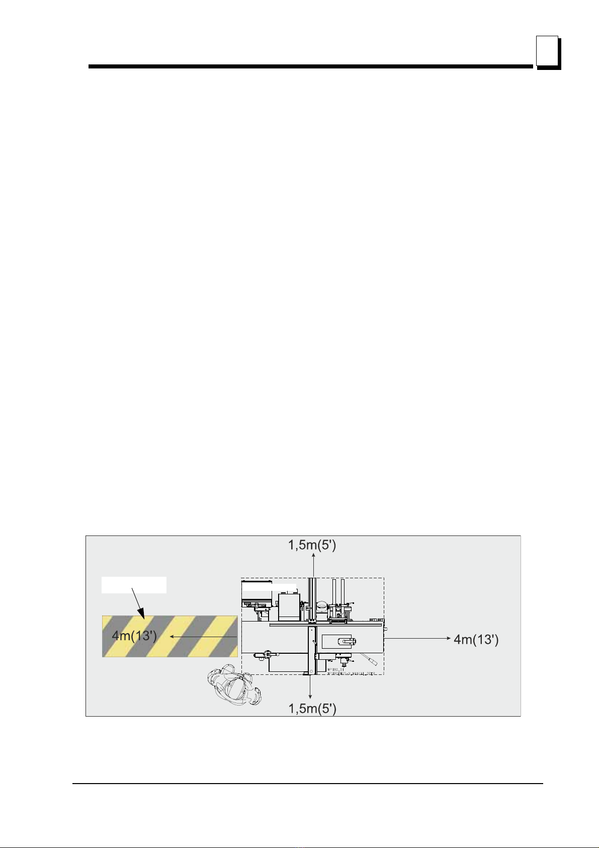
TIPS: An extended infeed table is practical to use, and prevents anyone from coming into the risk
area.
STORAGE
The machine must be placed in a dry area, as it is not fully protected against corrosion. If the machine
is placed in a cold area for an extended period of time, its unprotected components, such as tables or
cutters, must be lubricated with a large amount of e.g. paraffin. It is also a good idea to cover the device
for additional protection against corrosion. If the machine is supposed to be placed outdoors, its
unprotected components must be covered and lubricated with anti-corrosive agents.
1.1 Machine Description
The Wood-Mizer Multi-Planer is designed for straight and profiled planing of wooden elements used
for production of wooden houses and other construction elements used in the building industry and
garden programs. Other applications of the planer are forbidden.
The MP180 is a planer/moulder/thicknesser that can process two sides of a workpiece in a single pass.
The machine is contained in a stable and strong chassis. The Multi-Planer table is made of planed cast
iron.
The workpiece is fed, lying on the planer table, through the planer by feed rollers as well as an outfeed
roller. The rollers are driven by a chain transmission with separate motor. The workpiece is controlled
laterally with adjustable fences and pressure rollers.
The work is done using a top cutter and side cutter which are fixed to the planer table. All the cutters are
driven by separate motors, via a belt transmission.
The cutters and feed rollers are covered with a protective cover plate. The cover plate is supplied with a
safety switch. A 100 mm (4”) dia. hose is connected to the cutter.
TABLE SURFACE
The table is made of the highest quality cast. The table surface is specially processed for the highest
precision and the best anti-friction qualities.
When the Multi-Planer is new, it requires a breaking-in period until the table gets a slightly shinier surface
to optimize the anti-friction qualities. It is recommended that lubricant or wax be applied to the table
during this period.
Using the machine correctly, you will obtain a perfectly smooth surface and a high degree of accuracy.
The Multi-Planer should be operated only by an adult who has read and understood the entire operator’s
manual.
The Multi-Planer is built to be durable and easy to operate and maintain.

INTRODUCTION
Machine Description
INTRODUCTION doc052521 1-3
1
MACHINE AND SITE PREPARATION
The machine is delivered on a pallet. Due to the weight, it has to be transported with auxiliary carrier
equipment and in accordance with the general safety rules.
Check your Multi-Planer as soon as you receive it. Any transport damage must be reported to the
transport company immediately.
Most of the machine is protected against rust, but it will require extra maintenance in the form of
lubrication for all the parts that are not protected against rust. See the Maintenance section.
Place the planer on a stable and flat base.
It is recommended that the Multi-Planer be bolted to the ground, if it does not have to be
moved.
Ensure that there is enough space for the longest boards you want to plane on the infeed and
outfeed sides, and that there is enough space for maintenance and timber stocks.
Connect the dust hoses and fix them using the hose clips on the planer and fan.
Hang the electrical cable of the machine to the ceiling or protect it in another way. Never step
on the cable. The Multi-Planer should be connected via an earth-fault protection switch.
CAUTION! The illuminance at the operator's position should be at least 300lx. The light source
cannot cause the stroboscopic effect. Ensure that there is no risk of glare.
SPACE REQUIREMENTS
The Multi-Planer needs a space of at least 4 m (13’) wide.
The required length depends on the length of workpieces you want to plane. The minimum length is 4 m
(13’) from the front and from the end of the machine.
Control panel
Higher risk area
Safety distance for all other persons

INTRODUCTION
Machine Description
1
1-4 doc052521 INTRODUCTION
ANCHORING
For the highest safety, the Multi-Planer must be anchored to the floor with 8-10 mm diameter anchor
bolts.
TOOLS REQUIRED TO USE THE MULTI-PLANER:
Allen wrench 4 mm (supplied)
Allen wrench 5 mm
Allen wrench 6 mm
Flat wrench 10 mm (supplied)
Wrench 10 mm
Box wrench 13 mm
Flat wrench 30 mm (supplied, for cutter)
Adjustable wrench 8” or 10” (cutter)
Slide caliper
Measuring tape or ruler
Paraffin oil for grindstone
SPACER RINGS THAT ARE SUPPLIED:
3 x 40 mm height (per cutter)
2 x 20 mm height (per cutter)
2 x 10 mm height (per cutter)
1 x 5 mm height (per cutter)
1 x 2 mm height (per cutter)
1 x 1 mm height (per cutter)
1 x 0.5 mm height (per cutter)
1 x 0.3 mm height (per cutter)
1 x 0.2 mm height (per cutter)

INTRODUCTION
Machine Description
INTRODUCTION doc052521 1-5
1
1 x 0.1 mm height (per cutter)
These spacer rings are necessary to set the required height.
CHIP EXTRACTOR
The MP180 Multi-Planer must be connected to a chip extractor with a total capacity of at least
2 000m3/h. Remember that the chip container has to be equipped with an air vent (e.g. a fine net or filter
if dust is collected indoors). Poor suction is often caused by poor airflow from the chip container. During
work in heated rooms, it is necessary to remember that the fan will quickly cool the space if the filtered
air is not supplied back into the building. The fire risk and dust emissions (discharge) must be considered
because of chip collection.
WARNING! There is a risk of fire and dust emission because of chip
collection.
Contact the local authorities for advice about designing the chip collection system to conform to the
national rules.
It is necessary to set the fan so that it is easy to reach the switch.
IMPORTANT! Remove the chips from the Multi-Planer when the work
is finished.
TECHNICAL REQUIREMENTS FOR THE CHIP EXTRACTOR1
The chip extractor must be approved according to the CE standard.
The chip extractor hose diameters for the Multi-Planer = 100 mm (4”) x 2.
The pressure drop in the Multi-Planer is 20 mm column of water at 25 m/s.
The dust extractor airflow (“without external connection”) should be 2000 m3/h.
IMPORTANT! The dust extractor hoses must be grounded or made of
materials that do not accumulate an electrostatic charge.
CAUTION! Always turn on the chip extractor before starting the
machine.
1. EN 12779:2016-04 standard contains requirements for chip and dust extraction systems equipment with
fixed installations.
!
!

INTRODUCTION
Planer/moulder major components
1
1-6 doc052521 INTRODUCTION
1.2 Planer/moulder major components
FIG. 1-1 MP180
Cutter with
Safety Cover
Electric box with
control panel Chip Duct
Bottom Table Height
Adjustment Crank
Table Height
Scale
Emergency Switch
Lockable Castors
(optional)
Fence
Top Table Height
Adjustment Handle
Top Table Height
Scale
Handle for pushing
material
Feed Rollers Drive
Motor
Feed Rollers Drive
Motor

Safety
Safety Symbols
Safety EGdoc052521 2-1
2
SECTION 2 SAFETY
2.1 Safety Symbols
The following symbols and signal words call your attention to instructions concerning your personal
safety. Be sure to observe and follow these instructions.
DANGER! indicates an imminently hazardous situation which, if not
avoided, will result in death or serious injury.
WARNING suggests a potentially hazardous situation which, if not
avoided, could result in death or serious injury.
CAUTION! refers to potentially hazardous situations which, if not
avoided, may result in minor or moderate injury or damage to
equipment.
IMPORTANT! indicates vital information.
NOTE: gives helpful information.
Warning stripes are placed on areas where a single decal would be
insufficient. To avoid serious injury, keep out of the path of any
equipment marked with warning stripes.
2.2 Safety Instructions
NOTE: ONLY safety instructions regarding personal injury are listed in
this section. Caution statements regarding machine damage appear
where applicable throughout the manual.
Observe safety instructions.
IMPORTANT! Read the entire Operator's Manual before operating the
Multi-Planer. Take notice of all safety warnings throughout this manual
and those posted on the equipment. Keep this manual with this
equipment at all times, regardless of ownership.
Read all additional manufacturer’s manuals and observe any
applicable safety instructions including dangers, warnings, and
cautions!
!
!

Safety
Safety Instructions
2
2-2 EGdoc052521 Safety
IMPORTANT! Only adult persons who have read and understood the
entire operator's manual should operate the Multi-Planer. The machine
is not intended for use by or around children. Never operate the
Multi-Planer under the influence of alcohol or drugs.
IMPORTANT! The operator of the Multi-Planer should get adequate
training in the operation and adjustment of the machine.
IMPORTANT! It is always the owner's responsibility to comply with all
applicable federal, state and local laws, rules and regulations
regarding the ownership and operation of your Wood-Mizer
Multi-Planer. All Wood-Mizer Multi-Planer owners are encouraged to
become thoroughly familiar with these applicable laws and comply with
them fully while using the machine.
Wear safety clothing.
WARNING! Secure all loose clothing and jewelry before operating this
machine. Failure to do so may result in serious injury or death.
WARNING! Always wear safety goggles and gloves when operating
the machine. Failure to do so may result in serious injury.
WARNING! Always wear ear, respiration and foot protection when
operating the Multi-Planer.

Safety
Safety Instructions
Safety EGdoc052521 2-3
2
Keep the machine and area around clean.
DANGER! Maintain a clean and clear path for all necessary movement
around the Multi-Planer and lumber stacking areas. Failure to do so
will result in serious injury.
Dispose of sawing by-products properly.
IMPORTANT! Always properly dispose of all sawing by-products,
including sawdust and other debris.
Check the Multi-Planer before operation.
DANGER! Make sure all guards and covers are in place and secured
before operating the Multi-Planer. Check that all knobs, screws, nuts,
fences, sleeves, planing cutters, planing knives, etc. are properly
tightened. Also check that the cutter can rotate freely and that there are
no tools in or on the machine before it is started. Failure to do so may
result in serious injury.
WARNING! Always shut off the motor to stop the cutter whenever the
Multi-Planer is not in use. Failure to do so may result in serious injury.
WARNING! Do not for any reason adjust the motor drive belts with the
motor running. Failure to do so will result in serious injury.
Keep all people away.
DANGER! No one, except the operator, should be within 3 meters of
the Multi-Planer sides during operation. Failure to do so will result in
serious injury.
Keep hands away.
DANGER! Moving parts can cut or crush fingers or hand. Keep hands
clear. Make sure all guards and covers are in place and secured before
operating the Multi-Planer. Failure to do so may result in serious injury.
DANGER! Always be aware of and take proper protective measures
against rotating shafts, pulleys, fans, etc. Always stay a safe distance
from rotating members and make sure that loose clothing or long hair
!

Safety
Multi-Planer Operation
2
2-4 EGdoc052521 Safety
do not engage rotating members resulting in possible injury.
WARNING! Beware of rotating parts. Shut down the machine and
allow all moving parts to come to a complete stop before removing any
guards and covers. Do NOT operate the Multi-Planer with any guards
or covers removed.
DANGER! Before changing the knives or performing any service to the
machine, disconnect the power cord from the electric box.
IMPORTANT! The knife and feed assembly covers are equipped with
limit switches. After opening the cover, the motor will turn off and all
moving parts will stop. The limit switches should always be in proper
working condition.
Multi-Planer Operation
CAUTION! The workplace should always be well illuminated.
The illuminance at the operator's position should be at least 300lx.
Never use the Multi-Planer under the influence of strong medication,
alcohol or drugs.
WARNING! Make sure the knives are properly fastened before starting
the motor.
WARNING! Never place tools or hands in the infeed or outfeed areas
when the Multi-Planer is running.
IMPORTANT! When starting the machine for the first time, check that
the main motor rotation direction is as indicated by the arrow located
on the motor body (fan guard). If the rotation direction is incorrect,
invert the phases in the phase inverter in the power socket (electrical
box). Setting the phases in the phase inverter correctly will ensure
correct rotation directions of all motors.
DANGER! Always measure the workpiece and set suitable thickness
and width before planing. There is a risk of accident if you feed in a
workpiece that is not high enough for the feed rollers to get hold of it.
When planing smaller material, it should be stiffened/extended, e.g.
with a longer piece of wood.
!

Safety
Multi-Planer Operation
Safety EGdoc052521 2-5
2
Never stand in front of the material being fed or received, because it
may kickback suddenly towards the operator. This applies to both the
infeed and outfeed sides, although the risk is higher on the infeed side.
DANGER! Planing/moulding is possible only in the direction shown
below. The arrow “A” indicates the planing direction on the upper table.
The arrow “B” indicates the planing direction on the lower table. Never
try to perform planing/moulding in the opposite direction!
DANGER! When planing on the upper table, use the pusher “C”
provided with the machine. It is not allowed to push the material by
hand!
Use proper maintenance procedures.
DANGER! Make sure all electrical installation, service and/or
maintenance work is performed by a qualified electrician and in
accordance with applicable electrical codes.
DANGER! Hazardous voltage inside the electric boxes and at the
motor can cause shock, burns, or death. Disconnect and lock out
power supply before servicing! Keep all electrical component covers
closed and securely fastened during machine operation.
FIG. 2-1

Safety
Multi-Planer Operation
2
2-6 EGdoc052521 Safety
WARNING! Consider all electrical circuits energized and dangerous.
WARNING! Never assume or take the word of another person that the
power is off; check it out and lock it out.
WARNING! Do not wear rings, watches, or other jewelry while working
around an open electrical circuit.
IMPORTANT! The Multi-Planer is equipped with an emergency stop
button. It is used to immediately stop the motor in case of emergency.
The emergency stop button should always be in good condition.
IMPORTANT! The Multi-Planer should not be modified by the owner.
Use only original spare parts.
Keep safety labels in good condition.
IMPORTANT! Always be sure that all safety decals are clean and
readable. Replace all damaged safety decals to prevent personal
injury or damage to the equipment. Contact your local distributor or
Wood-Mizer Customer Service to order more decals.
IMPORTANT! If replacing a component which has a safety decal
affixed to it, make sure the new component also has the safety decal
affixed in the same place.
Fire protection
CAUTION! The work-stand of the Multi-Planer should be equipped
with a 4 kg or bigger dry powder extinguisher.
!
!

Safety
Safety Labels Description
Safety EGdoc052521 2-7
2
Safety Labels Description
See the table below for safety labels description.
TABLE 2-0
Label View Label Number Description
096317 CAUTION! Carefully read the operator’s
manual before operating the machine.
Observe all instructions and safety rules
when operating.
099220 Close all guards and covers prior to
operating the machine.
099221H CAUTION! Keep safe distance when the
machine is working.
099220
099221h

Safety
Safety Labels Description
2
2-8 EGdoc052521 Safety
096316 Do not open or close the electric box when
the switch is not in the ”0” position.
096319 Always disconnect the power cord before
opening the electric box.
S12004G Always wear safety goggles when
operating the Multi-Planer!
S12005G Always wear protective ear muffs when
operating the Multi-Planer!
TABLE 2-0

Safety
Safety Labels Description
Safety EGdoc052521 2-9
2
501465 Always wear safety boots when operating
the Multi-Planer!
510080 Always wear safety gloves when operating
the Multi-Planer!
S20097 Motor rotation direction
P85070 CE safety certification510080
535252 Use the continuously variable transmission
only when the feed is turned on.
TABLE 2-0
S20097

Safety
Safety Labels Description
2
2-10 EGdoc052521 Safety
551139 Warning! The side cutter rotates for 10
seconds after the machine is shut-off.
536401 Cutter rotation direction
TABLE 2-0
10
sec
551139
This manual suits for next models
1
Table of contents
Other woodmizer Planer manuals