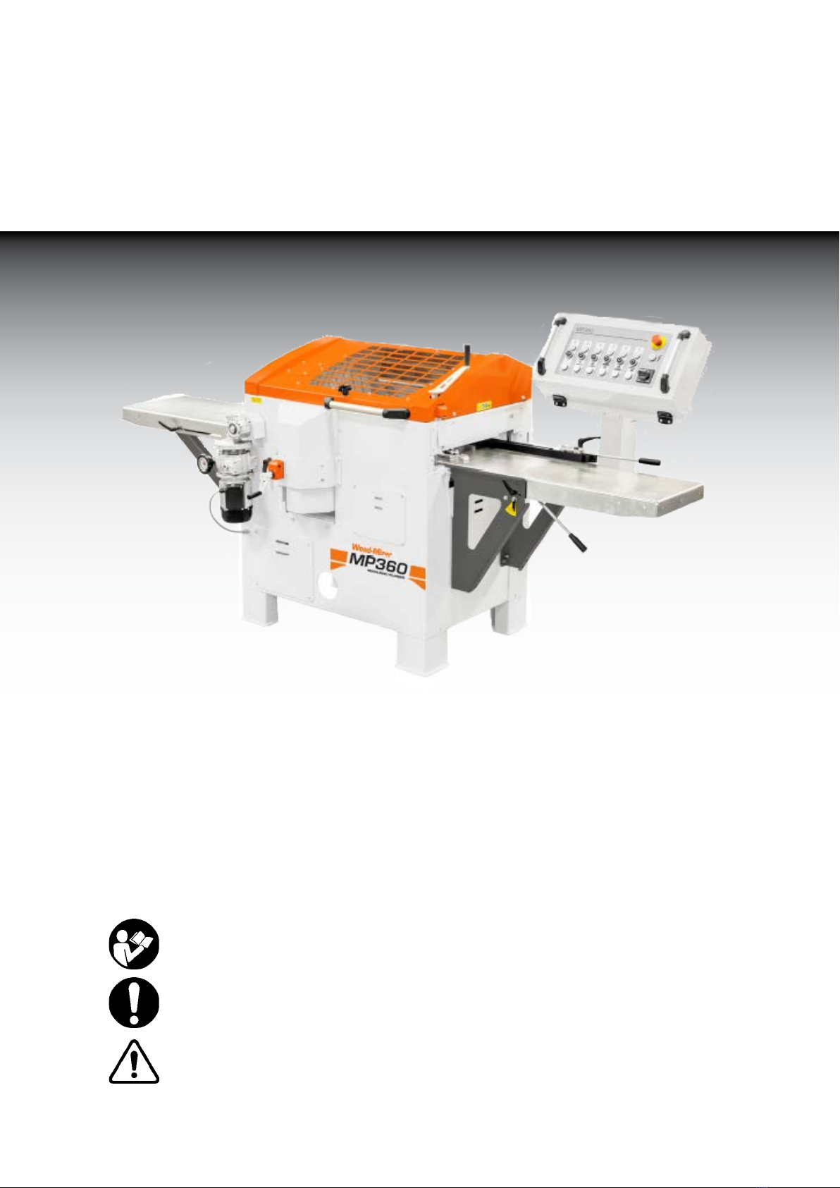
woodmizer MP360 User manual

MP360 Planer Moulder
USER MANUAL
Wood-Mizer
Read through the user manual carefully and make sure you understand its
contents before you use the planer/moulder.
This user manual contains important safety instructions.
WARNING! Incorrect use can result in serious personal injury or even death to
the operator or others.

©2018
Printed in the United States of America. All rights reserved. No part of this manual may be
reproduced in any form by any photographic, electronic, mechanical or other means or
used in any information storage and retrieval system without written permission from
Wood-Mizer
8180 West 10th Street
Indianapolis, Indiana 46214

Table of contents
Safety instructions 6
Tools required 8
Machine description 8
Preparations 9
Setup 10
Chip management 10
In and outfeed table 11
Starting the planer 11
Control panel 12
Bottom cutter 13
Top cutter 15
Molding knife in bottom and
top cutter 17
Side cutters 18
Variable Feed Motor 22
Maintenance 23
Setting the upper chassis' plan 24
Planing tips 24
MP360 Profile knives 25
Electrical schematic 28
Technical data 31
List of components 32
Overview Images 34
Getting started 2
Warranty 3
Wood-Mizer
®
from forest to final form

Wood-Mizer is committed to providing you with the latest technology, best quality,and
strongest customer service available on the market today. We continually evaluate our
customers’ needs to ensure we are meeting current wood-processing demands. Your
comments and suggestions are welcome.
General Contact Information
Toll free phone numbers are listed below for the continental U.S.
and Canada. See the next page for contact information for more
Wood-Mizer locations.
Office Hours: All times are Eastern Standard Time.
Please have your vehicle identification number and your customer number ready when you call.
Wood-Mizer will accept these methods of payment:
Visa, Mastercard, or Discover
COD
Prepayment
Net 15 (with approved credit)
Be aware that shipping and handling charges may apply. Handling charges are based on size
and quantity of order. In most cases, items will ship on the day they are ordered. Second Day
and Next Day shipping are available at additional cost.
If your equipment was purchased outside the United States or Canada, contact the distributor
for service.
United States Canada
Sales 1-800-553-0182
Service 1-800-525-8100
Website www.woodmizer.com
1-877-866-0667
1-877-866-0667
www.woodmizer.ca
E-mail [email protected] [email protected]om
Monday - Friday Saturday
(Indianapolis Office Only)
Sunday
8 a.m. to 5 p.m. 8 a.m. to 12 p.m. Closed
GETTING STARTED
Wood-Mizer
®
from forest to final form
Read this manual completely before starting!!
2

Wood-Mizer Locations
USA World Headquarters Canadian Headquarters
Serving North & South America, Oceania, East
Asia
Wood-Mizer LLC 8180
West 10th Street
Indianapolis, IN 46214
Phone: 317.271.1542 or 800.553.0182
Customer Service: 800.525.8100 Fax:
317.273.1011
Email: [email protected]
Serving Canada
Wood-Mizer Canada
396 County Road 36, Unit B
Lindsay, ON K9V 4R3
Phone: 705.878.5255 or 877.357.3373
Fax: 705.878.5355
Email:
Brazil Headquarters Europe Headquarters
Serving Brazil
Wood-Mizer do Brasil
Rua Dom Pedro 1, No: 205 Bairro: Sao Jose
Ivoti/RS CEP:93.900-000
Tel: +55 51 9894-6461/ +55 21 8030-3338/ +55
51 3563-4784
Email: [email protected]
Serving Europe, Africa, West Asia
Wood-Mizer Industries Sp z
o.o. Nagorna 114
62-600 Kolo, Poland
Phone: +48.63.26.26.000
Fax: +48.63.27.22.327
Branches & Authorized Sales Centers
For a complete list of dealers, visit www.woodmizer.com
WARRANTY
Wood-Mizer
®
LLC
Limited Product Warranty
Wood-Mizer LLC (“Warrantor”), an Indiana corporation with its principal place of business at 8180 West
Tenth Street, Indianapolis, IN 46214-2400 USA, warrants to the purchaser (“Purchaser”) that for the time
periods specifically stated herein and subject to the terms, conditions and limitations stated herein, the
equipment manufactured by the Warrantor will be free from defects in material and workmanship
attributable to Warrantor so long as, during the warranty periods stated herein, the equipment is installed,
operated and maintained in accordance with the instructions provided by Warrantor.
Wood-Mizer MP360
3

Wood-Mizer
®
from forest to final form
PRODUCT MODEL CLASS LENGTH OF WARRANTY EFFECTIVE DATE
USA&CANADA NON USA &
CANADA
Portable Sawmills,
Resaws, Edgers LT, LX, HR, EG Two years One year
Date of purchase
Portable Sawmills
with Chassis LT28, LT35, LT40,
LT50, LT70, LX450
Two years, excluding
the chassis, which
chassis shall have a five
year warranty One year
Industrial Sawmills,
Resaws, Edgers WM, HR, EG, TVS, SVS One year One year Date of purchase or
date of installation /
training (if applicable),
whichever occurs first,
not to exceed 6
months from date of
purchase
TITAN Industrial WB, TV, HR, EG, EA, MR One year One year
Material Handling TWC,IC, TD, LD,
GC, CR, CB, CC One year One year
Blade Maintenance BMS, BMT,BMST One year One year
Date of purchase
Options and Accessories Various One year* One year*
Moulders, Kilns MP, KS, KD One year One year
Pallet Dismantlers PD One year One year
Log Splitters FS One year One year
Replacement Parts Various 90 days 90 days
* Warranty on Options will match the warrantyon the primaryequipment when purchased on same invoice.
Exclusions from 90 Day, Limited One Year and Two Year Warranty
Warrantor shall have no responsibility under this warranty for any wear components, including, but not limited to: belts,
blade guides, blades, electric motor brushes, drum switches, filters, fuses, hoses, bearings (excluding cylindrical drive
bearings), bushings, cable carriers, and spark plugs. All wear components are furnished “as is”, without any warranty
from Warrantor. This limited warranty does not cover any defects caused by misuse, negligence, alterations, damage
due to overload, abnormal conditions, excessive operation, accident, or lack of performance of normal maintenance
services.
Several components which are used in the manufacture of the equipment but not manufactured by Warrantor such as
cant hooks, power plants, laser sights, batteries, tires, and trailer axles have warranties provided by the original
equipment manufacturer (written copies available upon request). Warrantor does not separately warrant such items.
Components or equipment manufactured by third parties are not covered by this warranty. Warrantor, however, will
provide reasonable assistance to the Purchaser to make claims againstany warranties applicable to such component
parts as provided by such original equipment manufacturers. Components or equipment manufactured by third parties
are not covered by this Warranty.
Five Year Limited Chassis Warranty
The limited five year chassis warranty described above, DOES NOT extend to (a) any damage stemming from
accident, improper towing, overload, abuse, misuse, abnormal conditions, negligence, excessive operation, or lack of
maintenance, (b) rust caused by exposure to corrosive atmospheric conditions, or (c) the sawmill head, carriage, axle,
brakes, or any hydraulic or electrical components attached to the chassis.
4

Wood-Mizer MP360
Warrantor’s Obligations as To Defects
In the event that the equipment failsto perform due to defective materials orworkmanship attributable to Warrantor
under normal use and service within the established warranty period, Purchaser’s sole and exclusive remedy and
Warrantor’s sole liability shall be to replace or repair, in Warrantor’s sole and subjective discretion, any defective part
at Warrantor’s principal place of business without cost to the Purchaser if such defect exists. The determination of
whether a product is defective shall be made by Warrantor in Warrantor’s sole and subjective discretion. The
Purchaser must notify Warrantor prior to shipping any defective part. Warrantor, at its sole discretion, may cover
expenses incurred in shipping the defective part to Warrantor for evaluation; provided, however, that Warrantor will not
be responsible for labor, travel time, mileage, removal, installation or incidental or consequential damages. However,
any part in excess of 140 pounds must be returned by the Purchaser, to the Warrantor’s nearest authorized facility at
the Purchaser’s expense, if return is requested by Warrantor. Warrantor shall have a reasonable time within which to
replace or repair the defective part. IfWarrantor determines that the product is not defective under the terms of this
warranty in Warrantor’s sole and subjective discretion, then Purchaser shall be responsible for any expenses incurred
by Warrantor in returning the equipment to the Purchaser.
Limitations and Disclaimers of Other Warranties
EXCEPT FOR THE EXPRESSWARRANTY PROVISIONS STATED ABOVE,WARRANTOR DISCLAIMS ALL
WARRANTIES, EXPRESS AND/OR IMPLIED, INCLUDINGWITHOUT LIMITATION, THE IMPLIED WARRANTIES
OF MERCHANTABILITY, AND FITNESS FOR A PARTICULAR PURPOSE, NONINFRINGEMENT AND TITLE. No
representation or other affirmation of fact by representatives of Warrantor, whether verbal or in writing, including
photographs, brochures, samples, models, or other sales aids, shall constitute a warranty or other basis for any legal
action against Warrantor. There are no other representations, promises, agreements, covenants, warranties,
guarantees, stipulations or conditions, express or implied, by Warrantor except as expressly set forth herein. THE
ORIGINAL PURCHASER AND ANY INTENDED USER OR BENEFICIARY OF THIS EQUIPMENT, SHALL NOT BE
ENTITLED TO RECOVER ANY INDIRECT, SPECIAL, PUNITIVE, EXEMPLARY, CONSEQUENTIAL, SPECIAL,
OR INCIDENTIAL DAMAGES OR LOSES, INCLUDING BUT NOT LIMITED TO, DAMAGES OF LOST
PRODUCTION, LOST REVENUE, LOST PRODUCT, LOST PROFITS, LOST BUSINESS, LOSS OF USE, LOSS
OF GOODWILL, OR BUSINESS INTERRUPTION, FROM WARRANTOR FOR ANY REASON WHATSOEVER
INCLUDING WITHOUT LIMITATION WARRANTY OR DEFECT IN THE PRODUCT REGARDLESS OF THE SOLE,
JOINT AND/OR CONCURRENT NEGLIGENCE, BREACH OF CONTRACT, BREACH OF WARRANTY, STRICT
LIABILITY IN TORT OR STATUTORY CLAIMS OR OTHER LEGAL FAULT OR RESPONSIBILITY OF EITHER
WARRANTOR OR PURCHASER OR ITS EMPLOYEES OR AGENTS. Warrantor does not warrant that its
equipment meets or complies with the requirements of any particular safety code or governmental requirements.
Defective items replaced underthe terms of this warranty become the property of Warrantor.
Design Changes
Warrantor reserves the right to change the design of its products from time to time without notice and without
obligation to make corresponding changes in or to its products previously manufactured.
Rights of Purchasers
The validity and effect of this limited warranty as well as its interpretation, operation and effect, shall be determined
exclusively by the principles of law and equity of the State of Indiana, USA. This limited warranty gives Purchaser
specific legal rights. Purchaser may also have other rights, which may vary from state to state. Some states may not
allow limitations as to the duration of implied warrantiesor to the exclusion or limitationof incidental or consequential
damages, so some of the limitations and exclusions detailed set forth above may not apply. In the event that any one
or moreof the provisions of this warranty shall be or becomeinvalid, illegal or unenforceablein any respect, the
validity, legality and enforceability of the remaining provisions of this warranty shall not be affected thereby.
Interpretations
ThisWarranty constitutes the entire warrantyagreement between Warrantor and Purchaser and supersedesany prior
understandings or agreements pertaining to the same subject matter. This warranty cannot be amended except in
writing which refers to this warranty which is signed byboth Warrantor and Purchaser.
© 2018 Wood-Mizer LLC – 8180 West 10
th
Street, Indianapolis, IN 46214
FORM#1814ENG
5

KEY TO SYMBOLS
For your own safety, read the entire
instruction manual carefully and do not
start the planer/moulder before you have
understood everything.
Use approved ear protection and
protective goggles. Hearing can be
damaged after only a short exposure
Sharp rotating tools. Be careful not to
let your fingers get near the cutter.
This symbol means "WARNING!". Be
extra vigilant when this symbol appears
in the manual text.
This symbol is followed by a prompt. Be
extra vigilant when this symbol appears
in the manual text.
SAFETY INSTRUCTIONS
• Make sure that all warning and information
stickers are in place, and that they are clean
and legible. Any damaged stickers must be
replaced immediately.
• Persons who do not have the necessary
knowledge or experience of planers must not
use this planer/moulder. This instructions do
not constitute training in machine planing.
Contact Wood-Mizer for information regarding
training in machine planing.
• Ensure that non-authorized persons do not
use this moulder.
• All protection must be assembled before
the molder is used.
• Always use protective goggles and ear
protection.
• Never use the molder if you are under the
influence of strong medication, alcohol or any
other strong drugs.
• Always check that knobs, screws, nuts,
fences, sleeves, planing cutters, planing
knives, etc. are properly tightened. Also
check that the cutter can rotate freely and that
there are no tools in or on the planer/moulder
before it is started.
• Never use the planer/moulder in poor
visual conditions such as bad lighting.
• Never place tools or hands into the in or
outfeed areas when the planer/moulder is
running.
• Never intervene in the planer/moulder
before you have ensured that the power is
switched off and the planer/moulder cannot
be started accidentally.
PLANING/MOULDING
• Always measure the workpiece and set
suitable thickness and width before planing.
• There is a high risk of accident if you feed in
a workpiece that is not high enough for the
feed rollers to get hold of the workpiece.
• Small dimensions must be planed using
fixtures, e.g. a piece of wood with a
customized groove that extends along the full
length of the table.
• Never stand along the workpiece's extension
line as kickback can occur, and bits of the
workpiece can be thrown out of the planer/
moulder. This applies to both the in and
outfeed sides, although the risk is greater on
the infeed side.
Wood-Mizer
®
from forest to final form
6

GENERAL
• Check the molder/planer as soon as you
receive it. Report any transport damage to the
transport company immediately.
• LIFT THE PLANER/MOULDER using a fork-
lift or pallet jack.
• When replacing spare parts, use only original
parts and note that anything electrical must
be assembled by a qualified electrician.
APPLICATIONS
The planer/moulder can be used for planing/
molding and planing wood, chipboard, board, etc.
Hard materials such as chipboard, teak, MDF,
etc. require hard carbide tools.
The planer/moulder is designed for indoor use,
with temporary outdoor use.
ENVIRONMENTAL REQUIREMENTS
The temperature in the premises should be above
freezing, unless special measures are taken.
Ventilation in the premises must be mechanical,
and of a good standard.
The planer/moulder must be connected to a
chip extractor.
SAFETY DISTANCE
Other than the operator, no one should
be within 3 meters (10 foot) of the
planer/moulder's sides or 8 meters (26
foot) from the in and outfeed sides
during operation. Mark a limit that
prevents anyone accidentally wandering
into the risk area.
TIPS: An extended infeed table is practical to
use, and prevents anyone coming into the risk
area.
Wood-Mizer MP360
7

TOOLS REQUIRED
A LIST OF THE TOOLS REQUIRED TO BE
ABLE TO WORK WITH THE PLANER/
MOULDER:
Hex key 4 mm (supplied)
Hex key 5 mm
Hex key 6 mm
Open ended wrench 10 mm
(supplied) Wrench 10 mm
Ring wrench 13 mm
Open ended wrench 30 mm
(supplied)(for milling spindle)
Adjustable wrench 8" or 10"
(for milling spindle)
Sliding caliper
Measuring tape or ruler
Paraffin oil for the table
Whetstone
THE FOLLOWING SPACER RINGERS
ARE SUPPLIED:
3 x 40 mm height
2 x 20 mm height
2 x 10 mm height
1 x 5 mm height
2 x 2 mm height
1 x 1 mm height
1 x 0.5 mm height
1 x 0.3 mm height
1 x 0.2 mm height
1 x 0.1 mm height per cutter
These spacer rings allow you to set the required height.
MACHINE DESCRIPTION
The MP360 is a planer/moulder that can work four
sides of a workpiece in one action. The planer/
moulder is contained in a stable and strong
chassis. The planer/moulder table and slide for
the moving cutter are made of planed cast iron.
The workpiece is fed, lying on the planer table,
through the planer by four feed rollers as well as
an outfeed roller. The rollers are driven by a
chain transmission with separate motor. The
workpiece is controlled laterally with adjustable
fences and pressure rollers.
The work is done using a top cutter and a bottom
cutter, that are hung at both ends, as well as two
side cutters which are fixed to the planer table.
All the cutters are driven by separate motors, via
a belt transmission.
The cutters and feed rollers are covered by a
foldable protective cover plate with window. The
cover plate is supplied with a safety switch.
Another safety switch sits behind the top edge of
the cover plate on the infeed side. A 100 mm (4”)
hose is connected to the bottom and side cutters
and a 125 mm (5”) hose is connected to the top
cutter with the option of an additional 100 mm (4”)
for connection to the chip extractor.
TABLE SURFACE
The table is cast in the highest quality. The table sur-
face is specially processed for the highest
precision and the best anti-friction qualities. When
the planer/moulder is new, it requires a breaking-in
period until the table gets a slightly shinier surface to
optimize the anti-friction qualities. During this period,
we recommend that you use a lubricant or wax on
the table.
Wood-Mizer
®
from forest to final form
8

PREPARATIONS
Certain parts are not assembled on delivery for
transport and packaging reasons.
Part number references are found in the
exploded views in the back of this manual.
1. Assemble the control panel in place with the
arm where the cabling goes, (232), (251).
2. Assemble all safety doors.
3. Assemble the infeed table (212). [Figure 1]
• Screw down all adjustable screws (B) in the
bottom.
• Insert all screws (A) tighten by hand.
• Insert the adjustment screws (C) and adjust
the table so it is straight.
• Adjust exactly: The highest position of the
infeed table must be on the same level as
the cast machine table. Check with a long,
straight fence rail.
• Adjust the height of the table so that it
touches the cast iron table with the
adjustment screws (B) and tighten the
holding screws (A).
•
Check the table angle and table height
and insert the table fixture’s bottom lock
screws (D) which are fastened using nuts on
the inside of the chassis.
4. Assemble the outfeed table (253). [Figure 2]
5. Assemble the side fences [Figure 3]
6. Connect the planer/moulder to the chip
extractor.
7. Before the planer/moulder is connected to the
electrical circuit, check that all cutters can
rotate freely, and that all parts are fixed.
Hole pattern key:
A: Holding screws for the infeed table.
B: Holes for accessing the adjusting screws where the screw
head lies under the table fixture.
C: Threaded hole for adjustment screws for setting the table
angle.
D: Hole for lock screws.
E: Fixing point for adjustable side fence. A double hole pattern
means that the fence can be placed in an outer or inner position
Figure 1.
M10-30mm
M10-25mm
M10-25mm
M10-30mm
M10
M10
M10-25mm
M10-25mm
19
39
27
16
14
38
22
22
22
43
42
13
23
15 17
16
14
24
16
25 42
41
26
42 16
Nr.
Antal
Benämning Material
Dimension
Anmärkning
Stål Blankförzinkad
Bricka 11x22x3
Automatstål
Stång D30 L11
360-342
1312
Plåt 4mm
360-167-2
Automatstål
Stång D30 L25
360-134-1
Oljebrons
Lager d12 D18 L25
360-125-1
AL
AL-profil:360-325
40x30x800
360-329
Mutter M12
Stål Blankförzinkad
Bricka 11x22x3
15 1
Annhåll justerspak
14 2
Länkarm inmatning
Automatstål
Plattstång 25x25 L80
360-142-3
13 2
Fäste länkarm
Automatstål
Stång D30 L36
360-124-3
1 av 1
Blad.
_
2010-11-15
_
_
1:20
_
_
_
MK
_
Ritn.-nr
Dat.
Ersatt av
Ersätter
Skala
Godk.
Stand.
Kontr.
Kop.
Ritad
Konstr.
MOReTENs
Matarbord Ass
360-277
Figure 2.
39
27
16
14
22
22
43
42
13
23
15 17
16
14
24
16
25 42
41
26
42 16
Nr.
Antal
Benämning Material
Dimension
Anmärkning
43 1
Insex M10 15mm
42 3
Bricka 10,8x22x2
Stål Blankförzinkad
Bricka 11x22x3
41 1
Lever-GN300-S78-Wiberger
40 1
Tap-GN30078-M10x20-Wiberger
39 1
Passkruv ISO7379 d12 L45 M10
38 1
Distans bussning
Automatstål
Stång D30 L11
360-342
27 1
Passkruv ISO7379 d12 L20 M10
26 1
Insex M10 40mm
25 1
Passkruv ISO7379 d12 L25 M10
24 1
Annhåll låsplåt
1312
Plåt 4mm
360-167-2
23 1
Annhåll låsplåt Distans bussning
Automatstål
Stång D30 L25
360-134-1
22 3
Fästbusning annhåll
Oljebrons
Lager d12 D18 L25
360-125-1
19 1
Annhåll profil 3
AL
AL-profil:360-325
40x30x800
360-329
17 2
Mutter M12
16 5
Bricka 13x24x2
Stål Blankförzinkad
Bricka 11x22x3
15 1
Annhåll justerspak
14 2
Länkarm inmatning
Automatstål
Plattstång 25x25 L80
360-142-3
13 2
Fäste länkarm
Automatstål
Stång D30 L36
360-124-3
1 av 1
Blad.
_
2010-11-15
_
_
1:20
_
_
_
MK
_
Ritn.-nr
Dat.
Ersatt av
Ersätter
Skala
Godk.
Stand.
Kontr.
Kop.
Ritad
Konstr.
MOReTENs
Matarbord Ass
360-277
Figure 3.
Wood-Mizer MP360
9

SETUP
Check your MP360 as soon as you receive it.
Any transport damage must be reported to
the transport company immediately.
Most of the planer/moulder is protected against
rust, but it will require extra maintenance in the
form of lubrication for all the parts not protected
against rust. See the Maintenance section.
• Place the planer on a stable and flat base.
Preferably screw the planer down using the
holes in the base, if the castor set is not used.
• Ensure that there is enough space for the
longest boards you want to plane at the in
and outfeed sides, and that there is enough
space for maintenance and timber stocks.
• Connect the chip hoses and fix using the
hose clips on the planer and fan.
• Hang the planer's electrical cable on the
ceiling or protect it in another way. Never step
on the cable. The planer/moulder should be
connected via an earth-fault protection switch.
• Ensure that lighting is good. There should
also be good general lighting. Also set up a
strong lamp directly over the planer. Ensure
that there is no risk of glare.
SPACE REQUIREMENTS
The planer/moulder needs a space of at least 2
m (6 1/2 ft) wide. The length required depends on
the length of the workpieces you want to plane.
The minimum length is 4 m (13 ft).
ANCHORING
For the highest safety, the planer/moulder must
be anchored to the floor using screws. Screw
diameter 8-10 mm (3/10"- 4/10").
CHIP MANAGEMENT
The MP360 must be connected to a chip fan
with a capacity of at least 3,000 m3/h (10,000
cubic feet/hr).
Remember that you need an air vent in your chip
container (e.g. a fine net or filter if you carry out
chip collection indoors). Poor suction is often due
to poor airflow from the chip container. If you work
in heated premises, remember that the fan will
quickly cool the space if you do not lead the
filtered air back into the building. Consideration
must be taken for fire risk and dust emissions
(discharge) in connection with chip collection.
Fire risk and dust emission in connection
with chip management.
Contact the local authorities for advice
in designing a chip collection system to
conform with rules in your area.
Position the chip fan so that you can
easily reach the switch.
Chips that are left in the planer/moulder
must be vacuumed up after every work
session.
TECHNICAL REQUIREMENTS
CHIP EXTRACTOR
• The chip extractor must be approved
according to the CE-standard.
• The airflow "without external connection" must
be approx. 4000-5000 m3/hour (13,000-16,500
cubic feet/hour).
• (The manufacturer's standard indication
of airflow.)
• The sleeve diameters for the planer = 100
mm (4”) x 4 and 125 mm (5") x 1.
• The pressure loss in the planer is 26 mm of
water column at 25 m/s (1 inch of water
column at 82 ft/s).
Wood-Mizer
®
from forest to final form
10

IN AND OUTFEED TABLE
STARTING THE PLANER
Note that the outfeed table can easily be folded
up so you can move around the planer.
The tables must mainly be completely in line with
one another (when the cut in the bottom cutter is
0 mm (0") but in certain cases it can be an
advantage for the ends of the feed table to lie
slightly higher (1-5 mm) than the planer table to
reduce in and
outfeed marks (snipe). This particularly applies
when thin or soft workpieces are being processed.
The outer edges must then always lie slightly
higher than the planer table.
It is extremely important that the infeed table,
planer table and outfeed table are correctly setup
so that there are no cutter marks on the ends of
the object.
Risk of serious damage.
Check that no tools have been left in
the planer.
Check that the cutters can rotate freely
before the safety doors are closed.
Review the safety instructions!
Before starting:
• Ensure that all cutters can rotate freely.
• Ensure that the emergency stop (a11) is
pulled out.
• Ensure that the top door is closed, and
impacts the door switch (179).
• Check that no one other than the operator
is inside the safety distance.
Connect the planer electrically. Watch the
rotational direction. If you are standing by
the feeder gears, the rotational direction
of the top cutter must be
counterclockwise.
Wood-Mizer MP360
11

CONTROL PANEL
CONTROL PANEL
The top red button (a11) is the emergency stop
and switches off the power to all functions. When
the emergency stop is used, it must be pulled out
again in order for the planer/moulder to be re-
started.
Under the emergency stop is a light (a10) which
indicates that the power supply is connected.
When replacing knives and during servicing, for
example, the power switch (a9) must be in the off
position. Check that the light (a10) is not lit.
The bottom white row of buttons (a8) start the
planer's motors. The top black row of buttons (a7)
stops the planer's motors (a7). Above each
button there is a light (a6) which indicates that
the relevant motor is running.
The button's function is from the right:
1. Starting the planer cutter (lower horizontal cutter)
2. Starting the side cutter, right
3. Starting the side cutter, left
4. Starting the planer cutter (upper horizontal cutter)
5. Starting the feed
6. To control extra motors, such as a chip extractor,
or a fifth cutter
Wood-Mizer
®
from forest to final form
12

BOTTOM CUTTER
Before you open the safety doors on the
planer, ensure that the power is switched
off and that the cutters are not rotating. Use
protective gloves, particularly when you
need to loosen screws that are tightly
fastened, or when you are tightening
screws (see warning instructions). Beware
of the planer knives. It is extremely easy to
cut yourself on these, even with the
slightest touch.
The bottom cutter is fixed to the planer table on
the planer's infeed side. Two planer knives are
mounted in two of the bottom cutter's tooling
slots on delivery (planer knife 410 mm (16")
HSS). Another two planer knives, or molding
knives can be mounted in the two empty tooling
slots.
SETTING THE BOTTOM CUTTER'S CUT
The cut of the bottom cutter is set using a
lever. Locking is done using a lever.
The normal cut on the bottom cutter is 2
mm (8/100").
DISASSEMBLING THE PLANER KNIFE
The planing knife is disassembled by loosening
the chip breaker's (A) lock screws (B) and then
unscrewing the planing knife with adjuster
screws (C).
GRINDING THE PLANING KNIFE
Always grind the knives in pairs, so they are the
same height, min. 15 mm (.600"), otherwise
vibrations could occur in the cutter. The
grinding angle must be 38 degrees.
ADJUSTING THE BOTTOM
CUTTER'S PLANING KNIFE
The bottom cutter's planing knife must be set so
that it is on the same level as and in line with the
planer table.
• Loosen the chip breaker's lock screws (B) that
are found in the groove between the chip
breaker (A) and the cutter using a 10 mm
(4/10") key (supplied). After this the knife can
be raised or lowered using the two adjustable
screws (4 mm socket head) (C) that are
recessed by the cutter's keyway. Use a 4 mm
socket head screw (supplied). The knife must
stick out 1 mm (.040") from the cutter body to
align with the molding knife.
• Check the level of the knife by placing a bit of
planed edging on the planer table behind the
cutter. The cutter's knife should then touch the
edging (see image below).
AB
C
D
E
F
Wood-Mizer MP360
13

• Tighten the screws locking the knife in position
counterclockwise (i.e. out of the keyway). Start
by tightening carefully. Move from the sides
and in towards the middle, retightening them
later.
After adjusting or replacing planing knives:
Check that no tools have been left in
the planer.
Check that all screws have
been sufficiently tightened.
Check that the cutters can rotate freely
before the safety doors are closed.
Review the safety instructions!
Wood-Mizer
®
from forest to final form
14

TOP CUTTER
Before you open the safety doors on the
planer, ensure that the power is switched
off and that the cutters are not rotating. Use
protective gloves, particularly when you
need to loosen screws that are tightly
fastened, or when you are tightening
screws (see safety instructions). Beware of
the planer knives. It is extremely easy to cut
yourself on these, even with the slightest
touch.
SETTING THE CUT OF THE TOP CUTTER
The planer thickness is set using the planing
table crank (189). The set thickness can be read
on the indicator (109) on the machine stand. The
indicator can be calibrated. Plane some wood
and adjust the top cutter until you get the correct
height. Release the cover. The ring above the
indicator has a stop screw. Turn the ring so that
it shows the planing height that has been planed.
The top cutter is fixed to the chassis and hung at
both ends. Two planing knives are mounted in
two of the bottom cutter's tooling slots on delivery
(planer knife 510 mm (20") HSS. Another two
planing knives, or molding knives can be mounted
in the two empty tooling slots.
Always set the top cutter uppermost to reduce
any slack in the threads. If the top cutter needs
to be lowered, lower it half a rotation too low and
then raise it into the correct position. Once you
have the top cutter set at the correct height, you
can lock it in position with the handle to the right
of the feed motor assembly.
DISASSEMBLING, ASSEMBLING AND
GRINDING PLANING KNIVES
See above, under the Bottom cutter section.
Exceptions: The minimum height of the planing knifes
are different. Make sure you´re using the right
Setting Block.
After adjusting or replacing planing knives:
Check that no tools have been left
in the planer.
Check that all screws have been
sufficiently tightened.
Check that the cutters can rotate freely
before the safety doors are closed.
Review the safety instructions!
ADJUSTING PLANING KNIVES
Adjust the planing knives so that they are the
same level and protrude 1 mm (.040"). This is
done using an aluminum adjustment block, found
in the component packaging on the planer table
when the planer/moulder is delivered.
Loosen the chip breaker's lock screws slightly,
and place the adjustment block over the knife.
Adjust the knife up or down until the knife brushes
against the block when it passes above the knife.
(The planing knife protrusion can also be adjusted
using a magnetic adjuster for the top cutter. See
the instructions enclosed with the magnetic
adjuster.)
Tighten the lock screws that lock the knife,
counterclockwise. Start by tightening care-
fully. Move from the sides in move towards
the middle, retightening them later.
Wood-Mizer MP360
15

When the top cutter's bearing housing is
adjusted, or when the planing knife's cut is
changed, the counter's pre-set must be
height calibrated.
ADJUSTMENT OF THE TRAPEZOIDAL
THREADED BAR'S CHAIN TRANSMISSION
The chain, which raises and lowers the table,
must not be slack, but needs to be tensioned
enough that teeth bite correctly. The tension is set
using a nut that is located in the chassis under the
planer table on the outfeed side.
Do not touch the chain tension as long as
the raising and lowering of the table works,
as an incorrect tension could mean that the
chain disengages.
Wood-Mizer
®
from forest to final form
16

MOLDING KNIFE IN BOTTOM AND TOP CUTTERS
Before you open the safety doors on the
planer, ensure that the power is switched
off and that the cutters are not rotating. Use
protective gloves, particularly when you
need to loosen screws that are tightly
fastened, or when you are tightening
screws (see safety instructions). Beware of
the planer knives. It is extremely easy to cut
yourself on these, even with the slightest
touch.
Molding knives can be assembled in both the top
and bottom cutters. Molding knives must always
be mounted in pairs – opposite each other. A
certain sideways offset of the knife, can however
be accepted, as long as the cutter remains
balanced.
WARNING! Unbalance in the cutter
creates vibrations that can damage the
planer and cause personal injury.
Molding knives must always be mounted
in pairs, so that the cutter remains
balanced.
After assembling the planing knives:
Check that no tools have been left in
the planer.
Check that all screws have been
sufficiently tightened.
Check that the cutters can rotate freely
before the safety doors are closed.
Review the safety instructions!
ASSEMBLY
The top and bottom cutter heads have four tool-
ing slots each. As mentioned above, the planer is
delivered with two planing knives assembled in
two of the tooling slots. In the other two tooling
slots, molding knives of different sizes and
profiles can be assembled.
On the front edge of the planer/moulder,
there is a limiting cover that limits the top
cutter's maximum cut when turned. This
must be used when molding knives are
mounted in the top cutter (196).
• To insert knives into the top or bottom cutter
heads, a gib/moulding knife clamp must be
used to hold the knife in the head.
Warning: Do not use any other device to
hold moulding knives in these heads!
• Assemble the Gib (D) and molding knife (E)
as shown. Note: The holes in the bottom of
the knife should fit securely on the pins on
the gib.
• Lower the gib and molding knife to the side of
the cutter where the tooling slots are
extended.
• Insert the knife and gib into the groove. Mea-
sure the position using the groove in the
cutter, and fix by tightening the screw (F)
tightly on the back of the gib. (Turning the
screw in the Gib as if to loosen it will tighten
the Gib into the head.)
The lock screw must not be placed over
the area where the tooling slots are
extended.
• Measure the position of the knife laterally
and assemble an identical knife in exactly
the same position on the cutter's opposite
side.
Knife Gibs
for MP360
lower cutter.
Knife Gibs
for MP360
upper cutter.
Wood-Mizer MP360
17

Side cutterS
Before you open the safety doors on the
planer, ensure that the power is switched
off and that the cutters are not rotating. Use
protective gloves, particularly when you
need to loosen screws that are tightly
fastened, or when you are tightening
screws (see warning instructions).
The side cutters are fixed to the planer table. The
spindles are 30 mm (1 2/10") in diameter, which is
a standard measurement. Upon delivery, the
planer is equipped with two universal cutters with
planing knives, which you can easily replace with
molding knives. For reasons of safety, the cutters
work with conventional milling (the workpiece is
fed towards the molder's cutting motion). This
means that the lock nut and spindle on the
moving side cutter must be left-hand threaded.
The moveable side cutter's lock nut is
left-hand threaded.
After assembling the molding knives:
Check that no tools have been left in the planer.
Check that all screws have been
sufficiently tightened.
Check that the cutters can rotate freely
before the safety doors are closed.
Review the safety instructions!
DISASSEMBLING
Cutter 2 (Right, fixed cutters): Loosen the nut
on the spindle with a 30 mm wrench (supplied)
and a 1/2” or 13 mm wrench or adjustable
wrench. Unscrew the nut and remove the cutter
(A) and any spacing rings under the cutter.
Cutter 3 (left, moveable cutters): Crank the cut-
ters to their previous position. The nut is loosened
in the same way as for cutter 2, with the
difference that the nut for cutter 3 is left-hand
threaded and is therefore screwed in the opposite
direction.
TIP: The side cutter nuts are loosened by turning
them in the same direction as their respective cutter
rotates.
REPLACING KNIVES
Loosen the lock screw (B) with a 4 mm hex
wrench (C) (supplied) and remove the chip
breaker (D). Then remove the knife (E) from the
peg (F). Insert a new wrench and tighten the
locking screw tightly.
C
A
D
BF
E
6
7
8
Wood-Mizer
®
from forest to final form
18
Table of contents
Other woodmizer Planer manuals