INTRODUCTION
Machine description
1
1-2 doc121619 INTRODUCTION
WARNING! Other than the operator, no one should be within 3 meters
of the planer/moulder's sides or 8 meters from the in and outfeed sides
during operation. Mark a limit that prevents anyone accidentally
wandering into the risk area.
TIPS: An extended infeed table is practical to use, and prevents anyone coming into the risk area.
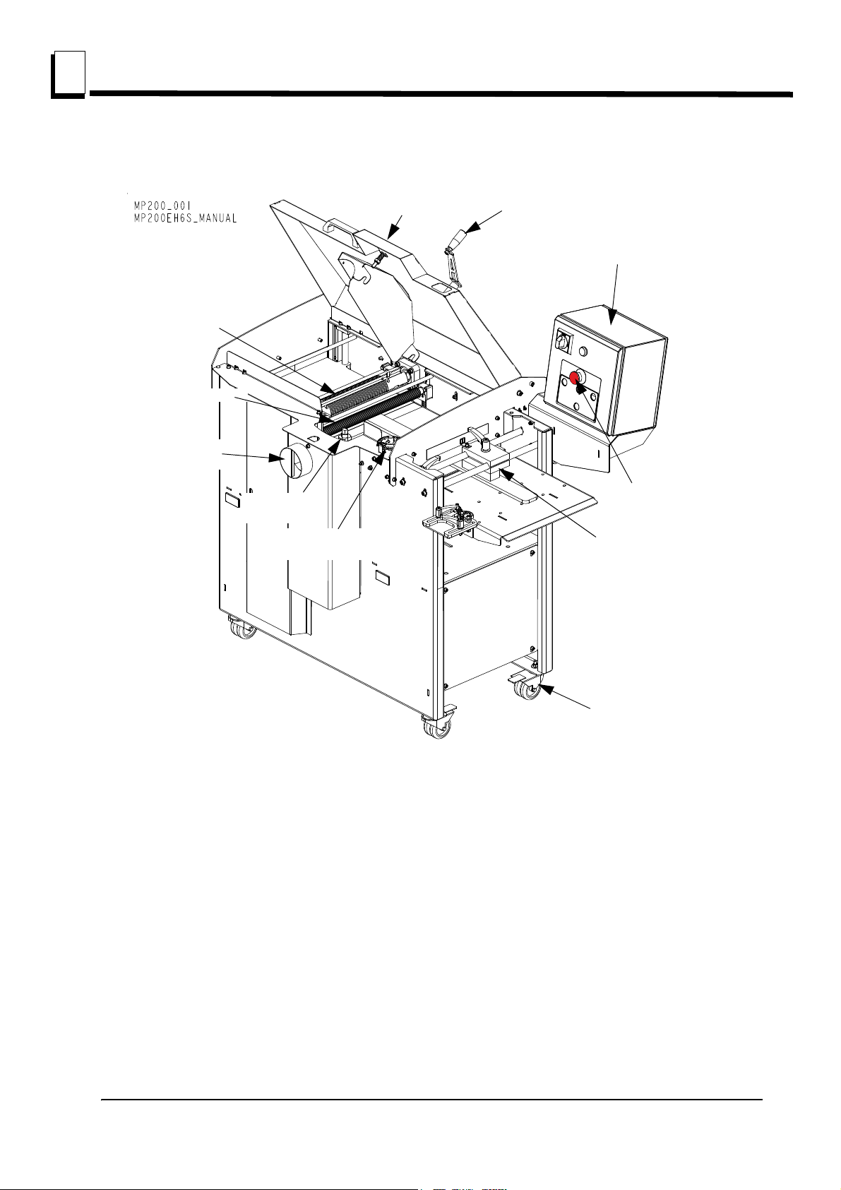
1.1 Machine description
The Wood-Mizer planer/moulder is designed for straight and profiled planing of wooden elements used
for the production of wooden houses and other construction elements used in building industry and
garden programs. All other uses of the planer are forbidden.
The MP200 is a planer/moulder that can work two sides of a workpiece in one action. The planer/
moulder is contained in a stable and strong chassis. The planer/ moulder table is made of planed cast
iron.
The workpiece is fed, lying on the planer table, through the planer by feed rollers as well as an outfeed
roller. The rollers are driven by a chain transmission with separate motor. The workpiece is controlled
laterally with adjustable fences and pressure rollers.
The work is done using a top cutter and side cutter which are fixed to the planer table. All the cutters are
driven by separate motors, via a belt transmission.
The cutters and feed rollers are covered by a protective cover plate. The cover plate is supplied with a
safety switch. A 100 mm (4”) dia. hose is connected to the cutter. A 100 mm (4”) dia. hose is connected
to the side cutter and a 125 mm (5”) dia. hose is connected to the top cutter.
TABLE SURFACE
Table is made with a highest quality cast. The table surface is specially processed for the highest
precision and the best anti-friction qualities.
When the planer/moulder is new, it requires a breaking-in period until the table gets a slightly shinier
surface to optimize the anti-friction qualities. During this period it is recommended to use a lubricant or
wax on the table.
Using the machine correctly, you will obtain a perfectly smooth surface and a high degree of accuracy.
The planer/moulder should be operated only by an adult who has read and understood the entire
operator’s manual.
Planer/moulder is built to be durable and easy to operate and maintain.
MACHINE AND SITE PREPARATION