Woodpeckers SW350 User manual

Made in the U.S.A. by Woodpeckers Inc., North Royalton, Ohio · Copyright 2010© Woodpeckers Inc. 8/10 Page 1
SAFETY
Always unplug your router motor before making any
adjustments to the router lift. Refer to your routers’ owners
manual for specific safe operating instructions.
BEFORE YOU BEGIN
The Woodpeckers®Side Winder can be installed in most
router tables with a standard 9¼ x 11¾ opening and a side
panel mounting surface no more than 19" away as in the
side of a cabinet or router table stand. In most cases three
holes will need to be drilled for mounting the side plate.
These instructions assume you’re installing the Side Winder
on a Woodpeckers® Router Table Stand.
Woodpeckers®Router Table Stand, Router Table and Side Winder.
COMPATIBLE ROUTER MOTORS
The Woodpeckers®Side Winder 350 Router Lift fits the
Porter-Cable 690/890, Bosch 1617/1618 and Craftsman
models 17542, 17540, 28190 router motors as well as any
router motors 3.5" in diameter.
Made in U.S.A. by Woodpeckers Inc.
Protected by one or more of the following U.S.
Patents; 6,505,659; 7,559,347; 7,481,253;
7,108,463 and other patents pending.
INSTALLATION INSTRUCTIONS
Models: SW350
Woodpeckers
PRECISION WOODWORKING TOOLS
®
Side Winder
Router Lift.
USING THE LIFT WRENCH
You’ll need to know how to use the Lift Wrench to install
your router motor.
STEP 1. To change the carriage height (the carriage is the
part beneath the table that holds the motor), orient the
wrench with the handle pointing right. (Figure 1.)
Insert the wrench until it’s COMPLETELY BOTTOMED OUT.
Once it’s all the way in, try and rotate it. If it doesn’t turn, it
isn’t in. Do not force the wrench. Take it out, push it back
down and try again.
STEP 2. Once it turns easily, simply rotate it ¼ turn in ei-
ther direction to lock the handle to the carriage. Now you
can raise or lower your router as needed using the wrench.
(Figure 2.)
To install your router motor you need to raise the carriage
all the way up and lock it in place by once again orienting
the handle to the right. Now remove the lift wrench.
Once fully
inserted, rotate
the wrench ¼
turn in either
direction and
completely raise
the carriage.
Carriage
Figure 2.
The wrench
handle must
be pointing
right in order
to fully insert
or remove it.
Lift Wrench
Figure 1.

Made in the U.S.A. by Woodpeckers Inc., North Royalton, Ohio · Copyright 2010© Woodpeckers Inc. 8/10 Page 2
STEP 6. Evenly snug the two knobs. They are self lock-
ing so they won’t spin freely. Before you finish tightening
the knobs, make sure that all parts of the router are well
clear of the two posts and lift rod. Figure 6 shows the ap-
proximate position of a PC 690 motor relative to the posts.
Now remove the coupling from the lift rod and set it aside
for later.
REMOVE THE RING
STEP 3. The Side Winder
comes with one ring in-
stalled. This ring needs to
be removed in order to in-
stall your motor. Loosen the
ring by turning it CLOCK-
WISE with the spanner wrench. To put one back in, rotate
it counter-clockwise.
Figure 3.
Figure 4.
INSTALLING YOUR ROUTER MOTOR
STEP 4. Make sure the carriage has been raised to the
top, locked and the lift wrench has been removed. Then
remove the lift from the table, flip it over and set it back into
the table opening as shown in Figure 4.
Carriage adjusted
close to plate.
No ring.
Figure 6.
Clearance.
Remove coupling
after motor is
clamped in.
Knobs.
Clamp.
Carriage.
STEP 5. Make sure the clamp knobs are backed off enough
to allow your motor to slide in. Loosely set a coupling on
the lift screw. (Figure 5a). Slowly drop the router into place.
Support the motor so it just begins to go through the open-
ing in the plate. (Figure 5b).
Figure 5b.
Clamp knobs.
Figure 7a.
INSTALL THE TWO CLAMP BLOCKS
STEP 7. Carefully study Figure 7a. Thread one of the small
T-knobs onto a 3" long bolt with the top of the knob going
on the bolt first, toward the hex
head. Now slip a clamp block
onto the bolt oriented as shown
above with the flat side facing
the knob. Then thread a hex nut
about ½" up the bolt. And finally,
thread the bolt into the threaded
hole centered near the short
edge of the plate. If needed, use
a 7⁄16" wrench to lightly snug the
bolt into the plate. (cont’d.)
Clamp block.
T-knob.
3"long bolt.
Hex nut.
Short edge of plate.
Figure 7b.
Figure 5a.

Made in the U.S.A. by Woodpeckers Inc., North Royalton, Ohio · Copyright 2010© Woodpeckers Inc. 8/10 Page 3
SIDE CRANK INSTALLATION ON A
WOODPECKERS®ROUTER TABLE STAND
This section assumes you’re installing the Side Winder onto
a Woodpeckers®Router Table Stand.
STEP 9. Remove the existing hex bolt from the inside cor-
ner of the router table stand and attach the side panel using
one of the connector bolts and hex nuts. (Figure 9).
Figure 9.
Side panel.
Connector bolt.
STEP 11. First slip the pin into a coupling until it bottoms
out. Tighten the set screw onto the flat of the pin. Now
push the flex shaft into the other end of the coupling. Tight-
en the remaining set screw onto the flex shaft. Now loosen
the first set screw and remove the pin. You’ll need it for the
next step. (Figure 11).
Figure 11.
1st 2nd
Pin.
Flex shaft.
Coupling.
Figure 12.
STEP 12. Insert the pin into the
remaining coupling and tighten
the set screw on the flat just like
before. Set the coupling aside
for now and thread the bare end
of the flex shaft up through the
bearing in the bracket. Secure
the coupling onto the end of the
flex shaft. Now both ends of the
flex shaft should have couplings
attached and the end going up
through the bracket should have
the pin installed as well. (Figure
12).
STEP 10. Using the side panel as a guide, drill two 9⁄32 dia.
holes through the router table stand. Fasten the panel in
place using the remaining two connector bolts and nuts.
(Figure 10).
Drill 9⁄32 hole in these
two locations.
Figure 10.
Figure 8.
Clamp block.
Clamp knob.
STEP 8.
Once your router motor and the two clamp blocks
have been installed, remove the Side Winder from the table
and set it back in, right side up. From underneath the table
rotate the clamp blocks in place and tighten the two knobs.
The clamp blocks hook under the edge of the table opening.
(Figure 8).
Flex shaft.
Bracket.
DO NOT OVERTIGHTEN THE BOLT. Overtightening will
damage the plate. Snug the hex nut against the plate. (Fig-
ure 7b). Repeat the same steps for the other clamp block.

Made in the U.S.A. by Woodpeckers Inc., North Royalton, Ohio · Copyright 2010© Woodpeckers Inc. 8/10 Page 4
Figure 15.
STEP 15. Install the brake knob into the threaded hole in
the handle. (Figure 15). Do not tighten the brake knob until
it’s needed. It’s typically used when doing heavy routing.
STEP 16. Rotate the crank handle so that the set screws in
the coupling on the other end of the flex shaft align to the
flat spot on the lift rod. Slip the coupling onto the lift rod
and tighten the screw. (Figure 16).
Figure 16.
Flat on lift rod.
Coupling / set screw.
TESTING THE CRANK ASSEMBLY
Test the crank assembly by slowly turning the handle and
watching the round scale on the top of the lift. If the scale
isn’t turning when you’re rotating the crank handle then one
of the set screws isn’t tight. It’s most likely to be one of the
set screws at either end of the flex shaft locking it to the
coupling. Double check that those two screws are tight.
After that make sure that the set screws in the handle and
couplings are against the flats on each shaft.
SIDE WINDER INSTALLATION ON
NON-WOODPECKERS®ROUTER TABLE STANDS.
The Woodpeckers® Side Winder can be installed on non-
Woodpeckers®cabinets and router table stands. The
above illustration shows the general location of the crank
handle relative to the router table top and router lift. It’s rec-
ommended that the side panel be mounted in its entirety
and not disassembled.
STEP 14. From the outside, slip the crank handle onto the
pin, align the end of the pin with the face of the handle,
align the set screw with the flat spot on the pin and tighten
the screw. (Figure 14).
Double check that the handle has a little bit of in and out
play. If it’s tight, the handle will not crank freely.
Figure 13.
STEP 13. Apply a dab of grease to the outside of the pin
and insert it through the hole in the bolt. This will take
some effort. Be careful not to kink the flex shaft. Bend
it just enough to get the pin through the hole. Optionally
you can loosen the large bolt holding the bracket to the
side panel. Do not completely remove the bolt. When fin-
ished m
ake sure the bracket is hanging straight down and
re-tighten the large bolt.
(Figure 13).
Figure 14.
6"- 8"
Position of side crank.
Lift rod.
4"- 5"
Set screw.

Made in the U.S.A. by Woodpeckers Inc., North Royalton, Ohio · Copyright 2010© Woodpeckers Inc. 8/10 Page 5
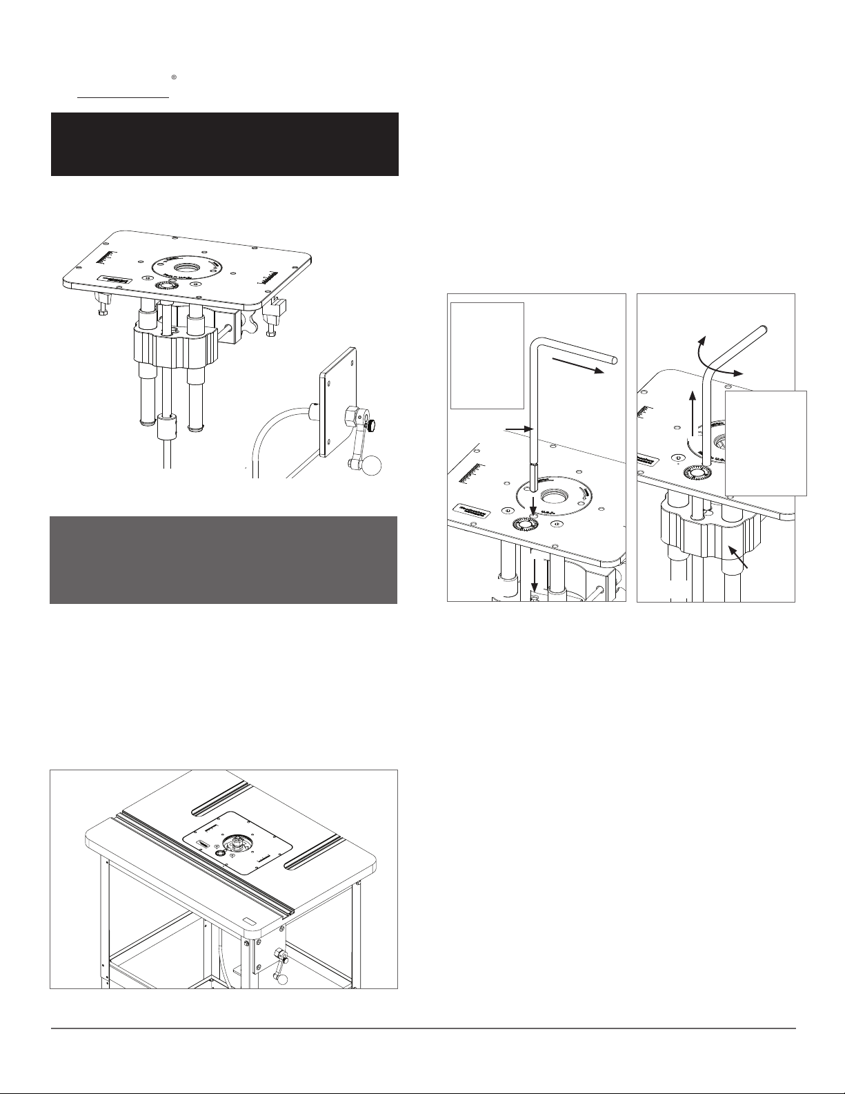
LEVELING THE PLATE
Before adjusting the leveling
screws you need to loosen
the clamp knobs underneath
the table. There are eight set
screws around the perimeter
for adjusting the height of the
plate relative to the table. Initial
leveling should be done with
just four of the screws, two each on opposite ends of the
plate. Once the plate feels flush, use a block of wood to
make sure it doesn’t catch going either direction then ad-
just the remaining screws.
CHANGING BITS
First use the spanner
wrench to remove the Twist
Lock Ring. Now use the lift
wrench to raise the router
chuck completely above
the plate. Use the wrench-
es supplied with your rout-
er to change the bit. (Image
may not match your Side
Winder but the process is
the same.
GENERAL OPERATING INFORMATION
ROUTINE MAINTENANCE
The Side Winder is made primarily from aluminum and steel
parts. The steel parts will have a light coating of petroleum
jelly when it leaves the factory. After unpacking, if necessary,
clean aluminum parts, including the main plate, with mineral
spirits or lacquer thinner. Do not use any water based cleaner.
The two steel posts should be wiped with a clean rag and
lubricated with petroleum jelly or a very light machine oil. The
flex shaft can be periodically sprayed with a lubricant such as
WD40 then wiped dry.
Minor surface rust on any steel parts can be removed with
abrasive nylon pads like a scotch bright pad. All steel parts
should be kept lubricated with petroleum jelly or thin machine
oil, particularly the posts and lift screw.
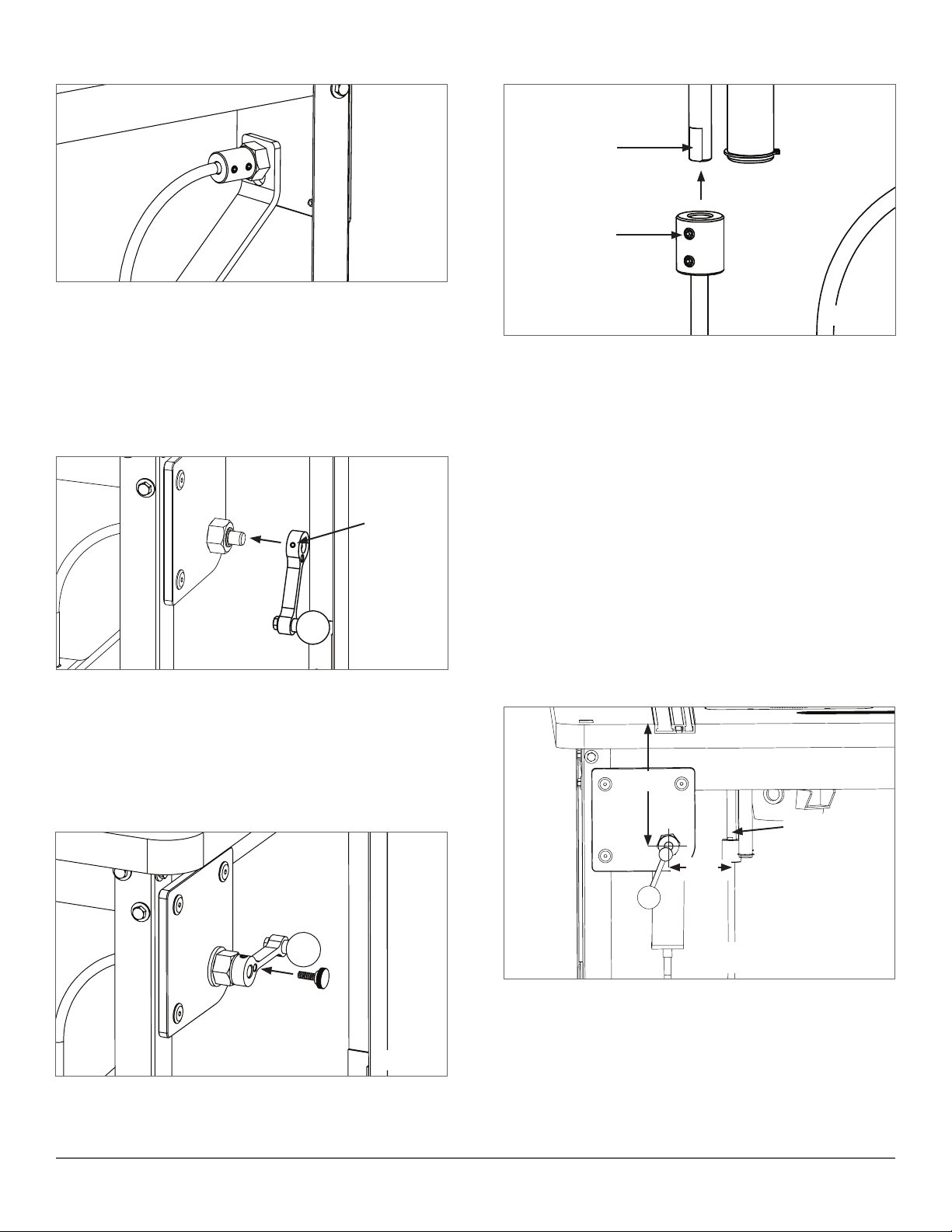
ADJUSTING THE SCALE
The adjustable scale is used
to reference the amount of
height change relative to a
starting position. One rota-
tion equals 1⁄32". Each line
equals .001".
The scale
can be adjusted by apply-
ing downward finger pres-
sure then rotating it in either
direction. Built in friction
keeps it from free spinning.
Adjustable scale.

www.incra.com
®
Manufactured by:
Taylor Design Group, Inc.
P.O. BOX 810262 Dallas, TX 75381
www.incra.com
INCRA is a Registered Trademark of Taylor Design Group
©2021 Taylor Design Group, Inc. 11/10
Side Winder Side Crank Installation on INCRA
Router Table Stands
Note: This addendum replaces Fig/Step 10 & Fig/Step 11 of the Woodpecker provided mounting instructions.
Please follow all assembly instructions of the original manual up to Fig/Step 10 before using this addendum.
MADE IN THE
USA
If your INCRA router table stand is already assembled you will first need to remove the table top and remove the
front top stretcher. Remove the lower 1/4-20 x 1/2” hex bolt from the left end of the stretcher, Fig. 1. Loosely
attach the Side Winder Crank’s side panel to the stretcher using the provided 1/4-20 x 7/8” hex bolt, washer
and square nut. Place another 1/4-20 x 7/8” hex bolt with washer
through the lower hole on the Crank’s side panel and add the large
gold washer to the fastener before loosely threading on the square
nut, Fig. 2.
Re-assemble the stretcher to the stand sliding all 3 of the square
nuts on the left end of the stretcher into the t-slot in the leg.
Make sure the Crank’s
side panel is parallel
to the leg before
tightening all of the
mounting bolts,
Fig. 3.
Using the remaining
hole in the side
panel as a guide,
drill a 9/32” hole
through the front
stretcher, Fig. 4.
Place a flat washer
on the remaining 1/4-20 x 7/8” hex bolt and insert through the
hole on the side panel. Add a split lockwasher and a square nut
then tighten the assembly in place, Fig. 5.
Continue with Fig/Step 12 in the Side Winder Owner’s Manual.
Fig.1
Fig.2
Remove front
stretcher and remove
lower hex bolt from
left end
Fig.4 Fig.5
1/4-20x7/8
hex bolt with
washers
Square
nuts
Large washer
this bolt only
Square nuts
captured in
T-Slot on Leg
Re-assemble Stretcher to Stand
Fig.3
Drill 9/32”
hole through
stretcher
1/4-20x7/8
hex bolt with
washer.
Secure with
lockwasher
and
square nut

www.incra.com
®
Manufactured by:
Taylor Design Group, Inc.
P.O. BOX 810262 Dallas, TX 75381
www.incra.com
Side Winder Side Crank Installation on
INCRA Table Saw Systems
Note: This addendum replaces Fig/Step 10 & Fig/Step
11 of the Woodpecker provided mounting instructions.
Please follow all assembly instructions of the original
manual up to Fig/Step 10 before using this addendum.
MADE IN THE
USA
Add a large flat washer to each of the 3/8-16 x 3/4” hex bolts and
thread a 3/8-16 rectangular nut onto the end of each bolt.
Slide the rectangular nut on each of the bolt assemblies into the
T-slot located on the underside of your INCRA TS System’s front
rail and position the bolts close to your router, Fig. 1. (You’ll be
able to adjust the final position after full assembly.)
Slide the slotted end on each
of the mounting brackets all the
way onto the bolts as shown
in Fig. 2 then position the
brackets so that the 2 holes
are approximately 4- 1/4” apart.
Finger tighten the 2 bolts.
Attach the Side Winder Crank’s
side panel to the brackets using
(2) 1/4-20 x 1-1/2” hex bolts with
washers and hex nuts, Fig. 3.
Be sure to place a split lock washer on the end of the bolt before
threading on and tightening the hex nuts. Tighten the (2) 3/8-16
hex bolts that secure the brackets to the underside of the rails.
Continue with Fig/Step 12 in the Side Winder Owner’s Manual.
TIP: Moving the bracket/crank assembly to the left or right along
the rail can improve how easily you are able to rotate the crank
handle. After you have attached the flex shaft to your router,
try sliding the bracket/crank assembly to different positions left
or right to find the easiest crank rotation. In general, the more
relaxed the lower loop or “U-turn” is on the flex shaft, the easier
the crank will rotate.
Fig.1
Fig.2
Rectangular
nut captured
in T-slot
Mounting
brackets4-1/4”
Side
panel
Fig.3
3/8-16 x 3/4
hex bolts
with washer
1/4-20 hex
bolts with
washers &
hex nuts
INCRA is a Registered Trademark of Taylor Design Group
©2021 Taylor Design Group, Inc. 11/10
Other Woodpeckers Tools manuals