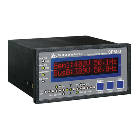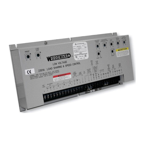
Manual 37134D SPM-D10/YB - Synchronizing Unit
© Woodward Page 3/50
Revision History
Correction: Wide-range power supply (wiring diagram, power supply)
Improved: Controller setting description, wide-range power supply, technical data; language review
Minor corrections; Package harmonization
Voltage range changed from “90 to 250 Vac/dc” to “90 to 250 Vac”.
Protection (from back) changed from “IP21” to “IP20”.
Contents
CHAPTER 1. GENERAL INFORMATION ........................................................................................6
CHAPTER 2. ELECTROSTATIC DISCHARGE AWARENESS .............................................................7
CHAPTER 3. INSTALLATION.......................................................................................................8
Wiring Diagram .........................................................................................................................................9
SPM-D10/YB...................................................................................................................................9
SPM-D10/NYB..............................................................................................................................10
Reference Point.......................................................................................................................................11
Power Supply ..........................................................................................................................................11
Measuring Inputs.....................................................................................................................................12
Mains/System U1..........................................................................................................................12
Generator/System U2 ...................................................................................................................12
Discrete Inputs ........................................................................................................................................13
Relay Outputs..........................................................................................................................................14
Controller Outputs...................................................................................................................................14
CHAPTER 4. DESCRIPTION OF FUNCTIONS ...............................................................................15
Functionality............................................................................................................................................15
Table of Functions ........................................................................................................................15
Control Inputs..........................................................................................................................................16
Isolation of the Power Supply from the Discrete Inputs...........................................................................16
Operating Conditions...............................................................................................................................17
No Load Control............................................................................................................................17
Synchronizing................................................................................................................................17
Dead Bus Start (Asynchronous Add-On)......................................................................................18
Synch-Check.................................................................................................................................18
Control Outputs.......................................................................................................................................19
CHAPTER 5. DISPLAY AND OPERATING ELEMENTS...................................................................20
Brief Explanation of the LEDs and Push Buttons....................................................................................21
LEDs .............................................................................................................................................21
Buttons..........................................................................................................................................21
Others ...........................................................................................................................................21
LEDs........................................................................................................................................................22
Push Buttons...........................................................................................................................................24
LC Display...............................................................................................................................................25
Display Monitoring in Automatic Mode: Double Voltage/Frequency Display.................................25
Display Monitoring in Automatic Mode: Alarm Indication..............................................................25


