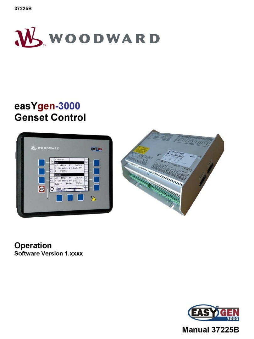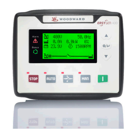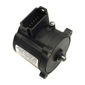
Manual 26247 2301D/2301D-EC Digital Control
Woodward i
Contents
REGULATORY COMPLIANCE ........................................................................V
ELECTROSTATIC DISCHARGE AWARENESS ................................................. VI
CHAPTER 1. GENERAL INFORMATION...........................................................1
Description..............................................................................................................1
Applications ............................................................................................................2
Control Options.......................................................................................................3
References .............................................................................................................3
CHAPTER 2. INSTALLATION..........................................................................9
Introduction.............................................................................................................9
Unpacking...............................................................................................................9
Power Requirements..............................................................................................9
Location Considerations.........................................................................................9
Electrical Connections..........................................................................................10
Shields and Grounding.........................................................................................10
Setting Speed Range ...........................................................................................11
Potential Transformer Connections......................................................................11
Current Transformer Connections........................................................................11
Load Sharing Lines...............................................................................................12
Power Supply .......................................................................................................12
Discrete Inputs (Terminals 28–38).......................................................................13
Close to Run or Minimum Fuel (Terminal 31) ......................................................13
Digital Inputs B, C, D (Terminals 32, 33, 34)........................................................14
Failed Speed Override..........................................................................................14
Reset ....................................................................................................................14
Select 2nd Dynamics.............................................................................................15
Shutdown Internal.................................................................................................15
Shutdown External ...............................................................................................15
Rated Speed.........................................................................................................15
Idle/Rated Software Switch ..................................................................................16
CB Aux/Droop Contact.........................................................................................16
Raise Speed/Load Contact (Terminal 35)............................................................17
Lower Speed/Load Contact (Terminal 36) ...........................................................17
Load Generator (Terminal 37)..............................................................................18
Base Load (Terminal 38)......................................................................................18
Actuator Output ....................................................................................................18
Analog Inputs........................................................................................................18
Analog Input #1 (Terminals 19-20).......................................................................19
Analog Input #2 (Terminals 22-23).......................................................................20
Speed Sensor (Terminals 25-26).........................................................................20
Relay Driver Outputs (Terminals 41–44)..............................................................20
Analog Output #1 (Terminals 16-17)....................................................................21
Communication Port.............................................................................................21
Installation Check-out Procedure.........................................................................25
CHAPTER 3. ENTERING CONTROL SET POINTS...........................................26
Introduction...........................................................................................................26
Watch Window PC Interface.................................................................................26
Configure Menu Descriptions...............................................................................28
Service Menu Descriptions...................................................................................34
