Workhorse Mach Series User manual

Owner’s Manual
Mach Series
3730 E. Southern Avenue, Phoenix, AZ 85040 USA
800-778-8779 Workhorseproducts.com 1

Table of Contents
3730 E. Southern Avenue, Phoenix, AZ 85040 USA
800-778-8779 Workhorseproducts.com 2
I. Introducon …………..…………………………...………………….……….…….……….. 3
II. Specicaons …..……………..………………………...………….………..………….…. 4
III. Parts for Assembly …..……………..……………………….….………….…….………. 5
IV. Assembly
Step 1: Inserng Levelers and Casters ……..……………………….…….……… 6
Step 2: Installing the Print Head …………………………………….….…….……. 7
Step 3: Installing the Print Arms ……….………………..………………...….……. 8
Step 4: Aaching the Platens …………………….…………..…………….…..……. 9
V. Print Head and Micro Adjustments ……………………..………………...…...…. 10
VI. Maintenance and Troubleshoong …………………………….………….…...… 12
VII. Parts List …………………………………………………………………………..……....… 13
VIII. Limited Warranty ………………………………………………………….………….… 14

Introducon
3730 E. Southern Avenue, Phoenix, AZ 85040 USA
800-778-8779 Workhorseproducts.com 3
Congratulaons on your purchase of the Mach Series.
Check the crate for damages. DO NOT accept the crate if there are any damages caused by improper han-
dling during shipping. Immediately report any damages to the carrier and contact Workhorse Products at,
800-778-8779.
Be sure to inspect the crate contents IMMEDIATELTY, while the carrier is sll present. Even though our pack-
aging has been designed to handle normal shipping condions, we cannot foresee damages done by the car-
rier. We will not be responsible for damages that occur during transportaon.
If there are damages immediately nofy the driver, le a claim with the carrier and call Workhorse Products.
The Importance of the Owner’s Manual:
The purpose of the Owner’s Manual is to familiarize you with the parts and operaons of the Mach Series.
There are step-by-step instrucons to assemble the press, accompanied with links to videos for further assis-
tance. Also included are explanaons of the product’s key features, and addional informaon that will help
with the maintenance of your press.

Specicaons
3730 E. Southern Avenue, Phoenix, AZ 85040 USA
800-778-8779 Workhorseproducts.com 4
4 Color, 4 Staon
Max Screen: 32" (81CM)
Dimensions: 103” x 34-36”
M-44-M
8 Color, 6 Staon
Max Screen: 21" (53CM)
Dimensions: 111” x 34-36”
M-86-O
6 Color, 4 Staon
Max Screen: 23" (58CM)
Dimensions: 103” x 34-36”
M-64-O
6 Color, 6 Staon
Max Screen: 26" (66CM)
Dimensions: 111” x 34-36”
M-66-M
8 Color, 8 Staon
Max Screen: 26" (66CM)
Dimensions: 130” x 34-36”
M-88-O
10 Color, 8 Staon
Max Screen: 23" (58CM)
Dimensions: 130” x 34-36”
M-108-O

Parts for Assembly
3730 E. Southern Avenue, Phoenix, AZ 85040 USA
800-778-8779 Workhorseproducts.com 5
Descripon Part Number
Print Arm Pre-Assembled
Platen (15” x 18”) 12015
Print Head Spring 71010
Nylon Neng 10-8000
Hog Ring 71007
Hex Bolt (1.25” x
40mm)
41-HTB-M8-20
Descripon Part Number
1/2” Flat Washer 43-FLT-M12-10
Roll Pin 45-1260
Base Pre-Assembled
Hex Bolt (1.5”x 25mm) 41-HB-M10-20
Leg Levelers (1.75”x
60mm)
41-HTB-M12-30
The quanty of parts diers depending on the specic model being assembled. In this manual a 6 Color/ 4
Staon Mach Series Manual Press is being assembled. The quanty of parts will not match if assembling
another model of the product.

Assembly
3730 E. Southern Avenue, Phoenix, AZ 85040 USA
800-778-8779 Workhorseproducts.com 6
Step 1: Inserng levelers/casters.
Tools needed:
3/4” Wrench and
Socket
3/4” Wrench and
Socket
Parts needed:
4 x Levelers/Casters
Base
1. Install the leveling nut onto the leveling bolt unl
it’s 1” from the bolt head. When installing the levelers
ensure that they are all the same height. Use a 3/4”
wrench on the head of the bolt and a 3/4” wrench on
the nut to ghten. Repeat this process for each leg on
the press
2. To install the caster system thread the top of the
bolt into the boom of the press, where the levelers
would be installed. Thread unl the very boom.
3. Aer the casters are threaded by hand, use a 3/4”
deep socket wrench to ghten.

Assembly
3730 E. Southern Avenue, Phoenix, AZ 85040 USA
800-778-8779 Workhorseproducts.com 7
Step 2: Installing the print head.
5. Aer both springs and hog rings
are aached, push down the print
head to insert a stop bolt with a 1/2”
washer into the upper hole of the
print head.
6. Screw on a 1/2” washer and a lock
nut onto the other side of the bolt.
Tighten the stop bolt by hand as much
as possible. Repeat steps 1-6 for every
print head on the press.
Parts needed:
6 x Stop Bolts
12 x Hog Rings
12 x Nylon Nengs
12 x 1/2” Flat Washers
12 x Lock Nuts
1. Raise the print head and insert
a spring into the boom-le hole
of the aachment arm bracket.
2. Cover the spring with nylon
neng and leave the top of the
spring exposed.
3. Connect the hog ring to the
spring and then hook the hog ring
onto the print head. Use the hole
closest to the print head.
4. Pull the nylon neng over
the hog ring to cover the enre
assembly. Repeat steps 1-3 for
the other side of the print
head.

Assembly
3730 E. Southern Avenue, Phoenix, AZ 85040 USA
800-778-8779 Workhorseproducts.com 8
Step 3: Installing the print arms.
Tools needed:
Hammer
3/4” Socket
Wrench
Parts needed:
16 x Hex Bolts (1.5” x 25mm)
16 x Flat Washers (1/2”)
8 x Roll Pins
1. It’s very important to match the
numbers on the print arm with the
numbers on the base. These are factory
set for proper leveling and alignment.
Align the holes on the print arm with
the holes on the base.
2. Insert a bolt (1.5”x 25mm)
and 1/2” at washer into the
top-right corner rst and the
boom-le corner second.
Only ghten by hand for now.
3. Insert a roll pin into the middle-right
hole rst, followed by the middle-le hole
second. Aer both pins are inserted by
hand, lightly hammer them so it inserts
into the hole of the press base. Leave 1/4
of the pin exposed.
4. Aer both spring pins are installed, insert the other
two hex bolts and at washer so that every corner hole
is lled.
5.Aer installing the two bolts with the washers, ghten
them with a 3/4” socket wrench. Do not overghten to avoid
compressing the print arm. Repeat steps 1-5 for every print
head. Don’t adjust the bolts on the support arm, which are
located under the print arm.

Assembly
3730 E. Southern Avenue, Phoenix, AZ 85040 USA
800-778-8779 Workhorseproducts.com 9
Step 4: Aaching the platens.
Parts needed:
Platens
1. Lower one of the print heads and slide
the platen onto the print arm unl it’s 1/2”
from the end of the screen clamp. Securely
ghten the boom knob. Repeat for every
print head.
Congratulaons! The Mach Series is now
fully assembled.
Remember, don’t adjust the bolts and nuts located on the support arms. They are factory set for proper
leveling and alignment. One of the many advantages of the Mach Series is that when it’s manufactured it’s
also fully assembled, making it leveled and inspected at the factory. This quality control process is to ensure
success when assembling the press on locaon.

Print Head and Micro Adjustments
3730 E. Southern Avenue, Phoenix, AZ 85040 USA
800-778-8779 Workhorseproducts.com 10
(A) O Contact Adjustment Knob
(B) X and Y Micro Adjustments
(C) Micro Lockdown Knobs
(D) Side-to-Side Adjustment
(E) O Contact Jam Knob
(F) Screen Lockdown Knobs
(G) O Contact Clamp & Screen Holder
(H) Screen Tilt Adjustment
(H1) Screen Tilt Jam Nut
(H2) Screen Tilt Ring
(I) O Contact Foot Pad
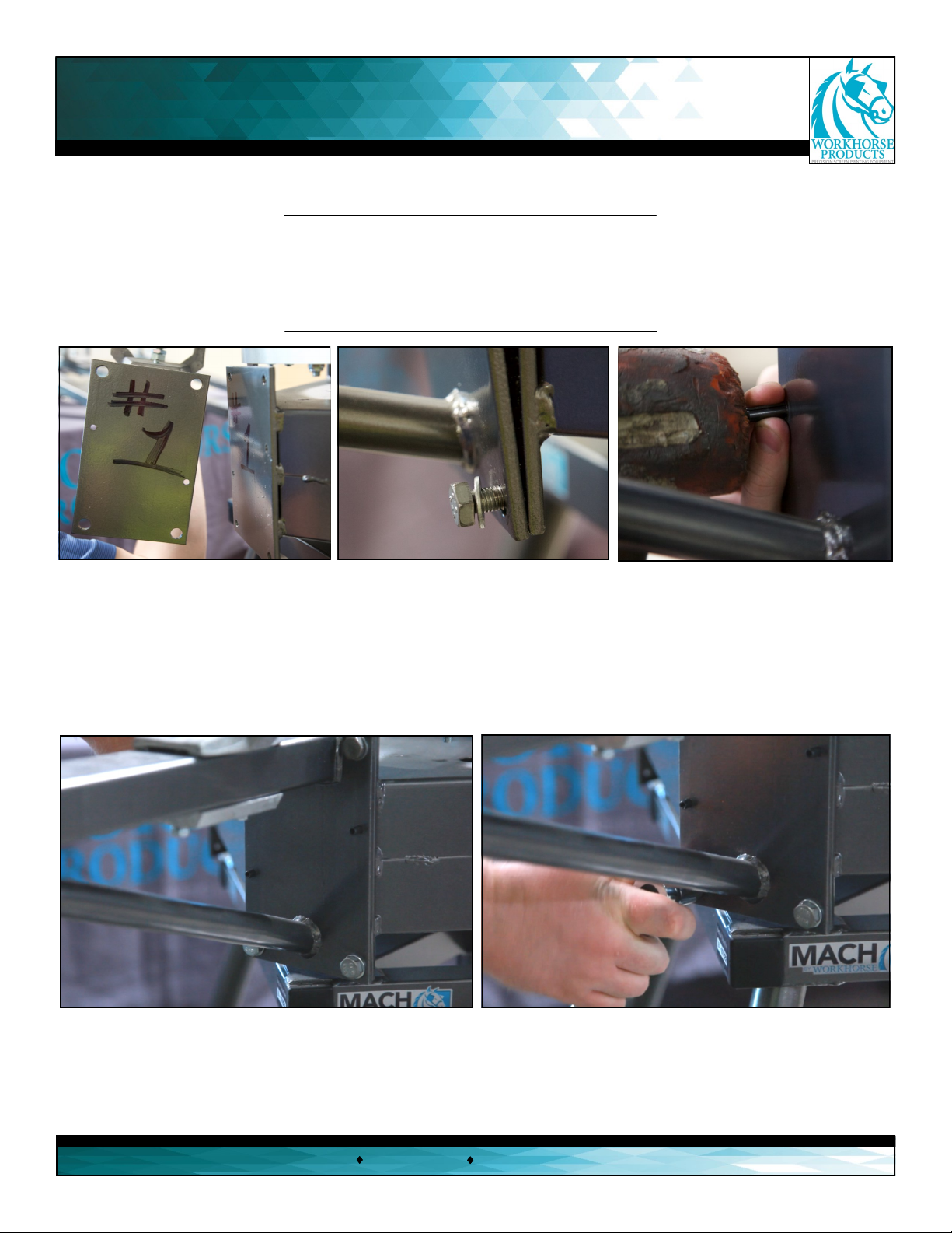
Adjusng the O Contact: (A, E & I)
Even though the Mach is automacally set at a
standard o contact, there will be instances that
require adjusng it. To adjust, loosen the o contact
adjustment knob (A) and unscrew/screw down the
o contact adjustment knob to adjust the foot pad
(I) to the desired o contact. Tighten the jam knob
(E) to prevent the o contact knob (A) from moving,
avoid over ghtening.
(A)
(C) (B)
(B)
(C)
(D)
(D)
(E)
(F)
(F)
(G)
(H)
(H1)
(H2)
(I)
(B) (B)
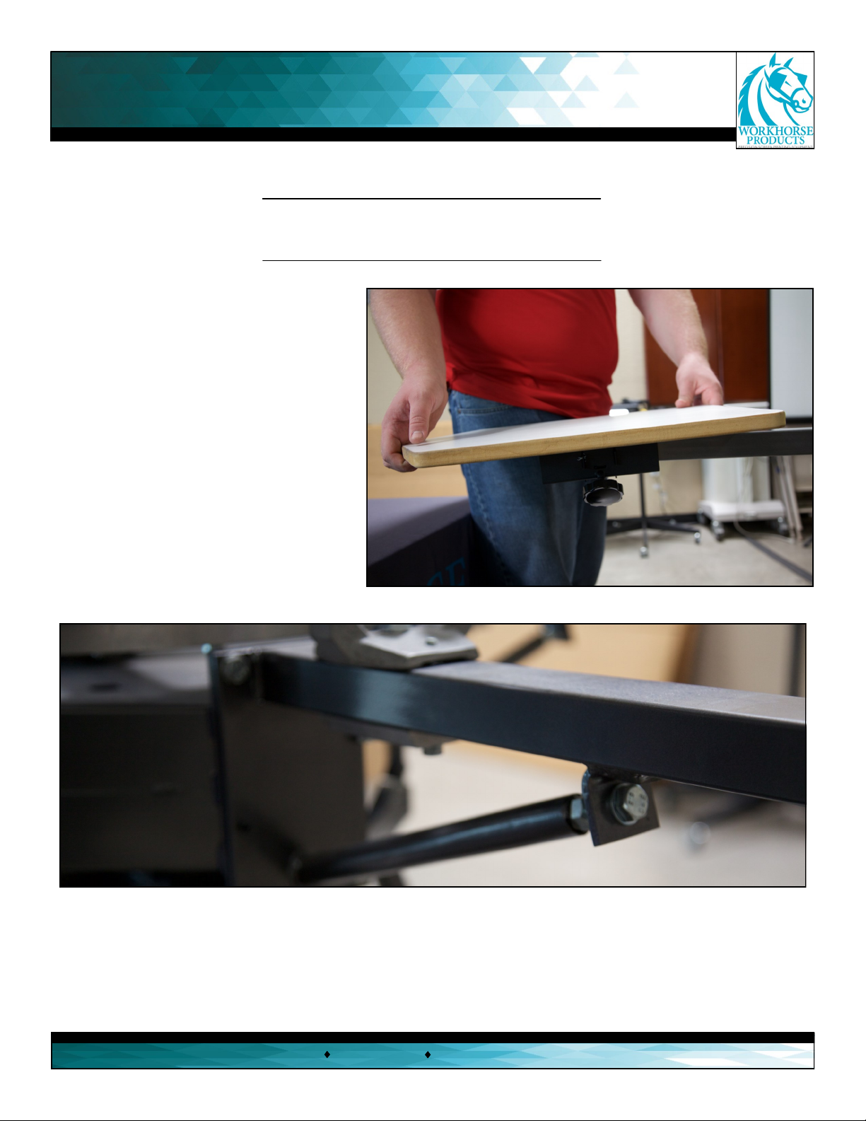
Adjusng the Screen Tilt: (H, H1, & H2)
First, loosen the screen lt jam knob (H1) to create
room to adjust the screen lt and loosen the screen
lt knob (H). Hold the screen and lt it so that the
screen is parallel with the pallet. Then ghten the
screen lt jam knob (H1) unl it’s against the
screen lt ring (H2). While holding the screen lt
jam knob, ghten the screen lt knob unl it ght-
ens the screen lt jam knob against the screen lt
ring.
Tip: To set the o contact consistently, use two 16x1”
10mm strips of plasc for each distance. Place one strip
on the platen and one at the front and back of the
screen ,adjust the screen lt (H) unl it makes contact
with both strips. This will ensure that the front of the
screen is parallel with the back of the screen.

Print Head and Micro Adjustments
3730 E. Southern Avenue, Phoenix, AZ 85040 USA
800-778-8779 Workhorseproducts.com 11
Using the X and Y Micro Adjusters: (C)
Always loosen the micro lockdown knobs (C) before adjusng the micros. To adjust the registraon turn the X and Y
micro adjusters (B). To move the screen le/right or up/down use the micro adjusters (B). To move the screen up/
down without moving it to the le/right, turn both micro adjusters at the same me. Aer adjustments are nished
ghten the micro lock down knobs (C), but don't over ghten.
Using the Side-to-Side Micro Adjuster: (D)
Always loosen the micro lock down knobs (C) before beginning the adjustment. Turn the side-to-side micro adjuster
to move the screen side to side, to properly set it must be used in conjuncon with the X and Y micro adjusters (B). To
ulize the full range of movement both sets of adjusters must be used. Always center the micros either aer com-
pleng a job or beginning one, because it will save a lot of movement.
The Register Gate and Bolt:
The print dead has a register locater aached under the micro lockdown knobs (C), which ts into the register gate in
order to center the screen. The two plasc bolts are used to adjust the centering of the screen. The bolts will eventually
wear down, so it’s essenal to adjust the bolts to keep the screen centered.
Locking Down a Screen:
To place a screen in the print head, loosen the two screen lockdown knobs (F) and raise the screen lockdown clamp bar
(G) unl the screen can t in. Then push the screen all of the way to the back of the screen clamp. Aer the screen is
properly placed ghten the two screen lockdown knobs, but don’t over ghten.
Tip: When using a back clamp prinng press always measure the design height from the back of the screen, to conrm
the design will register even when using dierent size screens.
(A)
(B) (B)
(C)
(C)
(D)
(E)
(F)
(F)
(G)
(H)
(H2)
(H1)
(I)
(A) O Contact Adjustment Knob
(B) X and Y Micro Adjustments
(C) Micro Lockdown Knobs
(D) Side-to-Side Adjustment
(E) O Contact Jam Knob
(F) Screen Lockdown Knobs
(G) O Contact Clamp &
Screen Holder
(H) Screen Tilt Adjustment
(H1) Screen Tilt Jam Nut
(H2) Screen Tilt Ring
(I) O Contact Foot Pad

Maintenance and Troubleshoong
3730 E. Southern Avenue, Phoenix, AZ 85040 USA
800-778-8779 Workhorseproducts.com 12
The Mach Series does not require much maintenance, but periodic lubricaon and cleaning will ensure smooth opera-
on and extended life of the components. Wipe the press daily to remove spray adhesive and lint. Do not let the
spray adhesive and lint accumulate.
To lubricate use heavy duty wheel bearing grease. Unscrew the (B)
micro lock down knobs and both of the nuts that aach the micro
adjusters to the micro plate, li up a lile and put grease under the
micro plate to provide easy movement of the micros.
To lubricate the micros back o the adjusters so most of the thread
shows, apply a small dab of grease and work into the threads. Then
screw down to reveal the other side and then repeat for the other
side. Aer all of this, re-center the micros.
Don't forget to grease the o contact bolt head that is located in the in-
side of the o contact clamp and screen holder. Loosen the o contact
bolt and pull the large bolt head out slightly, then apply grease on the
threads and the print head pivot bolt.
Do not grease the white plasc print head centering bolts
Micro Plate
O Contact
To lubricate the carousel center oat arms, just apply grease under the
arms. Do not aempt to loosen or adjust the center cap.
To clean the press avoid using alcohol based solvents. Oil based paint
thinner is beer, because it won't cut and dry out the grease.
Troubleshoong
If there are issues turning any of the knobs or micro adjusters, check to
see that they are not gummed up with spray adhesive or ink. Also,
make sure they are being clean with an oil based solvent and lubricate.
If the carousel becomes s or too easy to rotate, check to see that the
top tension nut is not too ght or loose because it will determine if the
tapered bearings need grease. Take o the jam nut to reach the re-
sistant nut.
Carousel Center Float Arms
(B) (B)
Jam Nut
Resistance
Nut

Parts List
3730 E. Southern Avenue, Phoenix, AZ 85040 USA
800-778-8779 Workhorseproducts.com 13
Pallets:
Descripon: Top w/ bracket Standard Top Aluminum Top
10 x 14 youth 12010 12110 12180
15 x 18 adult 12015 12120 12181
18 x 20 oversize 12020 12130 12182
Vacupallet Graphics Prinng Pallet:
Vacuum Pallet with bracket, pump and footswitch 18 x 24 Part no. 12513
EZ-CAP Cap Prinng Pallet:
E-Z Cap Pallet 3 x 4.75 w/110 Cap Screen and Squeegee Part no. 12011
E-Z Cap Screen #110 Mesh Part no. 12012
E-Z Cap Screen #124 Mesh Part no. 12013
Gripper Jacket Prinng Pallet:
EZ-Pocket Pocket Prinng Aachment:
E-Z Pocket Pallet EZP 4 x 4 Part no. 12005
Complete arm assembly. Includes everything to add a print staon 21001R
Nylon Registraon bolt kit. Includes Lock nut Package of 12 73007R
Spring and Ext. Hog Ring kit. Package of 12 71010R
NOTE: these should be replaced annually !!
Y-axis Adjusng assy. Knob and nylon eye bolts Package of 2 20005R
Knob, micro cinch Package of 2 74006R
Screen Clamp Knob Package of 2 74011R
Part no.
Descripon

Limited Warranty
3730 E. Southern Avenue, Phoenix, AZ 85040 USA
800-778-8779 Workhorseproducts.com 14
Although every eort has been made to provide accurate specicaons, Workhorse Products does not assume any liability
for damages, whether consequenal or incidental, that may result from the use or misuse of the indicated specicaons.
Workhorse Products requires the use of a licensed industrial electrician for the installaon of electrical service to equip-
ment requiring electrical power.
Workhorse Products reserves the right to alter specicaons in the manufacture of its products. It is understood and agreed
that Seller’s liability for any equipment whether liability in contract, in tort, under any warranty, in negligence, in strict liability
or otherwise shall not exceed the return of the amount of the purchase price paid by Buyer. Not withstanding the foregoing
provision, under no circumstances shall Seller be liable for special, indirect or consequenal damages. The price stated for the
equipment is a consideraon in liming Seller’s liability. No acon regardless of form, arising out of the transacons under
this Agreement may be brought by Buyer more than one (1) year aer the cause of acon has occurred. Our warranty is spec-
ied is exclusive and no other warranty, whether wrien or oral, is expressed or implied. Workhorse Products specically
disclaims the implied warranes of merchantability and tness for a parcular purpose. Equipment manufactured or sold by
Workhorse Products is warranted against defects in workmanship and materials for a period of one year from receipt by cus-
tomer. All warranes iniate from date of shipment to original customer. Replacement parts are covered for the term of the
equipment warranty period. Parts not under warranty are covered for thirty (30) days from receipt by customer. Any part
found by Workhorse Products to be defecve in material or workmanship within the stated warranty period will be replaced
or repaired at Workhorse’s opon without charge.
AFTER OBTAINING AN RMA# SEND RETURNED FREIGHT PREPAID TO 3730 E. Southern Avenue, PHOENIX, AZ 85040 USA.
Wrien authorizaon must be obtained from Workhorse before any part will be accepted. Replacement parts are sent out
freight collect.
Parts sent out prior to receiving defecve require a credit card hold for cost plus freight. Upon return of defecve part, if it
is deemed that the part was not damaged by customer but failed, the cost of the replacement part will be refunded.
This warranty does not extend to expendable parts such as lters, fuses, elements and brushes. Workhorse does not war-
rant failure of parts or components resulng from misuse or lack of proper maintenance. Installaon, inspecon, and
This manual suits for next models
6
Table of contents
Other Workhorse Power Tools manuals
Popular Power Tools manuals by other brands

Bosch
Bosch 0 601 512 004 Original instructions

Wen
Wen 33075 user manual

King Canada
King Canada KC-150C Service manual

Rose electronics
Rose electronics TORQUE WRENCH PRO 1-25 NM owner's manual

General International
General International 75-060 Setup & operation manual

Vortec
Vortec 609 Operation & Safety Instructions