WORKMASTER GO-A8-FW User manual

GO-A8-FW Gate Opener
MAINTENANCE & PARTS
MANUAL

PH: 866.476.9217
WORKMASTER disclaims any liability for injuries, death or damages arising directly or
indirectly, from the use, operation or application of this product not in accordance with
the procedures, specifications and recommendations contained in this owner’s manual.
The user of this product is responsible to install, maintain and operate the product and
parts or components manufactured or supplied by WORKMASTER in such a manner as
to comply with all federal, state and local rules, ordinances, regulations and laws,
including the Williams-Steiger Occupational Safety Act, and the American National
Standards Institute Safety Code.

PH: 866.476.9217
SYMBOLS
The following symbols are found throughout this Operator's Guide to alert the reader to
the relative danger that may result from non-observance.
This indicates a situation in which a hazard is
imminent and will result in a high probability of serious
injury or death.
This indicates a potentially hazardous situation, which
could result in minor to moderate injury.
CAUTION
This indicates a potentially hazardous situation or
unsafe practice which could result in product or
property damaged.
IMPORTANT
This symbol indicates a general statement to assist the
user in the operation or maintenance of the
equipment.

PH: 866.476.9217
TABLE OF CONTENTS
SECTION PAGE
I. Introduction 1
II. PrimaryComponents 2
III. Wheel&FrameComponents 3
IV. AirRoutingComponents 4
V. ID&CautionLabels 5
VI. Removing Impactor from Frame 6
VII. Disassembling the Impactor 8
VIII. PartsInspection 10
IX. Reassembling the Impactor 15
X. Throttle Valve Exploded View 17
XI. ImpactorExplodedView 18
XII. Kits&Assemblies 20

PH: 866.476.9217 1
I. INTRODUCTION
Forward
This manual contains important information to help you properly operate and maintain
your Gate Opener for maximum performance, economy, and safety. We recommend
that you study its contents thoroughly before repairing or performing maintenance. By
carrying out the recommended maintenance and repair procedures you will experience
long, dependable, and safe service. After you have completely familiarized yourself with
the contents of this manual, we recommend that you carefully file it for future
reference.
Warning Labels
The warning labels found on this Gate Opener are an essential part of this product.
Labels should not be removed. Labels should be checked periodically for legibility.
Replace labels when missing or when the information can no longer be read.
Replacement labels can be ordered as any spare part.
Storage
In the event that it becomes necessary to store the Gate Opener for an extended period
of time (more than 2-weeks), it should receive a generous amount of lubrication at that
time, and again when returned to service. The Gate Opener should be stored in a clean
and dry environment.
CAUTION
If not properly maintained the use of all
mechanical equipment presents the possibility of
personal injury or property damage. Before use,
all persons who will operate or maintain the Gate
Opener should read this manual thoroughly. For
safe, dependable, and economical performance,
follow all instructions and recommendations
contained herein. It is also important to retain
this manual for future use.

PH: 866.476.9217 2
II. PRIMARY COMPONENTS
FRAME KIT
Includes all components except
Prepared Driver, Drive Fitting and
Throttle Valve
PN: 33-10052
PREPARED DRIVER
PN: 33-20035
DRIVE FITTING
PN: 33-10013
Includes:
RETAINER PIN
PN: 32-50124
O-RING
PN: 32-50000

PH: 866.476.9217 3
III. WHEEL & FRAME COMPONENTS
FWD/REV LEVER
PN: 33-20029
FOAM HANDLE SLEEVE
PN: 33-20024
GROMMET
PN: 33-20012
HUB SLEEVE
PN: 33-20051
HHCS
PN: 75-12204
LW
PN: 75-90200
NUT
PN: 75-30200
U-JOINT LEVER
ASSEMBLY
PN: 32-50014
COTTER PIN
PN: 33-20021
FRAME ASSEMBLY
PN: 33-20001
Includes: (1) Chasis; (2) Hub
Sleeves
TIRE
PN: 33-20018
AXLE w/ HITCH PIN
PN: 33-10002
WASHER
PN: 75-80700
HUB SLEEVE
PN: 33-20051
HHCS
PN: 75-12010
WASHER
PN: 75-M3000

PH: 866.476.9217 4
IV. AIR ROUTING COMPONENTS
THROTTLE VALVE
PN: 32-50015
FOAM GRIP
PN: 33-20010
STREET ELBOW
PN: 72-03661
INLET COUPLING
PN: AM12
TEE FITTING
PN: 72-07761
PIPE NIPPLE
PN: 72-247L0
FOAM GRIP
PN: 33-20010
PIPE CAP
PN: 72-16700
HOSE BARB
PN: MS11
AIR HOSE
PN: 83-00101
HOSE CLAMP
PN: F8
ELBOW
PN: 72-01661
WASHER
PN: 75-80G00
PIPE NIPPLE
PN: 72-24690

PH: 866.476.9217 5
V. ID & CAUTION LABELS
CAUTION TAPE
PN: 33-20049
FWD/REV LABEL
PN: 33-20016
NAMEPLATE
PN: 33-20031
POP RIVET
PN: 33-20027

PH: 866.476.9217 6
VI. REMOVING IMPACTOR FROM FRAME
To service the Impactor, it is necessary to remove the Impactor from the Rolling Cart.
The following Instructions cover the complete and correct method of performing this
operation refer to SECTION XI: Impactor Exploded View.
1. Disconnect air supply from Throttle Valve.
2. Remove/cut-out Air Hose assembly (PN: 32-50018) at Air Inlet of Impactor.
3. Remove Nipple, Washer, Elbow and Hose Barb from the Impactor's Air Inlet
boss.
4. Disconnect the Forward/Reverse Lever at the Universal Joint Connector by
removing Cotter Pin.
5. Disconnect Bolt and Washer on opposite side of the Impactor's Air Inlet.
6. Brace the Gate Opener's Frame and the front, under-side of Impactor with a
wooden block or like support.
IMPORTANT
These Instructions detail complete repair of the
Impactor and its component parts. Some
assemblies or components do not require tear-
down inspection and repair. Overall condition of
the Impactor will allow mechanic discretion on
extent of repair.

PH: 866.476.9217 7
7. Remove the six (6) 5/16” Cap Screws, Lockwashers and Hex Nuts from the
left and right Hub Sleeves.
8. CAREFULLY remove Hub Sleeves, one at a time, from the Frame.
9. The Impactor can now be moved to a clean, sturdy workbench to be
disassembled for required maintenance and/or repair.
Support the 125 lb. Impactor properly when
removing it from the Frame. Failure to properly
support the Impactor could result in injury.
IMPORTANT
To reinstall Impactor into Cart Frame, reverse
the above procedure making sure the
Impactor's Head Handle is positioned between
the Frame's rear parallel Tubes.

PH: 866.476.9217 8
VII. DISASSEMBLING THE IMPACTOR
To disassemble the Impactor refer to Section XI: Impactor Exploded View while
completing the following steps:
1. Remove six (6) Bolts [21] from Head Cover [33] and Motor Casing [20].
2. Separate Head Cover [33] from Motor Casing [20].
3. Remove eight (8) Bolts [2] from Hammer Casing [1] and Motor Casing [20].
4. Separate Hammer Casing [1] from Motor Casing [20] and Separator [19].
(Cone Bearing [18] and Anvil Rear Spacer [17] can be easily removed at this
point.)
5. Remove internal parts from Hammer Casing [1].
6. With a soft face hammer, tap spline end of Rotor [27], until Rotor and
Cylinder Plate [26] with Ball Bearing [25] and Notch Key [31] are free of
Motor Casing [20].
7. With Arbor Press or similar, remove Rotor [27] from Cylinder Plate [26] and
remove all nine (9) Rotor Blades [28] from Rotor.
8. CAREFULLY remove the Press Fit Ball Bearing [25] from Cylinder Plate [26].
9. Remove Reverse Valve [35], by completely removing Reverse Lever Set
Screw [39] from Reverse Lever [36].
IMPORTANT
If Cylinder [29] or Cylinder Plate [26] show
signs of wear (rust, scoring, etc) Motor Casing
[20] may need to be heated for Cylinder and
Plate removal.

PH: 866.476.9217 9
10. Remove Reverse Valve Cover [34] from Head Cover [33] (heat may need to
be applied). Reverse Valve [35] can only be removed from Reverse Valve
Bushing [41] in one direction.
11. Remove Reverse Valve Spacer [42] and Reverse Valve O-ring [43].
IMPORTANT
It may be necessary to apply heat to the
Reverse Lever [36] as Locktite adhesive is used
to secure the Reverse Lever Set Screw [39].
IMPORTANT
For Technical Support call 866-476-9217.

PH: 866.476.9217 10
VIII. PARTS INSPECTION
When the GO-A8-PW Opener is in-for-maintenance and the Rolling Cart and Impactor
have been disassembled (partial or complete), the components should be cleaned and
inspected for wear before lubricating and reassembly of the Opener. Proper
maintenance of equipment often depends upon the ability of a service technician to
determine whether a part or assembly is worn to the point where it should be replaced.
The following information is intended to help the service technician make this decision.
Rebuild Kit (PN: 32-50010) Repair Kit (PN: 32-50020)
Item
# Part # Description Qty Item
# Part # Description Qty
28 33-20121 Rotor Blade 9 28 33-20121 Rotor Blade 9
7 33-20136 Front Gasket 2 7 33-20136 Front Gasket 2
32 33-20135 Rear Gasket 1 32 33-20135 Rear Gasket 1
25 33-20154 Cylinder Plate Bearing 2
18 33-20155 Anvil Cone Bearing 1
n/a 36-10605 Grease 2
1. The CYLINDER [29] is a sleeve that has been hardened, ground and honed
to close tolerance. It includes a series of slots or holes in the wall for porting
the air to the Blades, and exhausting it to atmosphere. Examine the Cylinder
on the inside diameter for rough circular grooves. If such grooves are in
excess of .005” deep, replace the Cylinder. Such grooves are usually caused
by foreign matter in the airline.
IMPORTANT
The components should be cleaned and
inspected for wear or damage before
lubricating and reassembly of the Opener.

PH: 866.476.9217 11
2. A badly scored Cylinder cannot be restored to usefulness by honing.
Enlarging the inside diameter widens the seal point between the Rotor and
Cylinder to a degree that will hinder the operation of the motor and will result
in loss of speed and power.
3. Minor scoring and rust can be removed from the inside the Cylinder by using
a Flybur Tool. This tool can be made from a slotted piece of metal dowel rod
and a piece of 150 grit abrasive mounted in a small air or electric drill. If
scoring cannot be removed with a light application of this tool, the Cylinder
should be replaced.
4. The ROTOR [27] is the rotating member of the motor that transmits the
torque produced by the Blades. It is machined of heat-treated steel and then
ground to precise dimensions. Slots are milled in the body to accept the
Blades. The front-end of the Rotor Spindle is splined for driving the
HAMMER CAM [16]. Examine all surfaces of the Rotor for roughness and
smooth them with an India Stone if necessary. Normally, there should be no
noticeable wear on these faces, since the Rotor is .003" (approx.) shorter
than the Cylinder. Inspect the Blade slots for wear or burrs. A new Blade
should move in and out of the slot freely. If necessary, use a honing stone to
break away any sharp edges found on the corners of the slots of the Rotor.
Examine the spline or gear teeth at the driving end. If they have become so
worn that a step can be seen next to mating surfaces, then the Rotor should
be replaced.
5. The CYLINDER PLATES [26] are machined from low-carbon steel or brass.
They provide support to the Front and Rear Bearings and enclose the Cylinder
ends. The Ball Bearings are located in each Cylinder Plate and support the
Rotor. If the face of the Front or Rear End Plate shows wear greater than a
depth of .005” (or if Cylinder Plate is cracked) it should be replaced. Such
wear is usually caused by a dirty or wet air supply. Light score marks can
often be lapped out with a 150 grit abrasive cloth on a flat surface plate.
IMPORTANT
Installation of an air filter/dryer in the air
supply line is the best method for reducing
grooving and scoring of the cylinder.
PN: 82-10420 is recommended.

PH: 866.476.9217 12
6. The CYLINDER PLATE BEARINGS [25] provide a low friction support
medium for the Rotor. To check the condition of a Bearing, hold the inner
race and rotate the outer race by hand. If rough movement or substantial
side play are detected, replace the Bearing. It is also possible to compare a
used Bearing with a new one to detect the amount of wear.
7. The ROTOR BLADES [28] are the most frequently replaced part since they
are subjected to a high degree of movement and friction. The Blades are
machined from a fibrous form of laminated phenolic. By means of various
treatments, Blades are stabilized so that they can withstand a wide latitude of
temperature, humidity, water and oil. They are almost immune to warpage.
All such characteristics are necessary to the smooth cycling action of the
Blades as they move in an out of the Rotor slot. When the motor is running at
regular speed, the Rotor Blades will be in continuous and forceful contact
with the cylinder wall. In this powerful rotation each Rotor Blade can develop
a thrust of over 6 lbs. At such pressures, any foreign material caught
between the outer edge of the Blade, and cylinder wall can cause wear,
scoring, and possible breakage. An air filter can help remove such harmful
material, and a Lubricator will provide a thin oil film between the edge of the
blade and the cylinder wall. This provides a better pressure seal and lessens
the friction and wear.
If the Blade loses 20% or more of its width, or when, in the Rotor slot, it is
worn 3/16" or more below the OD of the Rotor, the Blades must be replaced.
IMPORTANT
Open type bearings in good condition may be
washed in a fresh, clean solvent and then re-
packed with a good quality bearing grease such
as MOBIL DELVAC™ Xtreme Grease
(
PN: 36-10605
)
.
IMPORTANT
Width and height can be checked by comparing
the old blades with a new one.

PH: 866.476.9217 13
Blades narrowed from wear will eventually tilt at the edge of the Rotor slot,
and this will create a groove mark on the side of the Blade. The groove mark
will then deepen enough to cause the Blade to break or bind on the edge of
the slot. Blade breakage can cause severe damage to the interior of the
Cylinder. A Blade that binds on the edge of the slot will stall the motor and
keep it from moving.
Rotor Blades found to be within wear limits may be cleaned by a simple
lapping operation on each side and edge. Place a piece of 400 grit waterproof
sandpaper or fine Emery Cloth on a flat surface and lightly lap each side of
the Blade. This will clean the Blade, but will not remove enough of the
material to affect the overall performance of the Opener.
8. After the parts have been cleaned, inspected or, when needed, replaced, they
should be wiped down with high quality air tool oil like WORKMASTER Tool
Lube (PN: 36-21010) used in the Lubricator. The addition of the oil leaves a
rust or moisture preventive film on the parts.
9. The REAR GASKET [32] and FRONT GASKET [7] should be inspected for
wear and distortion.
IMPORTANT
New Rotor Blades should also be lightly lapped
before installing in Rotor to ensure that the
Blades will move freely in the rotor slots.
It is good practice to replace the Blades each
time the Impactor is disassembled for
maintenance or repair. Routine replacement
avoids the high cost of downtime caused by tool
breakdown.
IMPORTANT
It is good practice to replace the Front and Rear
Gasket each time the Impactor is disassembled
for maintenance or repair.

PH: 866.476.9217 14
10. The TWIN HAMMER MECHANISM of the Impactor is a highly effective design
that delivers more power per pound and is less sensitive to air pressure
fluctuations than any other design. Two Hammers strike instantaneous
balanced blows to the Anvil's lobes generating powerful torque with minimal
vibration.
To maintain this smooth balanced blow, particular attention must be given to
the inspection of striking faces of both HAMMERS [15] and to the lobes of
the ANVIL [10]. If chipped or flattened surfaces are detected on either of
the Hammers or the Anvil's lobes replace both the Hammers and the Anvil.
The use of worn Hammers with a new Anvil, or vice-versa, will cause rapid
wear of the new part.
11. The ANVIL [10] accepts and transmits the high torque of the Impact
Mechanism to the slide gate's capstan barrel via the Tapered Drive Fitting.
The Anvil should be inspected and checked on a regular basis. The edges of
the Anvil's 1 ½" Sq Dr are subject to various types of wear – including:
rounding, spalling, chipping or cracking – usually due to the use of a Drive
Fitting with a worn socket. When the Anvil is worn, the excessive-play within
the Drive Fitting will create further wear on the Anvil's Sq Dr and more rapid
wear of the Drive Fitting resulting in reduced power transfer, and increased
vibration and noise.

PH: 866.476.9217 15
IX. REASSEMBLING THE IMPACTOR
Once the Impactor's internal components have been inspected, repaired or replaced,
the Impactor can be reassembled. The reassembly of the Impactor is essentially the
disassembly instructions in reverse order.
1. Wash all parts thoroughly in fresh, clean solvent.
2. Replace Rear Gasket [32] and Front Gasket [7].
3. Coat all parts with a light film of spindle oil or air tool oil.
4. Clean and repack, with a good grade of grease, two (2) Cylinder Plate
Bearings [25] and Anvil Cone Bearing [18].
5. Make sure all air passages are free of any dirt or foreign matter.
6. Grease the Impact Mechanism [10, 12, 13, 14, 15, 16] heavily with a high-
grade Impact Wrench Grease (MOBIL DELVAC™ Xtreme Grease, or Equal).
Be sure to coat Hammer Cage Assembly completely and coat the inside wall
of Hammer Casing [1] w/ a thick coating of grease as well.
7. After the Impactor has been assembled, pour 2 oz. (6-8 squirts) of TOOL-
LUBE air tool oil (supplied) in the Air Inlet to ensure immediate lubrication of
the complete tool.
IMPORTANT
Refer to Section XI: Impactor Exploded View
during reassembly.
IMPORTANT
DO NOT "pack" grease into Impact Section of
Wrench. All parts must be coated in grease, but
also able to move freely. "Packed" grease will
inhibit free movement of components.

PH: 866.476.9217 16
8. Before installing Impactor into Cart Frame, operate Impactor for a short
period (3 to 5 minutes) of time to test for proper operation.
9. Check the free speed at the Anvil [10] with a tachometer. Speed is 1500
RPM (approx.) at 85 PSI using 150 CFM (approx.).
CAUTION
Never substitute wire, nails, welding rod, etc for
retaining pins or fasteners because they are
dangerous if thrown from the unit at free
speed, or if the protruding nail or wire is
accidentally grasped by the operator.
Table of contents
Other WORKMASTER Gate Opener manuals

WORKMASTER
WORKMASTER GO-A3-PW User manual

WORKMASTER
WORKMASTER GO-A8-PW Manual

WORKMASTER
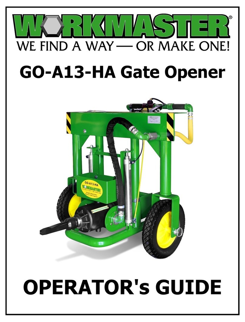
WORKMASTER GO-A13-HA Manual

WORKMASTER
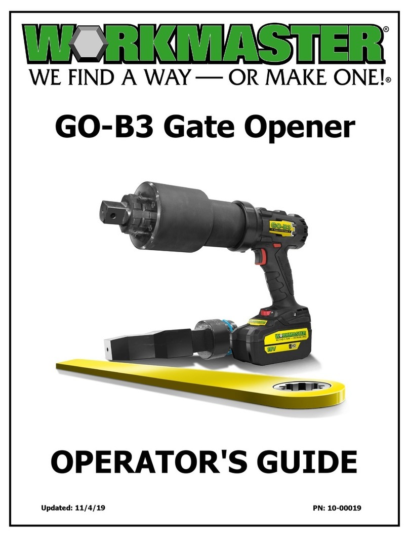
WORKMASTER GO-B3 Manual

WORKMASTER
WORKMASTER GO-A8-PW Manual

WORKMASTER
WORKMASTER GO-A8-PW User manual

WORKMASTER
WORKMASTER GO-A13-HA User manual

WORKMASTER
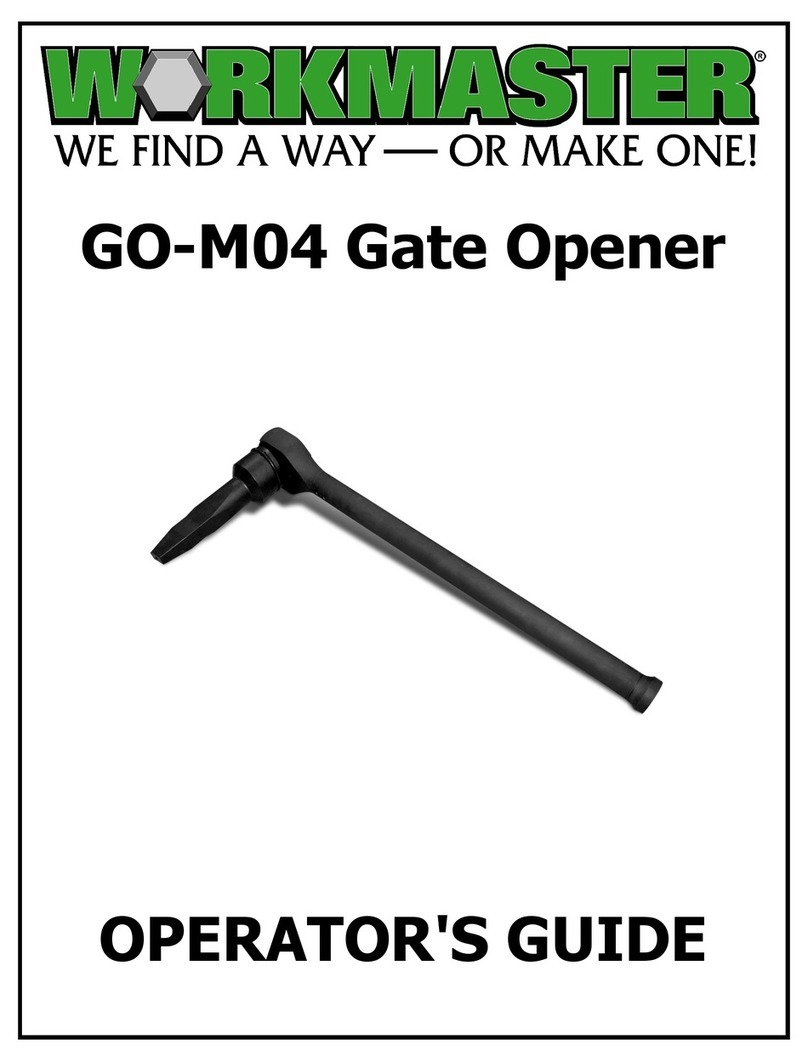
WORKMASTER GO-M04 Manual

WORKMASTER
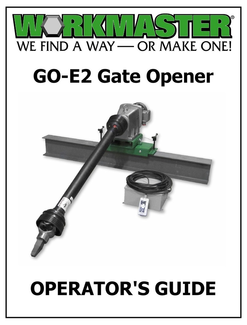
WORKMASTER GO-E2 Manual