WORKMASTER GO-A8-PW Manual

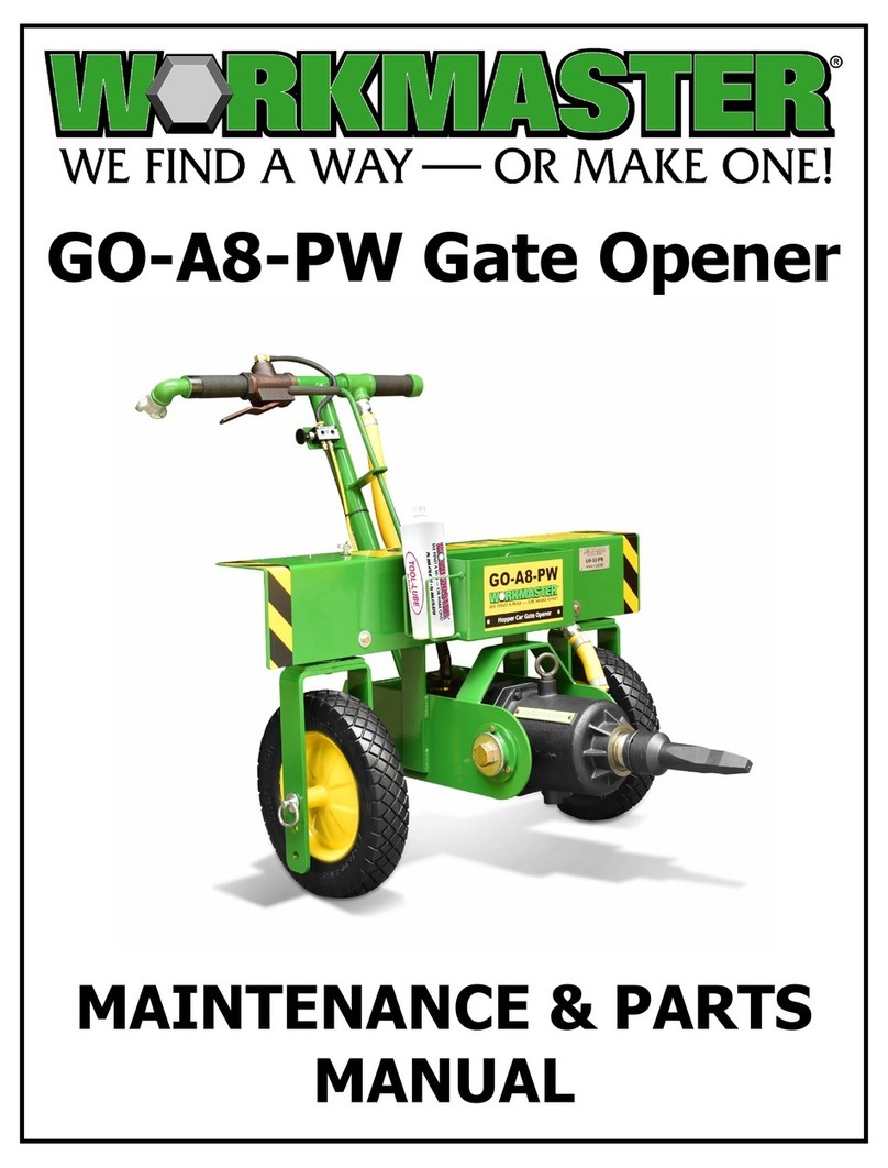
GO-A8-PW Gate Opener
OPERATOR's GUIDE

PH: 866.476.9217
WORKMASTER disclaims any liability for injuries, death or damages arising directly or
indirectly, from the use, operation or application of this product not in accordance with
the procedures, specifications and recommendations contained in this owner’s manual.
The user of this product is responsible to install, maintain and operate the product and
parts or components manufactured or supplied by WORKMASTER in such a manner as
to comply with all federal, state and local rules, ordinances, regulations and laws,
including the Williams-Steiger Occupational Safety Act, and the American National
Standards Institute Safety Code.

PH: 866.476.9217
SYMBOLS
The following symbols are found throughout this Operator's Guide to alert the reader to
the relative danger that may result from non-observance.
This indicates a situation in which a hazard is
imminent and will result in a high probability of serious
injury or death.
This indicates a potentially hazardous situation, which
could result in minor to moderate injury.
CAUTION
This indicates a potentially hazardous situation or
unsafe practice which could result in product or
property damaged.
IMPORTANT
This symbol indicates a general statement to assist the
user in the operation or maintenance of the
equipment.

PH: 866.476.9217
TABLE OF CONTENTS
SECTION PAGE
I. Introduction 1
II. Safety 2
III. Required Materials 2
IV. Specifications and Components 3
V. Air Requirements 9
VI. Pre-Start Check List 10
VII. Compressed Air Treatment 11
VIII. Opening Car Gates 15
IX. Closing Car Gates 18
X. Height Adjustment 20
XI. Storage 21
XII. Accessories 22
Appendix A Troubleshooting A-1
Appendix B Compressed Air System B-1
Appendix C Air Supply Piping C-1

PH: 866.476.9217
LIST OF FIGURES
FIGURE PAGE
Figure 1 Component Layout 4
Figure 2 Forward/Reverse Label 5
Figure 3 Locking Pin Label 7
Figure 4 Pivot Pull Switch Label 8
Figure 5 Filter / Regulator / Lubricator (FRL) Air Control 12
Figure 6 Venturi Section of Lubricator 14
Figure 7 Height Adjustment Label 20
LIST OF TABLES
TABLE PAGE
Table 1 Technical Specifications 3

PH: 866.476.9217 1
I. INTRODUCTION
Fast, safe and economical unloading of covered hopper cars continues to be a problem
at most unloading sites. One of the biggest contributors to this problem is the often
time-consuming and difficult job of opening and closing bottom gates or doors of these
hopper cars. Load compaction, weather conditions, age, abuse, or corrosive or gritty
bulk materials can combine to prevent gate mechanisms from operating smoothly.
Regardless of cause, the costs associated with the problem are significant. Delays in
emptying the hopper cars means slow car turnaround, increased demurrage costs, and
interrupted production schedules. Even more importantly, the chance of worker injury is
high since at many unloading sites, clumsy or dangerous makeshift tools are used
during the “fight” to open a stubborn gate.
To meet our commitment of “WE FIND A WAY – OR MAKE ONE
®
”, WORKMASTER
has developed a line of Hopper Car Gate Openers and accessories which provide a safe,
efficient and economical solution to the problem of opening easy, medium and hard-to-
open hopper car gates.
There are pneumatic, electric and manual units available producing 1,000 to 13,000 ft.
lbs. of torque to eliminate the need for "cheater” bars, sledge hammers, jacks and other
improper tools sometimes used on this difficult job.
This Operation Manual details the specifications, operation, maintenance and safe use
of the GO-A8-PW Pneumatic Hopper Car Gate Opener. Experience has shown that the
GO-A8-PW Opener will open the most difficult car gates. However, the same
experience demonstrates that total satisfaction in use depends on attention to detail in
operating and maintaining the unit.
IMPORTANT
All persons involved in the operation and
maintenance of this equipment should be
thoroughly familiar with the contents of this
manual.
PH: 866.476.9217 2
II. SAFETY
To prevent injury to yourself or others, and/or damage to equipment, you should
adhere to the following basic safety instructions.
1. Read carefully the entire Operator's Guide prior to installing or operating
equipment.
2. Always follow proper precautions and use proper tools and safety equipment.
3. Be sure to receive proper training.
4. Always use the equipment and all its components in applications for which
they are approved.
5. Be sure to assemble all components correctly.
6. Never use worn, defective or damaged components.
7. Practice good housekeeping at all times, and maintain good lighting around
all equipment.
8. Perform Lock-out/Tag-out procedure on all energy sources to the equipment,
mounting structure, loading and discharge systems in accordance with ANSI
Standards before installation or maintenance.
III. REQUIRED MATERIALS
The following items are not supplied with your WORKMASTER Gate Opener but are
necessary for its proper installation and operation.
CLEAN and DRY compressed air capable of supplying 114 CFM @ 85 PSI
High-quality air hose: 1" ID, preferably fitted with a Universal (Chicago
type) coupling.

PH: 866.476.9217 3
IV. SPECIFICATIONS AND COMPONENTS
To operate the GO-A8-PW effectively the user should be familiar with each of the Gate
Opener's components. See Figure 1 for a Component layout, and the separate
WORKMASTER GO-A8-PW Gate Opener Maintenance & Parts Manual
(PN: 10-00067).
The GO-A8-PW Pneumatic Hopper Car Gate Opener consists of a heavy-duty
reversible impact motor, self-closing lever control mechanism and a Rolling Cart. The
GO-A8-PW Opener is portable, rugged and capable of operating in the toughest
environment. Under recommended operating conditions and with regular maintenance,
the GO-A8-PW Opener can generate up to 13,000 ft./lbs. torque. The Impact Motor is
air driven and requires a source of clean, dry compressed air for operation.
Every user should be aware of the technical specifications and operating characteristics
shown below in Table 1.
Table 1: Technical Specifications
CHARACTERISTICS GO-A8-PW
Frame Dimensions 33" x 42" x 45"
Weight 308 Lbs (Shipping 460)
Working Area Required 8 – 10 Ft Minimum – Site Specific
Free Speed 1500 RPM
Working Torque Range 1000 – 13000 Ft-Lbs
CFM/PSI Free Speed 150 @ 85 PSI
CFM/PSI Impacting 114 @ 85 PSI
Air Inlet 1" NPTF
Tire Size 400 x 8 Solid Polyurethane
Anvil Size 1-1/2"
Retainer Type Socket Pin w/ O-Ring
Hose Size 1" ID
Lubrication Air Tool Oil

PH: 866.476.9217 4
Figure 1: Component Layout
(See pg 5 - 8 for details)
1
2
9
7
3
8
11
10
4 6
5

PH: 866.476.9217 5
COMPONENT LAYOUT DESCRIPTIONS
(See Figure 1, pg 4)
1. AIR INLET
The air inlet is a 1" NPT opening with a full-port, Universal (Chicago type)
Coupling. The Coupling supplied is the recommended fitting for the
GO-A8-PW. Replacing the Coupling with a quick-connect type plug will
restrict air flow to the Impactor.
2. FORWARD/REVERSE LEVER (F/R Lever)
The F/R Lever is a steel rod attached to a swivel joint providing a universal
type pivoting action. The rod, painted with enamel, has a rubber, slip-on grip
for control comfort. The F/R Lever controls the direction of rotation of the
Impactor's square drive anvil. A decal located on the Pivot Guard (Item 9)
shows the position for clockwise anvil rotation (3 O'clock position), and for
counterclockwise anvil rotation (11 O'clock position). A label attached to the
Pivot Guard, See Figure 2, shows these handle positions.
Figure 2: Forward/Reverse Label

PH: 866.476.9217 6
3. TOOL BOX
The Tool Box, bolted to the front face of the Pivot Guard, provides easy
access storage for essential GO-A8-PW accessories. When not being used,
the Drive Fitting, Swage Tool and Anvil Extensions should be stored in the
Tool Box, and not on the Impactor's square drive.
4. IMPACTOR
This heavy duty, reversible, pneumatic motor requires a source of clean, dry
compressed air for producing the torque output. For a breakdown showing all
the parts within the Impactor refer to the Maintenance & Parts Manual
(PN: 10-00067). The Impactor can pivot approximately 15 on its
trunnions. For performance ratings, See Table 1 located in the beginning of
this section.
5. WHEEL-AXLE ASSEMBLY
The Wheel-Axle Assembly supports the GO-A8-PW Rolling Cart on wide
stance, flat-free tires, providing excellent balance. The wheels are attached
and secured to the axle by a cotter pin. The Wheel-Axle connects the wheels
to the left and right Height Adjustment Forks. The Forks are welded to a pivot
bar which is actuated by a cylinder via the Pivot Pull Switch (Item 10).
6. HEIGHT ADJUSTMENT FORK
Both Forks are designed to allow the operator to adjust the height of the
Impactor's square drive. By repositioning the Wheel Assembly's Axle into the
holes along the face of each Fork, the Impactor can be raised or lowered up
to 4" to accommodate a variety of unloading site conditions. See Section X:
Height Adjustment for adjustment instructions.
7. OIL CADDY
The Oil Caddy is welded to the Opener's Tool Box and is designed to serve a
dual purpose. Primarily, the Oil Caddy allows the operator to keep a bottle of
air tool oil on-hand at all times; secondly, the Oil Caddy serves as a reminder
to check the oil level in the FRL supplied with this Gate Opener. The oil level
should be checked daily.

PH: 866.476.9217 7
8. PIVOT GUARD
The Pivot Guard protects the pneumatic cylinder which shifts the pivoting
linkage at the cylinder plate forcing the shaft and fork frame to turn at a
predetermined angle. The Pivot Guard has safety lock pinholes that extend
through the pivoting linkage plates and restrict wheel direction change until
the pin is removed. This pivot wheel action allows the GO-A8-PW to travel
with rolling capstans.
9. PIVOT LOCKING PIN
The Pivot Locking Pin is used to lock the wheels and the Height Adjustment
Forks in the straight or pivot position. The Pin, attached to the GO-A8-PW
by a coated lanyard, must be removed before actuating the Pivot Pull Switch.
The Pin should be reinserted into the correct pinhole on the Pivot Guard when
the wheels are in the desired position. A label located on the Pivot Guard, See
Figure 3, shows which pin hole is used to lock the GO-A8-PW's wheels in
the desired position.
Figure 3: Locking Pin Label

PH: 866.476.9217 8
10. PIVOT PULL SWITCH
The Pivot Pull Switch is a pneumatic actuated valve that controls the
movement of the GO-A8-PW's wheels and Height Adjustment Forks. When
the Switch is in the PIVOT position, the wheels will rotate so that they are
parallel to the railcar. When the Pull Switch is in the STRAIGHT position, the
wheels will move perpendicular to the railcar. A label located on the Pivot
Guard, See Figure 4, shows the Pivot Pull Switch position for the desired
wheel movement.
Figure 4: Pivot Pull Switch Label
11. THROTTLE VALVE
The Throttle Valve is a self-closing, lever-operated valve that is attached to
the right hand side of the frame on the Handle Assembly. The Throttle Valve
has a spring loaded lever, which shuts off air to the Impactor as soon as the
throttle is released. Only when the Throttle Lever is depressed will the
Impactor be activated.

PH: 866.476.9217 9
V. AIR REQUIREMENTS
An Air Compressor of sufficient capacity is needed to provide the necessary air volume
(CFM), at the most efficient operating pressure (PSI), to ensure effective and
economical operation of the GO-A8-PW Opener.
1. Air Pressure of 85 to 90 PSI is recommended for maximum performance. This
setting represents required
operating air pressure at the Opener
, not at the
Compressor. There is always a pressure drop between the Compressor and
the Opener; only the pressure and volume at the Opener is effective in doing
work. If the hose is relatively short (25' to 50'), and in good condition, the
pressure drop between the Compressor (or Air Receiver Tank), and the
Opener should not exceed 15% of initial pressure. Adjust Compressor output
to compensate for drop.
2. Clean, moisture-free, lubricated air should be delivered to the Opener at all
times. The air line delivering air to the Opener should be equipped with a
coalescing type filter/dryer to collect and remove moisture and contaminants.
3. Quality air hose designed especially for heavy-duty service should be used. It
should be constructed with an outer covering that resists abrasive wear, an
oil-resistant inner tube, and should be able to withstand temperature
extremes. It should have a working pressure of at least 200PSI.
4. All hose couplings and fittings between the compressor and the Opener
should be full bore type, be in good condition, securely attached, and kept as
tight as possible (check Coupling gaskets). Elimination of air leaks involves
making the air system tight and then keeping it tight. At a typical unloading
site, air losses through bad connections, too many connections and worn
hose often reaches 25% of the total air compressed.
IMPORTANT
Low or inadequate air pressure at the opener is
costly and wasteful. An insufficient air volume
will not allow the GO-A8-PW Opener to operate
effectivel
y
.

PH: 866.476.9217 10
VI. PRE-START CHECK LIST
1. Check FRL Air Control Service Unit: Regulator set at 85-90 PSI; Fill the
Lubricator with the air tool oil supplied. See Section VII: Compressed Air
Treatment for details.
2. With air pressure OFF, install Capstan Drive Fitting making sure that the Pin
Retainer and O-Ring are properly seated.
3. Connect all air hoses and make sure all controls are locked and properly
secured.
4. When using new air hose, blow lubricated air through the hose to completely
coat the inside with oil. This may take up to 10 minutes.
5. Each day, before opening any car gates, operate the GO-A8-PW, free-
speed, for about 5-minutes. This will allow oil to coat the Impactor's internal
components.
Compressed air is an invisible hazard. Any
component through which it passes is capable
of releasing an explosive force which could
result in personal injury or death. As noted
earlier, all persons involved in the operation
and maintenance of this equipment should be
thoroughly familiar with its use.
Be sure all hose connections are tightly
secured. A loose hose not only causes air leaks,
but can whip around and injure personal in the
area. Secure hose couplings with safety pins,
clips, cables or chains.

PH: 866.476.9217 11
VII. COMPRESSED AIR TREATMENT
The GO-A8-PW Hopper Car Gate Opener is designed to operate with a clean, dry air
supply at the required pressure (85 to 90-PSI) and air volume (114 CFM). Dirty and wet
air will result in sluggish operation, more frequent repair and replacement of parts due
to sticking, jamming and rusting of wearing parts. Moisture will also wash out the
required oils, resulting in excessive wear. A decreased air pressure at the Gate Opener
caused by a Regulator Gauge set too low or by restricted (too small) or plugged lines,
valves or couplings will cause a reduction in efficiency at the Gate Opener. Clean, dry
air at the required pressure (85 to 90-PSI) will enable the unloading site worker to start
immediately at an efficient level, with no time lost to purge the lines, drain the Filter,
set the Regulator Gauge or fill the Lubricator, and will help to maintain productivity and
prolong Gate Opener life.
WORKMASTER supplies a heavy-duty, preassembled, high air flow, combination 1"
FRL Service Unit. This Service Unit consists of: a Filter w/ Metal Bowl and Sight Glass; a
Regulator w/ Gauge; and a Lubricator w/ Metal Bowl & Sight Glass (PN: 82-10406) to
treat the compressed air supplied to the Gate Opener. This FRL Service Unit should be
installed as close as practical (the Service Unit should be rigidly mounted in an
activity/weather protected area), to the hopper car unloading site.
The Service Unit is mounted so that the Filter is upstream of the Regulator and
Lubricator. The top of the inlet side of the Filter is clearly marked with an " " for
proper connection from the compressed air system through the Service Unit.
Figure 5: Filter / Regulator / Lubricator (FRL) Air Control

PH: 866.476.9217 12
FILTER: Designed to operate at 250 PSI max pressure and in a temperature range of
40°F to 200°F. Filtering out of dirt and foreign particles, and the separation of moisture
is automatic with air flow. There are no moving parts and no adjustments are
necessary.
Maintenance: Accumulated moisture and sludge must be periodically drained.
Sediment must not be permitted to fill above the Filter's Lower Baffle. The Filter should
be drained weekly by turning the petcock on the bottom of the Filter Bowl
clockwise
½
to 1 turn. This can be done while the Filter is under pressure to take advantage of
blowdown. Periodically, eg, every 3 to 4 months, the Service Unit must be
depressurized so that the Filter can be cleaned to maintain filtering efficiency:
1. Unscrew the Metal Bowl and then unscrew the Filter Element from the Head;
2. Wash the Element in kerosene;
3. Clean the Filter Bowl with soapy water;
4. Inspect the O-ring, replace if damaged or destroyed;
5. Dry the Filter Element thoroughly;
6. Reassemble carefully to avoid stripping and cross threading;
7. After Metal Bowl is tightened, it may be rotated up to 180° for proper viewing of
the Sight Glass.
REGULATOR: Designed to operate at 250 PSI max pressure with an air flow up to 700
CFM and in a temperature range of 40°F to 160°F. The Regulator is always installed
downstream of the Filter but upstream of the Lubricator. Before turning the air supply
to the Service Unit "ON", back-off the Regulator's Pressure Adjusting Knob. When air
supply is turned "ON", regulate the Adjusting Knob until the pressure gauge shows the
desired 85 to 90-PSI. To lock the Adjusting Knob, push down until Knob snaps into
locking groove. To make the Regulator tamper-resistant, remove Adjusting Knob from
the Regulator. The Regulator may be readjusted later by simply replacing the Knob.
Maintenance: Upon detection of leaks, pressure fluctuation, or pressure "creep", the
Regulator must be inspected and cleaned:
1. Depressurize the Service Unit;
2. Remove Bottom Cap;
3. Inspect Valve for damage or wear;
4. Inspect Seat in Head Casting for foreign material or damage;
5. Clean with kerosene and blow-out with air;
6. Replace damaged or worn parts;
7. Replace Bottom Cap.
NB: If leaks persist, it will be necessary to remove Regulator's Bonnet and
inspect Diaphragm and Diaphragm Seat for foreign matter or wear, and
replace if necessary.

PH: 866.476.9217 13
LUBRICATOR: Designed to operate at 250 PSI max pressure and a temperature range
of 40°F to 160°F. This simple, trouble-free design has a large capacity Metal Bowl w/
Sight Glass. It can be filled to the top to extend intervals between filling and the Sight
Glass makes it easy to monitor oil levels. The Lubricator is always installed downstream
of the Filter and the Regulator. It automatically maintains the proper air to oil ratio
regardless of variation in air flow. While the Lubricator must be initially filled while the
Service Unit is not pressurized, the Lubricator can be refilled under pressure by slowly
removing the Filler Plug to release back pressure and then inserting a long spout/funnel
into the opening and adding oil until the Metal Bowl is filled (Sight Glass).
NB: The
Metal Bowl must not be removed while the Service Unit is under air supply
pressure.
NB:
Check the Lubricator's oil level Sight Glass daily, and add Tool-Lube Air
Motor Oil as required.
The Lubricator automatically varies oil mist delivery with air flow variations at any
adjustment. The Lubricator's Wick Element Assembly is factory pre-set at a "mean"
(halfway) adjustment that is appropriate for most Gate Opener applications (distance
between the FRL and the Gate Opener can affect oil mist delivery). If necessary,
increased oil mist delivery can be obtained by raising the Oil Feeder Wick (A) (see
Figure 6) higher in the verturi (air stream). To decrease oil mist delivery, lower the Oil
Feeder Wick into the venturi. Read following instructions if oil mist delivery must be
changed.
The Lubricator for the GO-A8-PW is empty
when shipped from the factory. To avoid
damage to the Impactor the Lubricator must be
filled prior to operation.
IMPORTANT
WORKMASTER's TOOL-LUBE Air Tool Oil is
recommended. It is a High-Grade Air Tool Oil with
absorbing emulsifiers.
Do Not Use
any of the
following: Kerosene, hydraulic fluid, transmission
fluid
,
s
p
indle oil
,
motor oil or antifreeze.
IMPORTANT
For cold weather operation, such as winter
conditions (below 40° F), when the GO-A8-PW is
used outdoors or in an un-heated service area, the
Lubricator should be filled with a Winter Grade Air
Tool Oil
(
PN: 40007
)
.

PH: 866.476.9217 14
Figure 6: Venturi Section of Lubricator
TO ADJUST OIL FEEDER WITH ASSEMBLY (A-C-E)
1. Depressurize Service Unit, then loosen Lubricator's Bowl Ring Nut by hand.
Remove Bowl using Ring Nut. Loosen Locknut (B);
2. Increase oil mist delivery by turning Adjusting Nut (C) up to raise Feeder Wick
with (A) into venturi, or turn Adjusting Nut (C) down to decrease oil mist
delivery;
3. Tighten Locknut (B). The height of the Feeder Wick (A) in the venturi is visually
indicated by the relative position of the Marking Notch (D) on Adjusting Nut (C)
to the bottom of Locknut (B);
4. Reattach Bowl using Ring Nut, be sure O-ring Seal is correctly set in Lubricator
headgroove. Tighten Bowl Ring Nut by hand. (Reassemble carefully to avoid
stripping and cross threading.)
IMPORTANT
For Food Service applications you must use a
high-quality Food Grade Air Tool Oil. Contact
your WORKMASTER Distributor for product
recommendation.

PH: 866.476.9217 15
VIII. OPENING CAR GATES
1. Roll the GO-A8-PW Opener up to the hopper gate until you "rough spot"
position the Opener's output drive with the Railcar Gate's Capstan Socket.
2. Using the CAPSTAN SWAGE TOOL (optional accessory, PN: 33-11120),
clean-out and square-up the Capstan Socket on the Car Gate so that the
CAPSTAN DRIVE FITTING on the Impactor's Output Drive can be aligned
properly, and fully seated in the Railcar Gate's Capstan Socket.
3. Disengage the Car Gate Locking Mechanism before attempting to open the
gate.
4. Roll the Opener forward toward the car gate until the CAPSTAN DRIVE
FITTING is firmly seated in the Railcar's Capstan Socket.
5. Rotate the Forward/Reverse Lever to set the Impactor's motor rotation
direction.
IMPORTANT
Regular use of the CAPSTAN SWAGE TOOL will
ensure a long-life for your Drive Fitting and
your Impactor's Square Drive Anvil. Also, a
clean, square Capstan socket will maximize the
torque transfer between the Opener and the
Car Gate.
CAUTION
Failure to disengage the Car Gate Locking
Mechanism will cause damage to the Car Gate.
Other manuals for GO-A8-PW
2
Table of contents
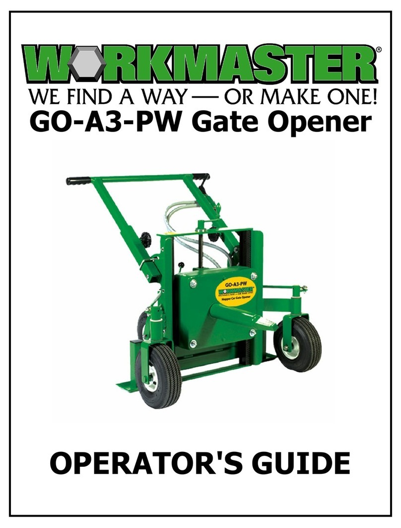
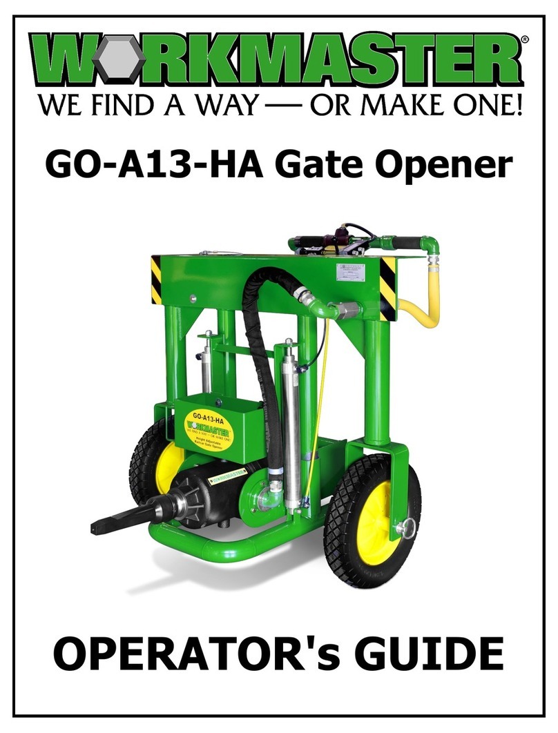
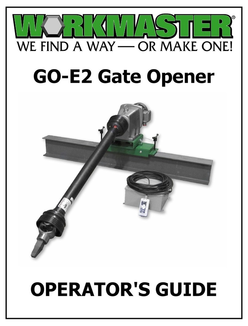
Other WORKMASTER Gate Opener manuals

WORKMASTER
WORKMASTER GO-A8-PW User manual

WORKMASTER
WORKMASTER GO-A3-PW User manual

WORKMASTER
WORKMASTER GO-A13-HA User manual

WORKMASTER
WORKMASTER GO-B3 Manual

WORKMASTER
WORKMASTER GO-M04 Manual

WORKMASTER
WORKMASTER GO-A8-PW Manual

WORKMASTER
WORKMASTER GO-A8-FW User manual

WORKMASTER
WORKMASTER GO-A13-HA Manual

WORKMASTER
WORKMASTER GO-E2 Manual