WorkPro DUO DIM User manual

OUTPUT:
10A/CH.MAX.
FUSE
A B
A
B
Dim/Switch DMX Limit
DMX Address Circuit
Circuit B
DMX
DMX OUT
DMX IN
1=Ground
2=Data-
3=Data+
CAUTION!
Risk of Electric Shock
DO NOT OPEN
Ne pas ouvrir. Risque de choc electrique
Warning: This unit must be grounded
MENU
LOCAL DIM
DIM
(HTP)
Max
Min Max
Min
External
Remote
POWER IN:
AC230V~50Hz, 20A MAX.
FUSE:
F10A 250V 5x20mm.
A B
Circuit A
A
A
B
B
OUTPUT
DUO DIM
Rev 14.04.01
User Manual / Manual de Uso

Features
Thank you for you purchasing the Duo Dim dimmer/Switch pack.
This product includes the following features:
3-pin standard DMX IN/OUT ports providing dimmer information.
Serves as a Switch Pack or Dimmer Pack, depending upon the
current operating mode.
Allows DMX Addressing, Circuit A/B control selection, Local control,
Dim/Switch mode, DMX Limit and END_TRIM.
Providing AC230V, 20A Max. Power line cord with terminal strips conductors.
4 digits Segment Display shows current activity and function state.
On board Local control allows for dim intensity adjustment, from
10%~100% for each individual circuit and complies with HTP
principle(Highest takes precedence).
Two circuits(A&B) hybrid pack with one Schuko socket per circuit.
2 circuit LEDs' indicate relevant circuit activity.
Power failure memory.
Two 10A fuses. One per circuit, 250V, 5x20mm
External remote control function for each individual circuit.
DUO DIM User Manual/Manual de uso Pag. 1

General Instructions
Safe and Efficient Use
Product Care
To prevent fire or shock hazard, do not expose this product to rain or moisture.
In the event of a malfunction(burning smell, etc.), immediately stop operation,
disconnect the power supply plug, and consult authorized service personnel.
No user serviceable parts inside, always consult authorized personnel for
repairs.
Take care not to damage the power cord.
Do not make any inflammable liquids, water or metal objects enter the unit.
This product must be earthed.
Do not dismantle or modify the unit.
Place this unit in a stable location.
Do not use the unit in places subject to excessive humidity, vibration or
bumps.
Unplug the power plug from the sockets when not using the unit for
extended period.
Provide occasional ventilation during use.
This product is intended for indoor use only.
Please read through this operating instructions before installing or using your new
product. After you have finished reading the instructions, put them away in a safe
place for future reference.
DUO DIM User Manual/Manual de uso Pag. 2

1. Overview
1.1 Left Panel
To show the current DMX circuit and function mode-including a DMX signal
indicator. All set up functions are accomplished through the deisplay.
2. 3-pin XLR DMX Input connector:
This input receives DMX signal from a DMX controller or previous device.
3. 3-pin XLR DMX Output connector:
This output feeds DMX signal through to the next DMX device in line.
4. Local Dim(HTP):
To adjust
5. External Remote Jack:
For connecting the remote(Sold separately).
6. Menu Button:
Press this button to scroll through the main menus. The main menus include:
channel lighting intensity and comply with HTP principle(Highest takes
precedence).
14
2
3
5
6
7. Up Arrow Button: Pressing this button will increase any value listed in
the display by one. Pressing and holding this button
down will increase the displayed value quickly.
8. Down Arrow Button: Pressing this button will decrease any value
listed in the display by one. Pressing and holding
this button down will decrease the displayed
value quickly.
9. Circuit LED's (A-B): These LED's display relevant channel intensity & activity.
78
9
1. Segment LED Display:
DUO DIM User Manual/Manual de uso Pag. 3

1. Overview
1.2 Right Panel
8. Schuko Outputs(A-B):
These are two Schuko sockets. Each socket is labeled with "A" and "B". Up
to 10 amps can be connected into each circuit.
9: Power Input:
The line cord supplies the main power to the fixture with the terminal strips.
10:Fuse Holders(A-B):
These two fuse holders house one 10 amp 250v 5x20mm fuse each. Each
circuit fuse protects the corresponding internal components from getting
damaged if there were ever a short or voltage spike.
DUO DIM User Manual/Manual de uso Pag. 4
10
9 8

2. Operation Guide
General Instructions
This is a 2 circuit portable DMX dimmer/switch pack. Each circuit can individually
be set to dim or switch. Using the packs digital display, the pack is quick and easy
to set up. There are two Schuko sockets supplied so more than one par or effect
can be connected to two circuits. The DMX address, Circuit-A&B selection control,
Dim/Switch, DMX Limit and Local Dim are available as well as the remote control
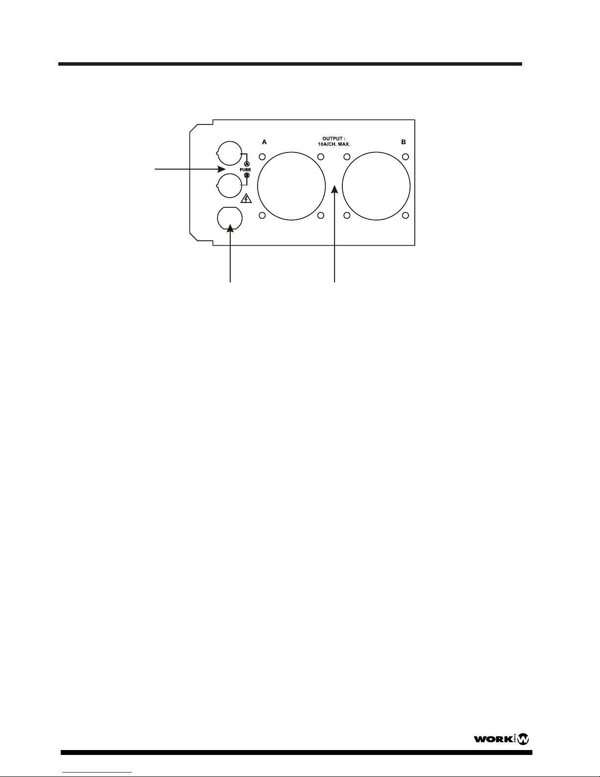
for each individual circuit. Two external circuit fuses allow for quick and easy field
serviceability.
This unit serves as a dimmer pack or a switch pack, depending on operating mode
you've selected.
To optimize performance of this product, please read the instructions carefully to
familiarize yourself with the basic operations.
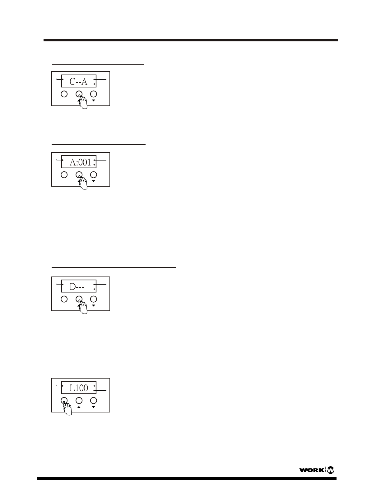
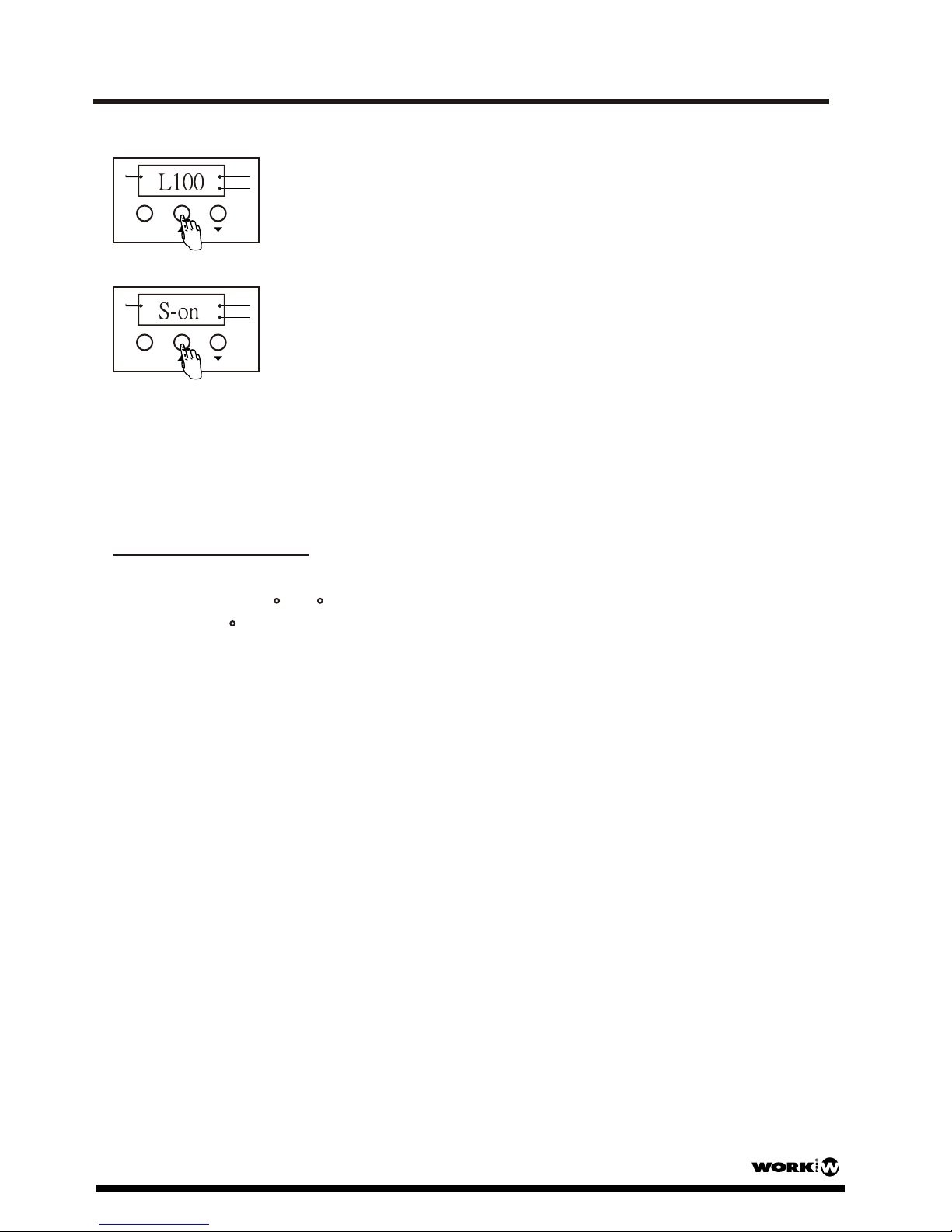
*Note:Abbreviations within the display represent the following: C=Circuit,
A=Address,d=Dimmer & Dim Level, S=Switch on/off, L=DMX Limit.
Press the MENU button to navigate through the menu options. Continually tapping
the MENU button and a combination operation of Up/Down button operation will loop
through the following options.
Quick Operation for Reference
Power Supply:
Before plugging your unit in, be sure the source voltage in your area matches the
required voltage for your Duo Dim power supply. The Duo Dim is only available in a
230v version. Due to variations in line voltage from venue to venue, be sure to plug
your power supply into a wall outlet with matching power before tempting to operate.
With the power failure memory function, this unit can recover the last function state
automatically. If the frequency of power is not stable, the Segment Display will show
"AC-0", please wait until the power is stable.
This unit serves as a dimmer pack or a switch pack, depending on operating mode
you've selected.
DUO DIM User Manual/Manual de uso Pag. 5

2. Operation Guide
Circuit-A/B
Circuit-ADimorSwitch
Circuit-ASwitch Circuit-ASwitchOff
Circuit-ASwitchOn
DMXAddress
Circuit-A Dim Circuit-A DMXLimit
Circuit-BDimorSwitch
Circuit-B Switch Circuit-B SwitchOff
Circuit-B SwitchOn
DMXAddress
Circuit-B Dim Circuit-B DMXLimit
DMX Address Display
Press MENU button Press Up/Down button
Press MENU button
Press MENU button Press Up/Down button
Press MENU button
Press MENU button Press Up/Down button
PressMENUbutton
DUO DIM User Manual/Manual de uso Pag. 6

2. Operation Guide
Circuit A or B Enable
When the power is turned on, this unit enters Circuit A or B
selection mode automatically, and the LED display shows
"C" followed by "A" or "b".
Press the Up/Down button for selecting the desired circuit
to set, a constant light of the desired circuit LED in the
Segment Display indicates its selection.
CircuitB
DMX
MENU
Circuit A
DMX Address Setting
This function allows you to separately set DMX address for
Circuit A or Circuit B.
1. DMX address setting mode enables.
2. The LED display shows "A" or "b" followed by three
numbers(001-512). Use the Up/Down button to select your
desired DMX address.
CircuitB
DMX
MENU
Circuit A
NOTE: If the LED display shows "A" following three numbers, it indicates
the selection of Circuit A, "b" following three numbers for Circuit B.
Dimmer/Switch Pack Enable
CircuitB
DMX
MENU
Circuit A
This function allows you to separately set the output curve of
the unit as one Dimmer Pack or Switch pack.
1. Dimmer/Switch mode enables.
2. The LED display shows "D---" or "S---". Use the Up/Down
button to change between the Dimmer Pack or the Switch
Pack.
3. When the LED display shows "D---", press the MENU
button to enter the DMX Limit function.
NOTE: The LINEAR output enables in the Dimmer Pack Mode and the Non_Dim
output enables in the Switch Pack Mode.
CircuitB
DMX
MENU
Circuit A
DUO DIM User Manual/Manual de uso Pag. 7

2. Operation Guide
4. Use the Up/Down button to select the desired value from
10% to 100%.
5. When the LED display shows "S---", press the MENU
button to enter the Switch on or off setting.
6. And use the Up/Down button to select the Switch on or
Switch off.
CircuitB
DMX
MENU
Circuit A
CircuitB
DMX
MENU
Circuit A
NOTE: In Switch Off mode, the output is controlled by DMX signal
or the encoder adjustment. It c
In Switch On mode, the output is constantly on, DMX signal and the
encoder adjustment are not applicable.
omplies with HTP principle(Highes
takes precedence).
END-TRIM function mode:
The unit offers180 /145 Dimming function mode for user's application. The default
setting is 180 . You should get the authorized personal for help to change the
setting.
END-TRIM Enable
NOTE:
If the function pushbuttons are not used for approximately 20 seconds, the screen
will alternatively display DMX address of two circuits for your.
DUO DIM User Manual/Manual de uso Pag. 8

Technical Specifications
Power Input ........................................................... AC 230V~50Hz, 20 A Max.
Channel Output ...........................................................................10 A/Ch Max.
DMX OUT ................................................................ 3-pin XLR female socket
DMX IN ....................................................................... 3-pin XLR male socket
Fuse ................................................................................. F10A 250V 5x20mm
Dimensions ............................................................................... 300x92x66mm
Weight ................................................................................................... 2.1 Kg
9
Physical Dimensions
9
Front view Side view
Rear view
DUO DIM User Manual/Manual de uso Pag. 9

Características
Puertos DMX IN/OUT 3-pin standard para proporcionar información del dimmer.
Funciona como Switch Pack o Dimmer Pack, dependiendo del modo de
funcionamiento elegido.
Permite direccionamiento DMX A, seleccción de circuito de control
A/B, Control Local , Modo Dim/Switch , DMX Limit y END_TRIM.
Proporciona AC230V, 20A Max. Cable de red con cables pelados
Display de 4 segmentos que muestran la actividad y función presente.
Dos circuitos híbridos (A y B) con un schuko por circuito.
2 circuitos de LEDs' indican la actividad relevante.
Memoria ante fallos de alimentación.
2 fusibles de 10 A. Uno por circuito, 250V, 5x20mm
Función de control remoto externo para cada circuito individual
Gracias por la adquisición del dimmer/Switch pack DUO DIM.
Este producto incluye las siguientes características:
En control Local permite el ajuste de la intensidad del dimmer desde
10% a 100% para cada circuito individual y cumple con el principio
HTP (El mayor toma prioridad)
Este símbolo en su equipo o embalaje, indica que el presente producto
no puede ser tratado como residuos domésticos normales, sino que deben
entregarse en el correspondiente punto de recogida de equipos electrónicos
y eléctricos. Asegurándose de que este producto es desechado
correctamente, Ud. está ayudando a prevenir las consecuencias negativas
para el medio ambiente y la salud humana que podrían derivarse de la
incorrecta manipulación de este producto. EL reciclaje de materiales
ayuda a conservar las reservas naturales. Para recibir más información,
sobre el reciclaje de este producto, contacte con su ayuntamiento, su
punto de recogida más cercano o el distribuidor donde adquirió el producto.
DUO DIM User Manual/Manual de uso Pag. 10

Instrucciones Generales
Uso Seguro y Eficiente
Cuidados del producto
TPara prevenir el riesgo de fuego o descargas eléctrica, no exponga
la unidad a la lluvia o la humedad.
En el caso de mal funcionamiento, deje de usarlo de inmediato,
desconecte el cable de la alimentación y consulte con un servico
técnico autorizado.
No hay elementos de control para el usuario en el interior. Consulte
siempre con personal autorizado para su reparación.
Evite dañar el cable.
Impida que cualquier líquido inflamable, agua u objetos metálicos
entren en la unidad.
Este producto debe ser conectado a tierra.
No desmantele o modifique la unidad.
Sitúe la unidad en un lugar estable.
No use la unidad en lugares sujetos a excesiva humedad, vibración
o golpes.
Desconecte el cable de alimentación si no va a usar la unidad
durante un extenso periodo de tiempo.
Proporcione ventilación ocasional durante su uso.
Este producto la sido concebido para su uso en interior.
DUO DIM User Manual/Manual de uso Pag. 11
Por favor, lea cuidadosamente las instrucciones de uso antes de instalar o usar su nuevo
producto. Después de finalizar su lectura, guardelas en un lugar seguro para futuras
referencias.

14
2
3
5
678
9
1. Vista General
2. 3-pin XLR DMX Input connector:
Esta entrada recibe señal DMX desde un controlador DMX o dispositivo previo
3. 3-pin XLR DMX Output connector:
Esta salida alimenta con señal DMX al siguiente dispositivo DMX de la linea.
4. Local Dim(HTP):
Ajusta la intensidad del canal y cumple con la norma HTP (La mayor tiene
5. Conector para remoto externo:
Para el conexionado de un control remoto (vendido por separado).
6. Tecla Menu:
Presione esta tecla para desplazarse por el menú principal. Este menú incluye:
preferencia).
7. Tecla UP:
8. Tecla Down:
9. LED's (A-B): Estos LEDs muestran el estado del canal en intensidad y actividad
1. Display con segmentos de LEDs:
1.1 Panel Izquierdo
Muestran el circuito DMX actual y el modo de función, incluyendo el indicador
de señal DMX. Todas las configuraciones de función se muestran en pantalla.
Presionando esta tecla se incrementa el valor mostrado en pantalla
en uno. Presionando y manteniendo la tecla, el incremento de valor
es más rápido.
Presionando esta tecla se reduce el valor mostrado en pantalla
en uno. Presionando y manteniendo la tecla, la reducción del
valor es más rápida.
DUO DIM User Manual/Manual de uso Pag. 12

10
9
8. Salidas Schuko (A-B):
9: Entrada de alimentación:
El cable que suministra alimentación a la unidad dispone de terminales pelados.
10:Portafusibles (A-B):
8
1. Vista General
1.2 Panel Derecho
Cada conector schuko está marcado con “A” o “B”. Pueden ser conectada
una carga de hasta 10 A en cada uno de ellos.
Estos dos portafusibles incorporan un fusible de 10 A 250 V 5x20 mm. Cada
uno protege el correspondiente circuito interno de daños causados por
cortocircuitos o sobretensión.
DUO DIM User Manual/Manual de uso Pag. 13

*Nota: Las abreviaturas en pantalla representan lo siguiente: C=Circuit,
A=Address,d=Dimmer & Dim Level, S=Switch on/off, L=DMX Limit.
Alimentación:
2. Guía de Funcionamiento
Instrucciones Generales
La unidad es un dimmer/Switch pack de 2 circuitos portátil. Cada canal puede ser
configurado individualmente como dim o switch. Utilizando la pantalla incorporada
la unidad es fácilmente configurable. Hay dos conectores schuko para el conexionado
de uno o más focos. La dirección DMX, Selección de control de circuito A&B,
Dim/Switch, DMX Limit y Local Dim están disponibles así como de manera remota.
Dos fusibles externos permiten un fácil mantenimiento de la unidad.
La unidad puede ser usada como dimmer pack o switch pack, dependiendo
del modo de uso seleccionado.
Para optimizar el rendimiento de la unidad, por favor, lea estas instrucciones
cuidadosamente para familiarizarse con las operaciones básicas.
Antes de encender la unidad, asegúrese que la alimentación en su área es la
misma que la requerida por su DUO DIM. Estas unidad sólo funciona a 230 V AC.
Debido a las variaciones de red entre lugares de conexión, asegúrese de conectar
la unidad en una toma de alimentación adecuada y con protección de toma de tierra.
Con la función de memoria ante fallos de red, la unidad puede recuperar el último
estado de función de manera automática. Si la frecuencia de red no es estable, la
pantalla mostrará “AC-0”, por favor espere hasta que se estabilice la tensión.
La unidad puede funcionar tanto como Dimmer pack como Switch pack, dependiendo
del modo de funcionamiento elegido.
Funcionamiento rápido
Presione la tecla MENU para navegar a través del menú de opciones. Pulsación
continuada de la tecla MENU en combinación con las teclas Up/Down, le enlazará
con las siguientes opciones.
DUO DIM User Manual/Manual de uso Pag. 14

2. Guía de Funcionamiento
Circuit-A/B
Circuit-ADimorSwitch
Circuit-ASwitch Circuit-ASwitchOff
Circuit-ASwitchOn
DMXAddress
Circuit-A Dim Circuit-A DMXLimit
Circuit-BDimorSwitch
Circuit-B Switch Circuit-B SwitchOff
Circuit-B SwitchOn
DMXAddress
Circuit-B Dim Circuit-B DMXLimit
DMX Address Display
Press MENU button Press Up/Down button
Press MENU button
Press MENU button Press Up/Down button
Press MENU button
Press MENU button Press Up/Down button
PressMENUbutton
DUO DIM User Manual/Manual de uso Pag. 15

2. Guía de Funcionamiento
Habilitar circuito A o B
CircuitB
DMX
MENU
Circuit A
Configurando la dirección DMX
1. Habilite el modo de configuración de direccionamiento DMX.
CircuitB
DMX
MENU
Circuit A
Habilitar Dimmer/Switch Pack
CircuitB
DMX
MENU
Circuit A
CircuitB
DMX
MENU
Circuit A
Al encender la unidad, ésta en el modo de selección de
canal A o B automáticamente y el LED muestra “C” seguido
de “A” o “B”.
Presione las teclas Up·Down para seleccionar el canal deseado
una luz fija se ilumina en el canal seleccionado y es mostrado
en la pantalla
Esta función permite configurar la dirección DMX de cada canal
de manera indivializada para en canal A o B.
2. La pantalla muestra “A” o “B” seguido de tres números (001-512)
Use las teclas Up/Down para seleccionar la dirección deseada.
NOTA: Si la pantalla muestra “A” seguido de tres números, indica que se la
seleccionado el canal A, “B” seguida de 3 números para el canal B.
Esta función permite configurar por separado la curva de
salida de la unidad como un Dimmer pack o Switch pack.
1. Habilite el modo Dimmer/Switch.
2. La pantalla muestra “D---” o “S---”. Use las teclas
Up/Down para cambiar entre ambos modos.
NOTA: La salida Lineal se habilita en el modo Dim y la de disparo en
el modo Switch.
3. Cuando la pantalla muestra “D---”, presione la tecla
MENU para entrar en la función DMX Limit.
DUO DIM User Manual/Manual de uso Pag. 16

CircuitB
DMX
MENU
Circuit A
CircuitB
DMX
MENU
Circuit A
Modo de función END-TRIM :
Habilitar END-TRIM
NOTA:
2. Guía de Funcionamiento
4. Use las teclas Up/Down para seleccionar el valor
deseado entre 10% y 100%.
5. Cuando la pantalla muestra “S---”, presione la tecla
MENU para entrar en la configuración de encender o
apagar el Switch.
6. Use las teclas Up/Down para seleccionar on o off
y encender o apagar el switch.
NOTA: En modo Switch Off, la salida es controlada por la señal
DMX o el ajuste del encoder. Comple con la norma HTP ( el
mayor tiene preferencia).
En modo Swtich on, la salida está constantemente encendida
la señal DMX y el encoder no son aplicables.
La unidad ofrece un modo de función 180º/145º para su uso. La configuración
por defecto es de 180º. Para cambiar esta configuración debe consultar con
personal autorizado.
Si los botones de función no se usan durante unos 20 segundos, la pantalla
mostrará alternativamente la dirección DMX de los dos canales.
DUO DIM User Manual/Manual de uso Pag. 17

Especificaciones Técnicas
Alimentación ........................................................... AC 230V~50Hz, 20 A Max.
Salida de Canal........................................................................10 A/Canal Max.
DMX OUT ................................................................ XLR 3 pines hembra
DMX IN .......................................................................XLR 3 pines macho
Fusible .............................................................................. F10A 250V 5x20mm
Dimensiones ............................................................................. 300x92x66mm
Peso ................................................................................................... 2.1 Kg
Vista Frontal Vista Lateral
Vista Trasera
Dimensiones Físicas
DUO DIM User Manual/Manual de uso Pag. 18

EQUIPSON, S.A.
Avda. El Saler, 14 - Pol. Ind. L´Alteró,46460 - Silla (Valencia) Spain
Tel. +34 96 121 63 01 Fax + 34 96 120 02 42
www.work.es [email protected]
This symbol on the product or on its packaging indicates that this product
shall not be trated as household waste. Instead it shall be handed over to
the applicable collection point for the recycling of electrical an electronic
equipment. By ensuring this product is disposed of correctly, you will help
prevent potential negative consequences for the environment and human
health, which could otherwise be caused by inappropriate waste handling
of this product. The recycling of amterials will help to conserve natural
resources. For more detailed information sabout recycling of this product,
please contact your local city office, your household waste disposal service
or the shop where you purchased the product.
Table of contents
Languages:
Other WorkPro Dimmer manuals