WorkPro MINIDIM 8 User manual

DESCRIPTION
Congratulations with your purchase of this product.
Check for transport damage.
You should be in possession of the following items:
1 MiniDim 8
1 Manual
If you discover transport damage after unpacking the equipment, inform the hauler immediately. Never connect a damaged device. You
BOX CONTENTS
may also contact your supplier.
Output
Oper. temperature -10 C to +50 C
oo
3 A,Max. each one
Power Requirement 12~24VDC, 24 A Max.
Terminal Blocks
MINIDIM 8 incorporates 6 different operating configurations inside DMX mode. These configurations are available using the dip switches 10 to 12. See the closed table.
Connection
1 2 3 4 5 6 7 8 9 10
11 12
DMX starting address
Dip Switch 1 address equals 1
Dip Switch 2 address equals 2
Dip Switch 3 address equals 4
Dip Switch 4 address equals 8
Dip Switch 5 address equals 16
Dip Switch 6 address equals 32
Dip Switch 7 address equals 64
Dip Switch 8 address equals 128
Dip Switch 9 address equals 256
1,2,4
3,4
1,3,4
2,3,4
1,2,3,4
1
2
1,2
3
1,3
2,3
1,2,3
4
1,4
START SWITCHES ON SWITCHES ON
2,4
CH#
START
CH#
1
2
3
4
5
6
7
8
9
10
11
12
13
14
15
..
..
..
..
..
..
ON
OFF
1=
0=
1,2,3,4,5,6,7,8,9
..
For example: Setting DMX address for 21.
Flip switches1,3,&5 to the
"ON"position
Dipswitches# Value
1=1
3=4
5=16
=21
1 2 3 4 5 6 7 8 9 10
11 12
OPERATION GUIDE
1. DMX Control Mode (DMX addressing)
Dimensions
Weight
154(L)x83(W)x28(H)mm
370g
Use the dip switches to set the DMX starting address
MINIDIM 8
MINIDIM 8 is a constant voltage driver for RGB LED devices control. It can operate on several modes: Through DMX signal (with several channel control configurations),
Manual (with intensity adjustment by dip assignation) or Program (3 built-in programs with intensity and speed control). It allows to connect up to 3 A load on its output.
ON
0=OFF
1=
10
ON
0=OFF
1=
11 12
10
11 12
10
11 12
10
11 12
10
11 12
10
11 12
ON
0=OFF
1=
ON
0=OFF
1=
ON
0=OFF
1=
ON
0=OFF
1=
ON
0=OFF
1=
Qty of DMX
Channels
Mode Dip-Switches Function
DMX 8 000 25 Each color on each output can be controlled independently (24 channels) + General Dimmer
DMX 4 001 13 Outputs are grouped in blocks of 2 (OUTPUT 1-2), The colors of each groups are common (12 channels) + General dimmer.
DMX 1 011 4 All Outputs obbey the same color control, it is common in the whole outputs (3 channels) +General Dimmer
DMX C/B 110 2 All outputs obbey to the same control. 1 cannel for color change and another for Bright.
DMX C 111 1 All outputs obbey to the same control. 1 channel for color change.
DMX 8 CH 1: Red OUTPUT 1, CH 2: Green OUTPUT 1, CH 3: Blue OUTPUT 1, CH 4: Red OUTPUT 2 .................. CH 24: Blue OUTPUT 8, CH 25: General dimmer
DMX 4 CH 1: Red OUTPUT 1-2, CH 2: Green OUTPUT 1-2, CH 3: Blue OUTPUT 1-2, CH 4: Red OUTPUT 3-4 ..... CH 12: Blue OUTPUT 7-8, CH 25: General Dimmer
DMX 2 CH 1: Red OUTPUT 1 to 4, CH 2: Green OUTPUT 1 to 4, CH 3: Blue OUTPUT 1 to 4, ..... CH 6: Blue OUTPUT 5 to 8, CH 7: General Dimmer
DMX 1 CH 1: Red OUTPUT 1 to 8, CH 2: Green OUTPUT 1 to 8, CH 3: Blue OUTPUT 1 to 8, CH 4: General Dimmer
DMX C/B CH 1: Color change from Red to White, CH 2: Bright.
DMX C CH 1: Color change from Red to White. Full intensity.
Mode Channels Layout
Channel layout on each mode, assuming that the DMX starting address channel is setup for channel 1. If the starting channel is another, use the table
assigning it by analogy.
DMX 2 010 7 Outputs are grouped in blocks of 4 (OUTPUT 1-4), The colors of each groups are common (6 channels) + General dimmer.
MINIDIM 8 User Manual/Manual de uso Pag 1
MINIDIM 8 can be used in a standard DIN rail using the separate accesories for its fixation.
EN
User Manual
* NOTE: in all DMX mode, the General dimmer channel is the last channel of the configuration, Channel 25, 13, 7, 4 respectivelly
12
ON
0=OFF
1=
NOTE: For a better
understanding. the
square in white color
is considered the switch
in all pictures of this
user manual
MINIDIM 8 incorporates 6 different operation configurations inside DMX mode. These configurations are available through dip-switches numbre 10 to 12. See closed
tables.

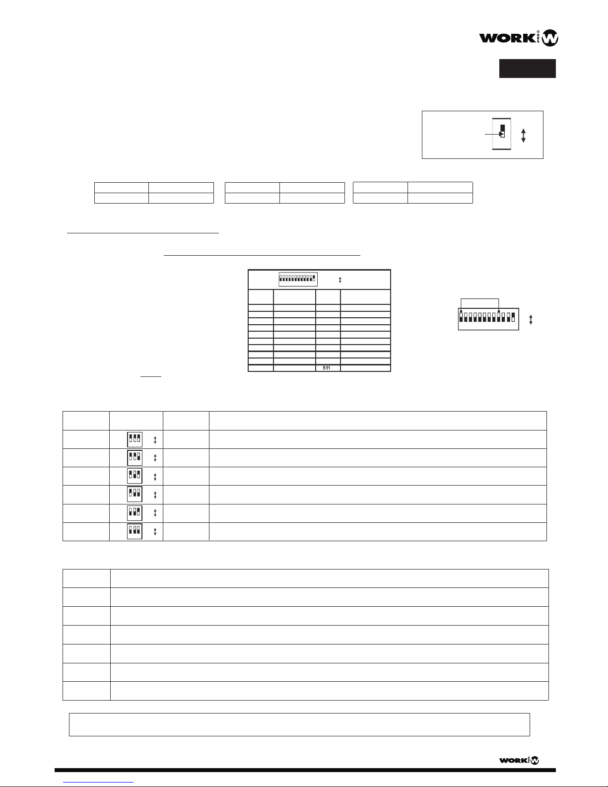
In this mode, the dip-switches 11,12 are flipped to the OFF and 10 to ON.Flip the dip-switch 1~3 to set the intensity of Red LEDs, dip-switch
Green LEDs and dip-switch 7~9 to set the intensity of Blue LEDs. Please refer to the following table for further information.
Red
(SW1~3)
Green
(SW4~6)
Blue
(SW7~9)
Intensity
00157%
10171%
01186%
111100%
001
101
011
111
001
101
011
111
Red
1 2
Green Blue
3 4 5 6 7 8 9 10
ON
0=OFF
1=
11 12
4~6 to set the intensity of
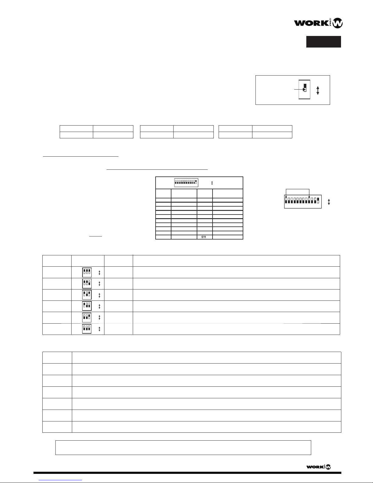
3.Program Mode
In this mode, dip switches 10 & 12 are flipped to ON and dip 11 to OFF. With the dips number 1, 2 and 3, we can select one of three built-in programs. With dips 4, 5 & 6
it is possible to control the general dim level, and using dips 7, 8 & 9, it is possible to control the speed of these programs. See closed tables:
1 2 3 4 5 6 7 8 9 10
11 12
1 2
Num. 1 1 0 0
Num. 3 1 1 0
Num. 2 0 1 0
Program
1 2 3
ON
0= OFF
1=
1 2
0 0 0 0
Intensity
5 64
14% 1 0 0
28% 0 1 0
43% 1 1 0
ON
0= OFF
1=
Intensity
57% 0 0 1
71% 1 0 1
86% 0 1 1
100% 1 1 1
8 97
0 0 0 0
Speed
14% 1 0 0
28% 0 1 0
43% 1 1 0
ON
0= OFF
1=
Speed
57% 0 0 1
71% 1 0 1
86% 0 1 1
100% 1 1 1
Program 1: 7 colors changing without fade: Red, Green, Blue, Red/Green, Red/Blue, Blue/Green, White.
Program 2: Red to Green, Green to Blue, Blue to Red, short transition. With Fade.
Program 3: Red to Green, Green to Blue, Blue to Red, long transition , independent middle colors. With Fade.
Red
(SW1~3)
Green
(SW4~6)
Blue
(SW7~9)
Intensity
0000
10014%
01028%
11043%
000
100
010
110
000
100
010
110
2.Manual Control Mode
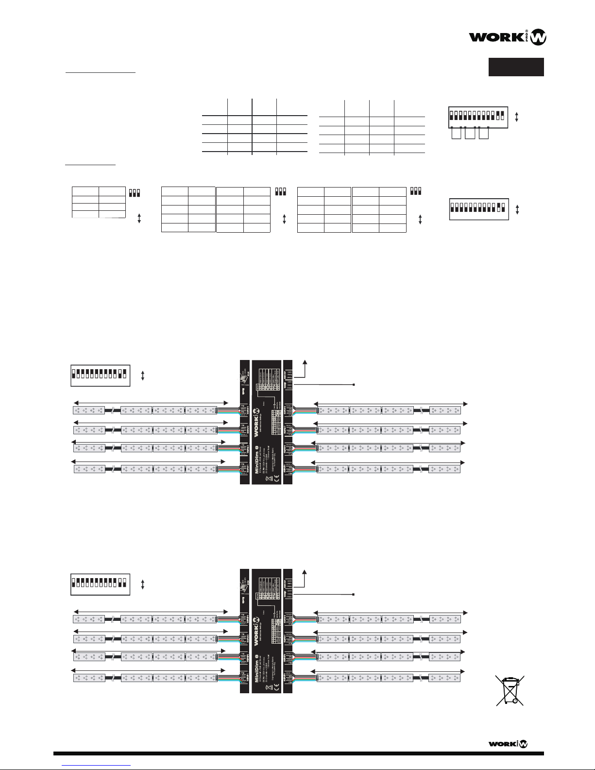
CONNECTING DIAGRAM (EXAMPLES)
A. Installation with DMX control. Setup to DMX 2 MODE ( on Outputs 1, 2, 3 & 4 one channel controls the same color in alll of theses outputs).
In the same way, other 3 independent channels manage the whole color on outputs 5, 6, 7 & 8. Another channel is assigned as General Dimmer.
Each output allows to connect up to 3 A load max.
Up to 3 A max. load (50 x LED LINE 10 max.)
CH 1: Red Outputs 1,2,3,4
CH 2: Green Outputs 1,2,3,4
CH 3: Blue Outputs 1,2,3,4
CH 4: Red Outputs 5,6,7,8
CH 5: Green Outputs 5,6,7,8
CH 6: Blue Outputs 5,6,7,8
CH 7: General Dimmer
1 2 3 4 5 6 7 8 9 10
ON
0=OFF
1=
11 12
Up to 3 A max. load (50 x LED LINE 10 max.)
CH 1: Red Outputs 1,2,3,4,5,6,7,8
CH 2: Green Outputs 1,2,3,4,5,6,7,8
CH 3: Blue Outputs 1,2,3,4,5,6,7,8
CH 4: General Dimmer
1 2 3 4 5 6 7 8 9 10
ON
0=OFF
1=
11 12
B. Installation with DMX control. Setup on DMX 1 MODE ( On all outputs one channel manage the common colors of these outputs), also,another channel is assigned
as General Dimmer. Each output allows to connect up to 3 A load max.
To next DMX control device
From a DMX console
To next DMX control device
From a DMX console
ON
0=OFF
1=
EN
User Manual
MINIDIM 8
MINIDIM 8 User Manual/Manual de uso Pag 2

DMX es un lenguaje universal binario usado para la comunicación entre unidades inteligentes. Cada dipswitch representa un valor binario.
DESCRIPCION
Compruebe si se han producido daños durante el transporte.
La unidad debe contener los siguientes elementos:
1 MiniDim 8
1 Manual
Si descubre daños producidos en la unidad después de desembalarla, consulte con su distribuidor de inmediato y no la conecte.
CONTENIDO
Salida
Temperatura de uso -10 C a +50 C
oo
3A,Max. c.u.
Alimentación 12~24VDC, 24 A Max.
Terminal Blocks
Conexionado
1 2 3 4 5 6 7 8 9 10
ON
0=OFF
1=
11 12
Dirección de inicio DMX
Dip Switch 1 equivale a 1
Dip Switch 2 equivale a 2
Dip Switch 3 equivale a 4
Dip Switch 4 equivale a 8
Dip Switch 5 equivale a 16
Dip Switch 6 equivale a 32
Dip Switch 7 equivale a 64
Dip Switch 8 equivale a 128
Dip Switch 9 equivale a 256
GUIA DE USO
1. Modo de control DMX (Direccionamiento DMX)
Dimensiones
Peso
154(L)x83(An)x28(Al)mm
370g
Use los dip switches para configurar la dirección de inicio DMX
MINIDIM 8
Por ejemplo: Configurar la dirección DMX a 21
Pasar los switch 1,3 y 5 a
la posición "ON"
Dipswitches# Valor
1=1
3=4
5=16
=21
Gracias por la adquisición de este producto.
MINIDIM 8 es un driver de tensión constante para el control de dispositivos LED RGB. Puede funcionar en varios modos: Mediante señal DMX (con varias configuraciones
de canales de control), Manual (Con ajuste de la intensidad por asignación de dips) o Program (3 programas incorporados con ajuste de intensidad y velocidad). Permite
la conexión de hasta 3 A por salida (1 por color) y 24 A como máximo.
MINIDIM 8 puede ser utilizado en un carril standard DIN mediante los accesorios de fijación suministrados opcionalmente.
MINIDIM 8 incorpora 6 configuraciones de funcionamiento diferentes dentro del modo DMX. Estas diferentes configuraciones son accesibles mediante la manipulación de
los dip-switch 10 a 12 como muestra la siguiente tabla adjunta:
10
ON
0=OFF
1=
11 12
10
11 12
10
11 12
10
11 12
10
11 12
10
11 12
ON
0=OFF
1=
ON
0=OFF
1=
ON
0=OFF
1=
ON
0=OFF
1=
ON
0=OFF
1=
Nº de canales
DMX
Modo Dip-Switches Función
DMX 8 000 25 Cada color en cada una de las 8 salidas puede ser controlado independientemente (24 canales) + Intensidad general
DMX 4 001 13 Las salidas se agrupan en bloques de 2 (OUTPUT 1-2), Los colores en ese grupo son comunes (12 canales) + Intensidad general
DMX 2 010 7 Las salidas se agrupan en bloques de 4 (OUTPUT 1-4), Los colores en ese grupo son comunes (6 canales) + Intensidad general
DMX 1 011 4 Todas las salidas obedecen al mismo control de color, el cual es común en todas ellas (3 canales) + Intensidad general
DMX C/B 110 2 Todas las salidas obedecen al mismo control. 1 canal para cambio de color y otro para el brillo.
DMX C 111 1 Todas las salidas obedecen al mismo control. 1 canal para cambio de color.
DMX 8 CH 1: Rojo OUTPUT 1, CH 2: Verde OUTPUT 1, CH 3: Azul OUTPUT 1, CH 4: Rojo OUTPUT 2 .................. CH 24: Azul OUTPUT 8, CH 25: Intensidad General
DMX 4 CH 1: Rojo OUTPUT 1-2, CH 2: Verde OUTPUT 1-2, CH 3: Azul OUTPUT 1-2, CH 4: Rojo OUTPUT 3-4 ..... CH 12: Azul OUTPUT 7-8, CH 25: Intensidad General
DMX 2 CH 1: Rojo OUTPUT 1 a 4, CH 2: Verde OUTPUT 1 a 4, CH 3: Azul OUTPUT 1 a 4, ..... CH 6: Azul OUTPUT 5 a 8, CH 7: Intensidad General
DMX 1 CH 1: Rojo OUTPUT 1 a 8, CH 2: Verde OUTPUT 1 a 8, CH 3: Azul OUTPUT 1 a 8, CH 4: Intensidad General
DMX C/B CH 1: Cambio de color desde Rojo a Blanco, CH 2: Control de Brillo.
DMX C CH 1: Cambio de color desde Rojo a Blanco. Intensidad máxima.
Modo Disposición de canales
Disposición de canales de cada uno de los modos, asumiendo que se ha direccionado la unidad a canal de inicio 1. Si el canal de inicio es otro, utilizar la
tabla asignando los canales por analogía
ES
Manual de uso
* NOTA: En todos los modos DMX, el canal de dimmer general es siempre el último canal de la configuración: Canal 25, 13, 7, 4 respectivamente.
MINIDIM 8 User Manual/Manual de uso Pag 3
1,2,4
3,4
1,3,4
2,3,4
1,2,3,4
1
2
1,2
3
1,3
2,3
1,2,3
4
1,4
CANAL SWITCHES ON SWITCHES ON
2,4
INIC.
CANAL
INIC.
1
2
3
4
5
6
7
8
9
10
11
12
13
14
15
..
..
..
..
..
..
ON
OFF
1=
0=
1,2,3,4,5,6,7,8,9
..
1 2 3 4 5 6 7 8 9 10
11 12
12
ON
0=OFF
1=
NOTA: Para una mejor
comprensión, el
rectángulo en color
blanco se considera
el switch en todos los
dibujos de este manual

2.Modo de Control Manual
(SW1~3) (SW4~6) (SW7~9)
00157%
10171%
01186%
111100%
001
101
011
111
001
101
011
111
Rojo
1 2
Verde Azúl
3 4 5 6 7 8 9 10
ON
0=OFF
1=
11 12
3. Modo Program
1 2 3 4 5 6 7 8 9 10
ON
0=OFF
1=
11 12
1 2
Num. 1 1 0 0
Num. 3 1 1 0
Num. 2 0 1 0
Programa
1 2 3
ON
0= OFF
1=
1 2
0 0 0 0
Intensidad
5 64
14% 1 0 0
28% 0 1 0
43% 1 1 0
ON
0= OFF
1=
Intensidad
57% 0 0 1
71% 1 0 1
86% 0 1 1
100% 1 1 1
8 97
0 0 0 0
Velocidad
14% 1 0 0
28% 0 1 0
43% 1 1 0
ON
0= OFF
1=
Velocidad
57% 0 0 1
71% 1 0 1
86% 0 1 1
100% 1 1 1
Programa 1: 7 colores cambiando sin fade: Rojo, Verde, Azul, Rojo/Verde, Rojo/Azul, Azul/Verde, Blanco.
Programa 2: Rojo a Verde, Verde a Azul, Azul a Rojo. Transición corta. Con Fade.
Programa 3: Rojo a Verde, Verde a Azul, Azul a Rojo. Transición larga. Colores medios independientes. Con Fade.
Rojo
(SW1~3)
Verde
(SW4~6)
Azúl
(SW7~9)
Intensidad
0000
10014%
01028%
11043%
000
100
010
110
000
100
010
110
DIAGRAMA DE CONEXIONADO (EJEMPLOS)
A. Instalación con control DMX. Configurado en MODO DMX 2 (Las salidas 1, 2, 3 y 4 están configuradas para que un canal controle los colores comunes en esas salidas.
De igual forma, otros 3 canales independientes manejan la totalidad de colores de las salidas 5, 6, 7 y 8. Un canal se asigna como nivel de dimmer general.
Cada salida permite el conexionado de hasta 3 A de carga total.
En este modo los dip switches 11 y 12 se configuran a OFF y el 10 a ON. Utilice los dip 1-3 para configurar la intensidad del los LEDs Rojos, los dip 4-6 para configurar
la intensidad de los LEDs Verdes, y los dip 7-9 para configurar la intensidad de los LEDs Azules. Compruebe la tabla adjunta para más información.
Rojo
Verde Azúl
Intensidad
En este modo, los dip 10 y 12 se configuran en ON y el dip 11 a OFF. on los dip 1-3, se selecciona uno de los 5 programas incorporados. Con los dip 4-6, es posible
controlar el nivel de dimmerización general, y usando los dip 7-9, es posible controlar la velocidad de los programas. Ver tabla adjunta.
Hasta 3 A de carga max. (50 x LED LINE 10 max.)
CH 1: Rojo Salidas 1,2,3,4
CH 2: Verde Salidas 1,2,3,4
CH 3: Azul Salidas 1,2,3,4
CH 4: Rojo Salidas 5,6,7,8
CH 5: Verde Salidas 5,6,7,8
CH 6: Azul Salidas 5,6,7,8
CH 7: Dimmer general
1 2 3 4 5 6 7 8 9 10
ON
0=OFF
1=
11 12
Hasta 3 A de carga max. (50 x LED LINE 10 max.)
CH 1: Rojo Salidas 1,2,3,4,5,6,7,8
CH 2: Verde Salidas 1,2,3,4,5,6,7,8
CH 3: Azul Salidas 1,2,3,4,5,6,7,8
CH 4: Dimmer general
1 2 3 4 5 6 7 8 9 10
ON
0=OFF
1=
11 12
B. Instalación con control DMX. Configurado en MODO DMX 1 (Todas salidas están configuradas para que un canal controle los colores comunes en esas salidas).
Además, un canal se asigna como nivel de dimmer general. Cada salida permite el conexionado de hasta 3 A de carga total.
Al siguiente dispositivo de control DMX
Desde una consola DMX
Al siguiente dispositivo de control DMX
Desde una consola DMX
ES
Manual de uso
MINIDIM 8
MINIDIM 8 User Manual/Manual de uso Pag 4
Table of contents
Languages:
Other WorkPro Dimmer manuals
Popular Dimmer manuals by other brands

Efapel
Efapel 40215 instructions

Lapetek
Lapetek SMART 300 Assembling instructions

Sunricher
Sunricher SR-2303DIN quick start guide

ETC
ETC SMARTRACK user manual

Schaudt
Schaudt LIS 101 Operation and assembly instructions

elsner elektronik
elsner elektronik RF-L UN-ST Technical specifications and installation instructions