Worldwel Longrun 500LTP User manual

INVERTER DC TIG ARC WELD ING MACHINE
500LTP
OPERATION MANUAL
DO NOT INSTALL, OPERATE OR MAINTAIN THIS MACHINE WITHOUT READING THIS
MANUAL AND PLEASE ALWAYS THINK BEFORE YOU ACT.
www.worldwel.com

TECHNICAL SPECIFICATIONS■
- SUFFICIENT CAPACITY of main transformer by self-manufacturing
- ELECTRIC SHOCK PROTECTOR reduces No load voltage to 14VDC for user safety when welder is
not in use.
-Easy to verify welding current during welding by DIGITAL AMMETER.
-Optional REMOTE CONTROL BOX is available for adjusting output current without going back to
power source.
ITEM UNIT SPECIFICATION
Rated Input Voltage V
220/380/440, 50/60Hz
3 Phase
Process ― TIG STICK
Rated Output Current A 500 300
Input Capacity 380V kva 21 15
No Load Voltage V 62 (380V)
Output Current Range A 15~500 20~340
Output Voltage @ rated output V 30 33.6
Duty Cycle @ rated output % 60
Dimension (W×D×H) mm 385 × 765 × 610
Weight kg 54
Crater Current Range A 15 ~ 500
Start Current Range A 15 ~ 500
Pulse Current Range A 10 ~ 500
Pulse Width Range % 0 ~ 100
Pulse Frequency Range Hz 0.5 ~ 500
Up slope Time Range sec
0.1 ~ 5
Down slope Time Range sec
Gas After Flow sec 0.5 ~ 25
Cooling Method ― Air cooling / Water cooling

General Safe Practices
Wear approved safety glasses with side shields under your welding helmet or face shield and at all■
times in the work area.
When working above floor level, use a safety belt to protect yourself from a fall should you get a■
shock.
Do not install or place machine on or over combustible surfaces.■
Be sure that all installation, operation, maintenance and repair procedures are performed only by■
qualified persons.
Electric shock can kill.
Wear Dry, hole-free insulating gloves and body protection. Do not touch electrode with bare hand.■
Do not wear wet or damaged gloves.
Do not touch live electrical parts.■
Never dip the electrode in water for cooling.■
Properly install and ground all equipment.■
Protect yourself from electric shock by insulating yourself from work and ground. Use■
non-flammable, dry insulating material if possible, or use dry rubber mats, dry wood or plywood,
or other dry insulating material big enough to cover your full area of contact with the work or
ground, and watch for fire.
Turn off input power using the disconnect switch at the fuse box before working on the equipment.■
Frequently inspect input power cord for damage or bare wiring and repair or replace cord■
immediately if damaged.
Fumes and gases can be dangerous.
Welding may produce fumes and gases hazardous to health. Avoid breathing these fumes and■
gases. When welding, keep your head out of the fume. Use enough ventilation and/or exhaust at
the arc to keep fumes and gases away from the breathing zone.
Use enough forced ventilation or local exhaust (forced suction) at the arc to remove the fumes■
from your breathing area.
Use a ventilating fan to remove the fumes from the breathing zone and welding area.■
Arc rays can burn eyes and skin.
Use welding helmet with correct shade of filter to protect your eyes from sparks and the rays of the■
arc.
Wear welders cap and safety glasses with side shields. Use ear protection when welding out of■
position or in confined spaces. Button shirt collar.
Wear complete body protection. Wear oil-free protective clothing such as leather gloves, heavy■
shirt, cuffless pants and high boots.
Welding sparks can cause fire or explosion.
Remove fire hazards from the welding area. If this is not possible, cover them to prevent the■
welding sparks from starting a fire. Remember that welding sparks and hot materials from welding
can easily go through small cracks and opening to adjacent areas. Avoid welding near hydraulic
lines.
When not welding, make certain no part of the electrode circuit is touching the work or ground.■

Accidental contact can cause overheating and create a fire hazard.
Do not weld on drums, tanks, or any closed containers unless a qualified person has tested it and■
declared it or prepared it to be safe.
Connect the work cable to the work as close to the welding area as practical. Work cables■
connected to the building framework or other locations away from the welding area increase the
possibility of the welding current passing through lifting chains, crane cables or other alternate
circuits. This can create fire hazards or overheat lifting chains or cables until they fail.
INSTALLATION■
The welding machine shall be installed at a place ;●
free from the inflammables․
less humidity, dirt and dust․
protecting from influence of direct sunlight, wind and rain․
not generated oil vapor and corrosive gas․
operating temperature range is from -10 to 40℃ ℃․
least 30 away from wall and other welding machine㎝․
Input Connection (Rear of the machine)●
Be sure the voltage, phase and frequency of the input power is as specified on the name plate
located on the rear panel of the machine.
To connect the power cables, turn the power switch OFF․
Verify the voltage to be supplied from main power.․
Open the cover of terminal plate and connect the power cable to the power input terminal on the rear․
of the machine and close the cover of terminal plate.
If the input power is single phase, connect two cables on left and right terminal without center.√
For grounding the machine, connect a ground wire to the ground terminal marked with the symbol is․
located on the rear panel of the machine.
Connect the gas hose to the gas input terminal.․
If you want to connect the water cooling unit, connect the water hose to WATER IN terminal.․

Input voltage selection※
220V 380V 440V
Output Connection (Front of the machine)●
Connect the work cable (which is connected to the work clamp) to the METAL terminal.․
To connect the TIG torch, connect a electrode cable to the TORCH terminal and a torch switch․
connector to the torch switch receptacle and a gas connector to the output gas receptacle.
If you want to connect the remote controller, connect the connector of remote controller to REMOTE․
CONTROL terminal.
If the water cooling unit is installed, connect the water input hose of water cooled torch to WATER OUT․
terminal of welder.
․Verify the connection of voltage selection terminal.
If necessary to change it,√
Remove the cover of input voltage selection plate.․
Position the wires for the voltage to be supplied from main power.․
For 380V and 440V input, position a switch for the voltage would be used which is rear.․

Output connection for stick welding●
Connect the work cable (which is connected to the work clamp) to the TORCH terminal.․
Connect the electrode cable (which is connected to the electrode holder) to the METAL terminal.․
FRONT PANEL■

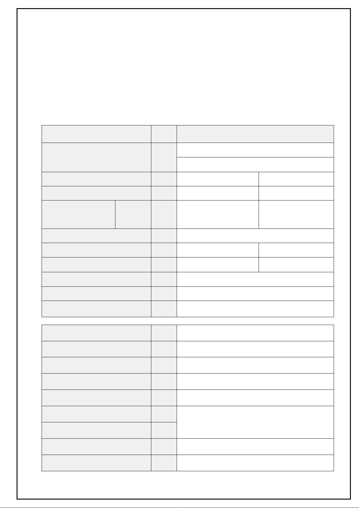
1Power Switch When it is turn on, the cooling fan and all of electrical circuit inside the
machine will be operated.
2Ammeter Displays the welding current
3Power Lamp It indicates that the machine is on and input voltage is within acceptable
range.
4Ready Lamp It indicates that the machine is ready to run. If the warning lamp is turn
on, then it will be off.
5Warning Lamp
It indicates the thermal over load or output disabled by any electrical
problems or the water pressure. When it is on, the machine will not
supply power at the output.
- If over-heating occurs, it will blinking on until the machine has
sufficiently cooled by cooling fan or water.
- If the output is disabled by any electrical problems or the insufficiency
of water supply pressure, it will stay on.
6Water Lamp If selected the water cooling, it is turn on by the insufficiency of water
supply pressure.
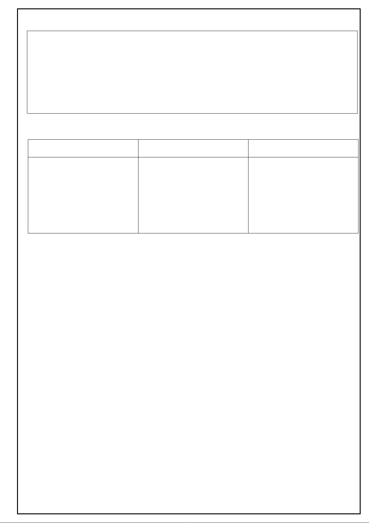
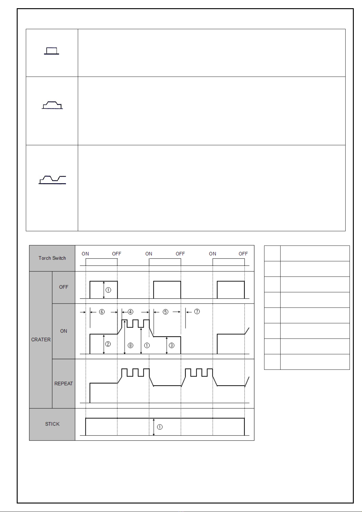
7Welding Mode Selector It has four welding modes - Crater Off, Crater On, Crater Repeat and
Stick.
8Welding Current Control Adjust the welding current
9Pulse Current Control Adjust the pulse current
10 Start Current Control Adjust the start current
11 Up slope Time Control It controls the time to reach to the welding current from the start
current.
12 Gas Check Switch It is for checking the flow of the gas. If this switch is ON, then the gas is
flowed by opening the solenoid valve inside the machine.
13 Pulse Width Control It controls the pulse width
14 Pulse Frequency Control
It controls the pulse frequency. If the low pulse selected at the pulse
frequency selection switch, apply the inside circle 0.5-25Hz or if the high
pulse selected, apply the outside circle 10-500Hz.
15 Pulse Frequency selection switch
It choose the pulsed TIG (Low pulse, High pulse) or non pulsed TIG.
When compared with non pulsed TIG welding performed at the same
average current, the pulsed TIG get better results smaller heat affected
zone, fewer deformations and reduced chance of cracking and gas
entrapment.
16 Crater current control It controls the crater current. It is important to get the good welding
quality.
17 Down slope time control
It controls the time to reach to the crater current from the welding
current. It is important to carefully control the downslope of current to
get the good welding bead.
18 Cooling mode selection switch It choose the cooling mode "WATER COOL" or "AIR COOL"
19 Gas after flow time control
The output current of the machine will turn OFF and then the gas valve
will remain open to continue the flow of the gas. It adjusts the duration
of this after-flow time.

Start Up■
Stick Welding TIG Welding
Turn On the main power supplied to welder Turn On the main power supplied to welder
Select "STICK" from the welding mode selector Select "WATER COOL" or "AIR COOL" from the
Cooling mode selection switch
Connect the remote controller to "REMOTE
CONTROL" terminal if necessary
Select Crater Off or Crater On or Crater Repeat
from welding mode selector
Turn On the power switch of welder, and then
verify that the power lamp and ready lamp are On
and the cooling fan is running
Adjust properly the pulse frequency, pulse
width, start current, crater current, up slope
time, downslope time, gas after-flow time
Start to weld with adjusting the proper welding
current
Connect the remote controller to "REMOTE
CONTROL" terminal if necessary
Open the valve of gas tank
Turn On the power switch of welder, and then
verify that the power lamp and ready lamp are
On and the cooling fan is running
Regulate the gas flowed with pressing the torch
switch
Start to weld with adjusting the proper welding
current and crater current

Welding Mode■
Crater Off
Press and hold the torch switch, the machine will open the gas valve to start the flow of the
shielding gas during the pre-flow time and then the arc is started at welding current. When
finish to weld, release the torch switch, then the arc is off and flow the gas during the gas
after-flow time.
Crater On
Press and hold the torch switch, the machine will open the gas valve to start the flow of the
shielding gas during the pre-flow time and the arc is started at the crater current. At this time
release the torch switch, the output current will be increased from the crater current to the
welding current during the up slope time. When finish to weld, press and hold the torch switch,
the output current will be decreased from the welding current to the crater current during the
down slope time. At this time release the torch switch, the arc is off and flow the gas during the
after-flow time.
Crater Repeat
Press and hold the torch switch, the machine will open the gas valve to start the flow of the
shielding gas during the pre-flow time and the arc is started at the crater current. At this time
release the torch switch, the output current will be increased from the crater current to the
welding current during the up slope time. At this time Press and hold the torch switch, the
output current will be decreased to crater current and then release the torch switch, the output
current will be increased to welding current. When finish to weld, press and hold the torch
switch, the output current will be decreased from the welding current to the crater current during
the down slope time. At this time just release the torch from the metal to be welded and then
the arc is off and flow the gas during the after-flow time.
①Welding current
②Start current
③Crater current
④Up slope time
⑤Down slope time
⑥Gas pre-flow time
⑦Gas after-flow time
⑧Pulse current

TROUBLESHOOTING■
If all recommended action have been checked and the problem persists, please contact our√
service center
SYMPTOMS REASON RECOMMENDED ACTION
Cooling fan does not run when the power switch is
turn on.
No input voltage․
Fuse (3A) is blown․
Power switch broke down․
Cooling fan broke down․
Verify input voltage․
Replace Fuse (3A)․
Replace Power switch․
Replace Cooling fan․
Gas does not
flow from torch
Gas does not flow from torch
when the GAS CHECK switch is
"CHECK" position
Close the valve of gas tank․
Gas check switch broke down․
Open the valve of gas tank․
Replace Gas check switch․
Gas does not flow from torch
when pressing the torch switch
Torch switch connector does not․
connect perfectly
Torch switch broke down․
Control PCB broke down․
Reconnect Torch switch connector․
Replace Torch․
Replace Control PCB․
Gas flows continuous at "Off" position of GAS CHECK
switch
GAS CHECK switch broke down․
Torch broke down․
Control PCB broke down․
Replace GAS CHECK switch․
Replace Torch․
Replace Control PCB․
It does not adjust the welding current and crater
current on the remote controller
Remote control connectors of․
remote controller does not
connect perfectly
Volume broke down․
Control PCB broke down․
Reconnect Remote control․
connectors of remote controller
Replace Volume․
Replace Control PCB․
Arc does not started
Torch cable is broke․
Torch switch connector does not․
connect perfectly
Work cable does not connect․
perfectly
Torch broke down․
Control PCB broke down․
Repair Torch cable․
Reconnect Torch switch connector․
Reconnect Work cable․
Replace Torch․
Replace Control PCB․
Crater does not work Crater select switch broke down․
Control PCB broke down․
․Contact our service center


500LTP PARTS LIST
*Description can be changed by LOT number
NO. PART NAME DESCRIPTION QTY.
1 Control Transformer 9645 1
2 Control Transformer 4114 1
3 Main PCB WNLT-01 1
4 HF PCB TMD-45A89 1
5 Control Transformer PCB VAC-02 1
6 PWM PCB WAPD-01 1
7 Relay HR710-2PB DC24V 1
8 MF Condenser 20 /800V㎌ 4
9 MF Condenser 10 /800V㎌ 2
10 Condenser 2700UF/400V 2
11 Input Terminal 6M/M 1
12 NFB 3P-80A NDB3-100J4 80/3LTS 1
13 Front PCB VR-S/W BOARD 1
14 META PCB META V1 1
15 FUSE 5A 1
16 VOLUME RV24YN, 500K 1
17 FAN 120T 2
18 FAN 150T 1
19 Cap Switch SZW26-63/D344.424 1
20 Input Diode 6RI 100E-080 2
21 IGBT 200A/600V 2
22 IGBT Drive PCB WGE-01 2
23 TIG IGBT Snubber WSB-01 1
24 Temp. Switch N85 1
25 Pressure Sensor DP-07 1
26 Solenoid Valve DC24V, 3.0Φ 1
27 Output Diode 300A/600V 2
28 Resistor, Discharge 20W10Φ 2
29 Terminal, MID MID 2
30 Connector K25-2R 2
31 Nipple 9/16*One touch 6Φ 2
32 Nipple 9/16*1/4 2
33 Noise Filter PCB WTF-02 1
34 Pilot Surge PCB WNF-01 1
35 Remote PCB WRM-01 1
36 Induction coil 500LTP 1
37 Choke Transformer 500LTP 1
38 Main Transformer 500LTP 1

Thank you very much for choosing our machine
Please record your machine identification information below for future reference. This
information can be found on the nameplate of your machine.
Product Name INVERTER DC TIG ARC WELDER
Model Number LONGRUN 500LTP
Date Manufactured
Serial Number
Date Purchased
Where Purchased
Where you use
Whenever you request replacement parts or information on this machine, always
supply the information you have recorded above. The date number is especially
important when identifying the correct replacement parts.
Complete this form, please fax it to our selling agency in your country or us for
warranty statement.
WORLDWEL CO., LTD.
11-101, Songlim-dong, Dong-gu, Incheon-city, Korea
TEL : +82-32-876-2114 FAX : +82-32-876-2117
www.worldwel.com
Table of contents
Other Worldwel Welding System manuals

Worldwel
Worldwel longrun 350LA User manual

Worldwel
Worldwel 350LC2 User manual

Worldwel
Worldwel Longrun 500LMP User manual

Worldwel
Worldwel LONGRUN 500LT3 User manual

Worldwel
Worldwel Longrun 600LC User manual

Worldwel
Worldwel Longrun LD Series User manual

Worldwel
Worldwel LONGRUN 1500WG User manual

Worldwel
Worldwel longrun 350SLC User manual
Popular Welding System manuals by other brands

Elettro C.F.
Elettro C.F. TIG 118 instruction manual

Elettro C.F.
Elettro C.F. Plasma 420 instruction manual

Alfain
Alfain PEGAS 200 AC/DC PULSE Smart operating manual

Alfain
Alfain PEGAS 41 PLASMA PFC operating manual

Uni-Mig
Uni-Mig KUMJRRW140 operating manual

FRONIUS
FRONIUS ActiveCharger 1000 Operating instructions & parts list