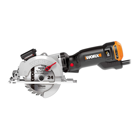
Worx WX420 User manual

WX420
Mini circular saw EN
Minihandkreissäge D
Mini scie circulaire F
Mini sega circolare I
Mini-sierra circular ES
Mini-cirkelzaag NL
Mini pilarka tarczowa PL
HU
RO
CZ
SK
P06
P17
P29
P41
P53
P65
P77
P89
P101
P113
P125

Original instructions EN
Originalbetriebsanleitung D
Notice originale F
Istruzioni originali I
Manual original ES
Oorspronkelijke gebruiksaanwijzing NL
Tłumaczenie oryginalnych instrukcji PL
Eredeti használati utasítás HU
RO
CZ
SK

4
3
6
910
11
13
14
15
16
2
23 1
8
12
7
5

17 183
19
20
21
85
(4) (3)
6
1
17 183
10
4
AB1 B2
CDE
F1 F2 G
H1 H2 I

22
J1 J2 J3
J4 J5 J6
KLM
N
16

Mini circular saw EN
6
1. ON/OFF SWITCH
2. SOFT GRIP HANDLE
3. LARGE L SPANNER/ALLEN KEY
4. SMALL L SPANNER/ALLEN KEY
5. LASER ON-OFF SWITCH
6. LOCK OFF SWITCH
7. DUST EXTRACTION OUTLET
8. DEPTH OF CUT ADJUSTMENT AND LOCK LEVER
9. BASE PLATE
10. SAW BLADE
11. PARALLEL GUIDE FIXTURE
12. BLADE ALIGNMENT INDICATOR
13. PARALLEL GUIDE CLAMPING SCREW
14. PROTECTIVE BLADE GUARD
15. LASER GUIDE
16. BATTERY STORAGE COVER
17. SPINDLE CLAMPING SCREW (See Fig. C)
18. BLADE CLAMPING WASHER (See Fig. C)
19. PARALLEL GUIDE (See Fig. D)
20. VACUUM ADAPTER (See Fig. E)
21. PLASTIC BASE PLATE COVER (See Fig. F1)
22. LASER BATTERIES (TWO) (See Fig. J3)
23. DEPTH OF CUT INDICATOR
* Not all the accessories illustrated or described are included in standard delivery.

Mini circular saw EN
7
TECHNICAL DATA
Type WX420 (4-designation of machinery, representative of Saw)
Voltage 230-240V~50Hz
Power input 400W
No load speed 3500/min
Blade size 85mmx15mm
Max cutting depth 27mm
Laser battery model no. LR44 1.5V
Protection class /ll
Machine weight 1.5kg
NOISE INFORMATION
A weighted sound pressure LpA: 80dB(A)
A weighted sound power LwA: 91dB(A)
KPA& KWA 3.0dB(A)
Wear ear protection when sound pressure is over 80dB(A)
VIBRATION INFORMATION
Vibration total values (triax vector sum) determined according to EN 60745:
Typical weighted vibration Vibration emission value ah= 4.24m/s2
Uncertainty K = 1.5m/s²
WARNING: The vibration emission value during actual use of the power tool can differ
from the declared value depending on the ways in which the tool is used dependant on
the following examples and other variations on how the tool is used:
How the tool is used and the materials being cut or drilled.
The tool being in good condition and well maintained.
The use the correct accessory for the tool and ensuring it is sharp and in good condition.
The tightness of the grip on the handles and if any anti vibration accessories are used.
And the tool is being used as intended by its design and these instructions.
This tool may cause hand-arm vibration syndrome if its use is not adequately
managed.

Mini circular saw EN
8
WARNING: To be accurate, an estimation of exposure level in the actual conditions of
use should also take account of all parts of the operating cycle such as the times when
the tool is switched off and when it is running idle but not actually doing the job.This may
significantly reduce the exposure level over the total working period.
Helping to minimise your vibration exposure risk.
ALWAYS use sharp chisels, drills and blades.
Maintain this tool in accordance with these instructions and keep well lubricated (where
appropriate).
If the tool is to be used regularly then invest in anti vibration accessories.
Avoid using tools in temperatures of 100C or less
Plan your work schedule to spread any high vibration tool use across a number of days.
ACCESSORIES
TCT 24T blade 1
Diamond disc 1
HSS 44T blade 1
V base 1
Parallel guide 1
Vacuum adaptor 1
Plastic base plate cover 1
L spanners/allen keys 2
We recommend that you purchase your accessories from the same store that sold you the tool.
Use good quality accessories with a well-known brand name. Choose the type according to
the work you intend to undertake. Refer to the accessory packaging for further details. Store
personnel can assist you and offer advice.

Mini circular saw EN
9
ADDITIONAL SAFETY
RULES FOR YOUR
CIRCULAR SAW
1. Always wear a dust mask, hearing
protection and eye protection.
2. Only use saw blades recommended in the
specification.
3. Do not use any abrasive wheels.
4. Use only blade diameter(s) in accordance
with the markings.
SAFETY WARNINGS FOR ALL SAWS
a) DANGER: Keep hands away from
cutting area and the blade. If both
hands are holding the saw, they cannot be
cut by the blade.
b) Do not reach underneath the
workpiece. The guard cannot protect you
from the blade below the workpiece.
c) Adjust the cutting depth to the
thickness of the workpiece. Less than
a full tooth of the blade teeth should be
visible below the workpiece.
d) Never hold piece being cut in your
hands or across your leg. Secure the
workpiece to a stable platform. It is
important to support the work properly to
minimize body exposure, blade binding, or
loss of control.
e) Hold power tool by insulated gripping
surfaces when performing an
operation where the cutting tool may
contact hidden wiring or its own cord.
Contact with a "live" wire will also make
exposed metal parts of the power tool
"live" and shock the operator.
f) When ripping always use a rip fence
or straight edge guide.This improves
the accuracy of cut and reduces the chance
of blade binding.
g) Always use blades with correct size
and shape (diamond versus round) of
arbor holes. Blades that do not match
the mounting hardware of the saw will run
eccentrically, causing loss of control.
h)
Never use damaged or incorrect blade
washers or bolt.The blade washers and
bolt were specially designed for your saw, for
optimum performance and safety of
operation.
FURTHER SAFETY INSTRUCTIONS FOR
ALL SAWS
Kickback causes and related warnings
• Kickbackisasuddenreactiontoapinched,
bound or misaligned saw blade, causing an
uncontrolled saw to lift up and out of the
workpiece toward the operator.
• Whenthebladeispinchedorboundtightly
by the kerf closing down, the blade stalls
and the motor reaction drives the unit
rapidly back toward the operator.
• Ifthebladebecomestwistedormisaligned
in the cut, the teeth at the back edge of the
blade can dig into the top surface of the
wood causing the blade to climb out of the
kerf and jump back toward the operator.
Kickback is the result of saw misuse and/or
incorrect operating procedures or conditions
and can be avoided by taking proper precau-
tions as given below.
a) Maintain a firm grip on the saw and
position your arm to resist kickback
forces. Position your body to either
side of the blade, but not in line with
the blade. Position the hand not
holding the saw well away from the
travel path of the saw. Kickback could
cause the saw to jump backwards, but
kickback forces can be controlled by the
operator, if proper precautions are taken.
b) When blade is binding, or when
interrupting a cut for any reason,
release the trigger and hold the
saw motionless in the material until
the blade comes to a complete
stop. Never attempt to remove the
saw from the work or pull the saw
backward while the blade is in motion
or kickback may occur. Investigate and
take corrective actions to eliminate the
cause of blade binding.
c) When restarting a saw in the
workpiece, center the saw blade in
the kerf and check that saw teeth are
not engaged into the material. If saw
blade is binding, it may walk up or kickback
from the workpiece as the saw is restarted.
d) Support large panels to minimize the
risk of blade pinching and kickback.
Large panels tend to sag under their own

Mini circular saw EN
10
weight. Supports must be placed under
the panel on both sides, near the line of cut
and near the edge of the panel.
e)
Do not use dull or damaged blades.
Unsharpened or improperly set blades
produce narrow kerf causing excessive
friction, blade binding and kickback.
f)
Blade depth and bevel adjusting locking
levers must be tight and secure before
making cut.
If blade adjustment shifts
while cutting, it may cause binding and
kickback.
g)
Use extra caution when making a
"plunge cut" into existing walls or other
blind areas.
The protruding blade may cut
objects that can cause kickback.
SAFETY INSTRUCTIONS FOR PLUNGE-
TYPE SAW
a)
Check guard for proper closing before
each use. Do not operate the saw if
guard does not move freely and enclose
the blade instantly. Never clamp or tie
the guard with the blade exposed.
If
saw is accidentally dropped, guard may be
bent. Check to make sure that guard moves
freely and does not touch the blade or any
other part, in all angles and depths of cut.
b)
Check the operation and condition of the
guard return spring. If the guard and the
spring are not operating properly, they
must be serviced before use.
Guard may
operate sluggishly due to damaged parts,
gummy deposits, or a build-up of debris.
c) Assure that the guide plate of the saw
will not shift while performing the
“plunge cut” when the blade bevel
setting is not at 90°. Blade shifting
sideways will cause binding and likely kick
back.
d) Always observe that the guard is
covering the blade before placing saw
down on bench or floor. An unprotected,
coasting blade will cause the saw to walk
backwards, cutting whatever is in its path.
Be aware of the time it takes for the blade
to stop after switch is released.
GENERAL SAFETY WARNINGS FOR YOUR
LASER
WARNING: Read all safety warnings
and all instructions. Failure to follow
the warnings and instructions may result in
serious injury.
Save all warnings and instructions for
future reference.
These lasers do not normally present an
optical hazard although staring at the beam
may cause flash blindness.
Do not stare directly at the laser beam. A
hazard may exist if you deliberately stare into
the beam, please observe all safety rules as
follows:
1. The laser shall be used and maintained
in accordance with the manufacturer’s
instructions.
2. Never aim the beam at any person or an
object other than the work piece.
3. The laser beam shall not be deliberately
aimed at another person and shall be
prevented from being directed towards
the eye of a person for longer than 0.25
seconds area.
4. Always ensure the laser beam is aimed
at a sturdy work piece without reflective
surfaces, e.g. wood or rough-coated
surfaces are acceptable. Bright shiny
reflective sheet steel or similar is not
suitable for laser applications as the
reflective surface may direct the laser beam
back at the operator.
5. Do not change the laser device with a
different type.The manufacturer or an
authorized agent must carry out repairs.
6. CAUTION: Use of controls or adjustments
other than those specified herein may
result in hazardous radiation exposure.

Mini circular saw EN
11
To reduce the risk of injury, user
must read instruction manual.
Warning
Double insulation
Wear eye protection
Wear ear protection
Wear dust mask
Laser radiation
Do not stare into beam
Waste electrical products must not
be disposed of with household
waste. Please recycle where
facilities exist. Check with your
local authorities or retailer for
recycling advice.
SYMBOLS OPERATING INSTRUCTIONS
NOTE: Before using the tool, read the
instruction book carefully.
INTENDED USE
The machine is intended for ripping and
cross-cutting wood and other materials in
straight cutting lines, while resting firmly on
the work piece.
ASSEMBLY
1. INSTALL/CHANGE THE BLADE
WARNING:
• Before any work on the machine itself,
unplug the saw.
• Wearprotectivegloveswhen
mounting the saw blade. Danger of
injury when touching the saw blade.
• Onlyusesawbladesthatcorrespond
with the characteristic data given in
the operating instructions.
• Donotusegrindingdiscsonthis
cutting tool under any circumstances.
1) Insert the small “L” spanner(4) into the
center bolt hole on the back of the spindle
assembly. ( See Fig. A)
2) Place the large “L” spanner (3) into the
blade spindle clamping screw (17) , while
keeping the small “L” spanner in the
center bolt hole on the back of the spindle
assembly.Turn the large “L” spanner
clockwise while holding the small “L”
spanner stationary. Remove the screw (17)
and the blade clamping washer (18). After
the washer is removed, slide the blade off
the spindle and through the blade slot at
the bottom of the saw.
( See Fig. B1, B2)
3) Clean the replacement saw blade and all
the clamping parts to be assembled. Slide
the saw blade up through the slot and fit
it onto the inner spindle. Assemble the
blade clamping washer (18) and the spindle
clamping screw (17). Use the two spanners
to tighten the spindle clamping screw
thoroughly. (See Fig. C)
The steps involved in changing the blade are

Mini circular saw EN
12
the same as the steps used when installing the
blade.
NOTE: Remove both spanners after the
saw blade is tightly attached.
WARNING: When mounting, ensure
that the cutting direction of the teeth
(direction of arrow on saw blade) and the
direction-of-rotation arrow above the blade
guard match.
NOTE: Never use a blade that is too thick to
allow the blade clamping washer to engage
with the flat side of the spindle.
The table below gives you advice on
how to choose correct blade.
Blade type
Cutting material
TCT 24T Wood and aluminum
HSS 44T Thin sheet steel and
aluminum, PVC pipe, plastic
Diamond Concrete, marble, tile ,
cement backerboard
Recommended maximum material
thickness
Wood 27mm
Aluminum 3mm
PVC pipe (radius) 13mm
Tile 8mm
Sheet steel 0.91mm(20 gauge)
2. PARALLEL GUIDE (See Fig. D)
The parallel guide is used for making cuts
parallel to a work-piece edge at a chosen
distance a
nd can be used from either side
of the base plate (9). Slide the parallel guide
(19) arm through the fixture (11) to achieve
the required cutting distance and tighten the
clamping screw (13) with the small "L" spanner
to lock into position. Do no
t over tighten.
The parallel guide enables exact cuts along
a workpiece edge and can also be used for
cutting parallel strips.
NOTE: Since the parallel guide clamping
screw is spring-loaded, the operator should
take care when unscrewing it completely as to
avoid losing the screw and spring.
3. SAWDUST REMOVAL (See Fig. E)
Your saw includes a vacuum adapter (20) that
attaches to the dust extraction outlet (7) on
the saw.This adapter port can be attached to
a vacuum cleaner (sold separately).The use
of the vacuum is strongly recommended as
it keeps the work area clean, dramatically
increases cut visibility and reduces airborne
dust. It also keeps dust out of the working
elements of the guard.
NOTE: If using the saw without a vacuum
attached, in some circumstances after lengthy
operation, dust can accumulate at the rear
of the base and prevent it from reaching full
depth. You can prevent this by occasionally
shaking the dust out.
4. PLASTIC BASE PLATE COVER
(See Fig. F1, F2)
Your saw includes a plastic base plate cover
(21). Attach it to your saw’s base when you are
cutting work pieces that have delicate surfaces
(finishes) such as vinyls, plastics, fiberglass,
laminate flooring and tiles that could easily be
scratched by the steel base.
OPERATION
1. TRIGGER SWITCH (See Fig. G)
The on/off switch is locked off to prevent
accidental starting. In order to turn the
machine on, depress and hold the lock off
switch (6), then depress the on/off switch (1)
and release the lock off switch.Your switch is
now on.To switch off, just release the on/off
switch.
NOTE: When the machine is not in use, the
lock off switch rests against the blade guard in
order to block the plunge function and prevent
the blade from being exposed unnecessarily.
2. SET THE BLADE DEPTH
NOTE:The correct choice of cutting depth can
improve ease of cutting and cut quality.
Always use the minimum cut depth that is
required for your particular cut, which should
just cut through the material plus a small
allowance e.g. 3mm.
Excessive cutting depth increases splintering
in wood, chipping in tile and causes severe

Mini circular saw EN
13
chatter in sheet steel and aluminum (which
can quickly blunt the blade).
Maximum depth can be used when cutting
internal cut-outs in wood as this reduces the
overcutting required.
1) Determine the desired depth according to
the thickness of the material plus a blade
allowance of 1/8" (3mm).
2) Unlock the depth of cut adjustment and
lock lever (8). (See Fig. H1)
3) Slide the depth of cut indicator to the
desired depth of cut. Lock down the depth
of cut adjustment and lock lever (8). (See
Fig. H2)
When plunge or pocket cutting into the middle
(or interior) of the work piece, through the
narrow slot, you can easily see the cutting
mark you draw and the location where the
blade will plunge into the work piece, based
on the blade depth that was selected.
Always practice in a scrap work piece to
become familiar with this cutting operation.
The selected depth of cut is now set. When the
saw’s blade is manually lowered, the blade
will be below the base at the selected depth.
3. USING THE LASER
The laser is used as a cutting guide and
should form a red line on the material
surface that is exactly aligned with the blade
alignment indicator (12).
Press down the laser on/off switch (5) to turn
on the laser.
Press down the laser on/off switch again to
turn off the laser. (See Fig. I)
NOTE: Clean the laser generator periodically.
WARNING: Never stare directly into the
laser beam and never point the beam at
anybody.The laser beam energy is extremely
harmful to human eyes.
WARNING: When not in use, always
turn the laser off to save the battery
capacity.
TO REPLACE LASER BATTERIES (See Fig.
J1-J6)
The saw comes with laser batteries well
assembled. When battery capacity runs out,
replace batteries as follows:
Use 1.5V batteries model LR44, typical to
calculators, cameras and similar small
electronics.
Move the battery storage cover (16) in the
direction the arrow (on the cover) points.Then
lift the battery storage cover (See Fig. J1, J2).
You can see one end of a cord.To remove the
batteries, just slowly pull the end of the cord.
The two batteries will be taken out along with
the cord (See Fig. J3).
To fit new batteries, adjust the position of the
cord and insert two batteries in place. Make
sure two batteries are pressed on the cord
(See Fig. J4, J5).
Restore the cover (See Fig. J6).
NOTE: Pay attention that “+/-” of the batteries
are the same as the illustration on the
machine.
4. CUTTING GUIDE (See Fig. K)
The blade alignment indicator (12) in the front
of the base plate is used as a cutting guide.
Always guide it along the cutting mark made
on the workpiece for accurate cutting.
NOTE: It is best to carry out a trial cut.
FUNCTION
1. MAKING CROSS CUTS AND RIP CUTS
(See Fig. L, M)
WARNING: To avoid sudden kick-back,
never start a stationary blade while it is
in contact with the work piece.
Always start the saw and allow it to reach full
speed before commencing to plunge.
The blade teeth are exposed during this
operation so proceed with extreme caution.
a) ALWAYS use your saw with your hands
positioned correctly.
WARNING: Always maintain proper
control of the saw to make sawing safer
and easier. Loss of control of the saw could cause
an accident resulting in possible serious injury.
b) When making cross or rip cuts, align your
line of cut with the center of the “V” (blade
alignment indicator), located on the front of
the saw’s base (See Fig. L).
c) Since the thickness of blades vary, make
a trial cut in scrap material along your cut
mark to determine how much, if any, you
should offset the blade from the cut mark

Mini circular saw EN
14
to allow for the blade thickness to get an
accurate cut.
MAKING RIP CUTS (See Fig. M)
Always use a guide when making long rip
cuts with your saw.You can use any suitable
straight edge clamped to the work or the
parallel guide that is included with your saw.
2. POCKET CUTTING (SOFT MATERIALS
ONLY) (See Fig. N)
This operation requires much skill with a saw
and must only be carried out by a qualified
person.
Clearly mark the area to be cut. Set the depth
of cut on the saw (See Fig. H1).Tilt the saw
over the marked area with the front edge of
the base plate resting on the work surface and
the back edge lifted above the work surface.
The cutting guide should be aligned with the
line you have marked on your workpiece.
With the saw still in the tilted position, apply
pressure to the base plate so that the saw
blade is fully exposed through the blade slot
in the base plate (according to the depth of
cut you have set). Ensure the blade is not
touching but is close to the work surface.
Hold the saw firmly while applying the least
amount of pressure as possible on base plate.
To avoid kickback, you should hold the tool
firmly before switching on the saw. Switch
the saw on, wait for it to reach full speed, and
gently guide the blade down into the material
but maintain a pivoting force on the front
edge of the base. Watch your cutting line by
carefully looking through the front end of the
blade slot.
DO NOT bind the blade in the cut; push the
saw blade forward at a rate where the blade is
not laboring.
When the cut is complete, release the trigger
safety release and switch and let the blade
come to a complete stop. DO NOT REMOVE
the saw and blade from the workpiece while
the blade is moving.This could damage your
cut (kerf), cause kickback and loss of control,
resulting in injury.
WORKING HINTS FOR YOUR
TOOL
If your VersacutTM becomes too hot, please
run your VersacutTM no load for 2-3 minutes to
cool the motor. Avoid prolonged usage under
strenuous cutting loads.
Protect saw blades against impact and shock.
Excessive feed significantly reduces the
performance capability of the machine and
reduces the service life of the saw blade.
Sawing performance and cutting quality
depend essentially on the condition and the
tooth count of the saw blade.Therefore, use
only sharp saw blades that are suited for the
material to be worked.
Choice of blades: 24 teeth for general work,
approx. 40 teeth for finer cuts, more than 40
teeth for very fine cuts into delicate surfaces,
diamond for tile, cement board, etc.
MAINTAIN TOOLS WITH CARE
Remove the plug from the socket before
carrying out any adjustment, servicing or
maintenance.
Keep tools sharp and clean for better and
safer performance. Follow instructions for
lubricating and changing accessories. Inspect
tool cords periodically and if damaged, have
repaired by authorized service facility.Your
power tool requires no additional lubrication
or maintenance.There are no user serviceable
parts in your power tool. Never use water or
chemical cleaners to clean your power tool.
Wipe clean with a dry cloth. Always store
your power tool in a dry place. Keep the
motor ventilation slots clean. Keep all working
controls free of dust.
If the supply cord is damaged, it must be
replaced by the manufacturer, its service
agent or similarly qualified persons in order to
avoid a hazard.
Periodically clear dust and chips from guard
and base to ensure proper performance.

Mini circular saw EN
15
ENVIRONMENTAL
PROTECTION
Waste electrical products should not
be disposed of with household waste.
Please recycle where facilities exist.
Check with your local authorities or retailer for
recycling advice.
TROUBLESHOOTING
Symptom Possible Causes Possible Solution
Tool will not start when
operating the on/off switch.
Power cord not plugged in.
Power cord is broken.
Carbon brush has worn
down.
Check to make sure power cord
is connected well into a working
outlet.
Unplug the power cord. Replace
it using a qualified maintenance
person.
Replace the carbon brush using a
qualified maintenance person.
Cutting depth is less than that
is set.
Sawdust accumulated at the
rear of the base.
Shake out sawdust. Consider
connecting a vacuum for dust
collection.
Blade spins or slips. Blade is not tightly engaged
with the spindle.
Remove the blade, and
reassembled it as described in
INSTALL/CHANGE THE BLADE
section.
Blade will not cut a straight line.
Blade is dull.
Blade is not mounted
properly.
Saw is not being guided
properly.
Mount a new, sharp blade on the
saw.
Check that blade is properly
mounted.
Use an edge guide.
Blade kicks back when
beginning a cut..
Blade is not spinning fast
enough
Allow the saw blade to reach full
speed prior to beginning a cut.

Mini circular saw EN
16
PLUG REPLACEMENT(UK &
IRELAND ONLY)
If you need to replace the fitted plug then
followthe instructions below.
IMPORTANT
The wires in the mains lead are colored in
accordance with the following code:
Blue – Neutral
Brown – Live
As the colors of the wires in the mains lead
of thisappliance may not correspond with the
coloured markings identifying the terminals
in your plug,proceed as follows.The wire
which is coloured blue must be connected to
the terminal which is marked with N.The wire
which is coloured brown must be connected
to the terminal which is marked with L.
WARNING: Never connect live or
neutral wires to the earth terminal of the
plug. Only fit an approved BS1363/A plug and
the correct rated fuse.
NoTE: If a moulded plug is fitted and has to
be removed take great care in disposing of the
plug and severed cable, it must be destroyed
to prevent engaging into a socket.
Connect
Blue to N
(neutral)
Outer sleeve
firmly clamped
Cable grip
Brown L (live)
13 Amp fuse approved
to BS1362
DECLARATION OF
CONFORMITY
We,
POSITEC Germany GmbH
Konrad-Adenauer-Ufer 37
50668 Köln
Declare that the product,
Description WORX Mini-Circular saw
Type WX420 (4-designation of machinery,
representative of Saw))
Function Cutting various materials with a
rotating toothed blade
Complies with the following Directives,
2006/42/EC
2004/108/EC
2011/65/EU
Standards conform to
EN 55014-1
EN 55014-2
EN 61000-3-2
EN 61000-3-3
EN 60745-1
EN 60745-2-5
The person authorized to compile the
technical file,
Name Russell Nicholson
Address Positec Power Tools (Europe)
Ltd, PO Box 152, Leeds, LS10 9DS, UK
2013/08/15
LeoYue
POSITEC Quality Manager

Minihandkreissäge D
17
1. EIN-AUS-SCHALTER
2. SOFTHANDGRIFF
3. GROSSER L-SCHRAUBENSCHLÜSSEL/SECHSKANTSCHLÜSSEL
4. KLEINER L-SCHRAUBENSCHLÜSSEL/SECHSKANTSCHLÜSSEL
5. LASER EIN-/AUSSCHALTER
6. FREIGABEKNOPF
7. STAUBSAUGER-ANSCHLUSS
8. KLEMMHEBEL
9. GRUNDPLATTE
10. SÄGEBLATT
11. BEFESTIGUNG DER PARALLELFÜHRUNG
12. SÄGEBLATTAUSRICHTUNGSANZEIGE
13. KLEMMSCHRAUBE FÜR PARALLELANSCHLAG
14. SICHERHEITSKLAPPE
15. LASERGERÄT
16. DECKEL DES BATTERIEFACHS
17. ACHSENKLEMMSCHRAUBE (Siehe Bild. C)
18. SÄGEBLATT-SPANNSCHEIBE (Siehe Bild. C)
19. PARALLELANSCHLAG (Siehe Bild. D)
20. STAUBSAUGERADAPTER (Siehe Bild. E)
21. ANTI-KRATZER-BASISABDECKUNGEN (Siehe Bild. F1)
22. LASERBATTERIEN (ZWEI) (Siehe Bild. J3)
23. SKALA FÜR SCHNITTTIEFE
* Abgebildetes oder beschriebenes Zubehör gehört teilweise nicht zum Lieferumfang.

Minihandkreissäge D
18
TECHNISCHE DATEN
Typ WX 420 (4-Bezeichnung der Maschine, Repräsentant der Säge)
Nennspannung 230-240V~50Hz
Nennaufnahme 400W
Nenndrehzahl 3500/min
Blattdurchmesser 85mmX15mm
Schnitttiefe 27mm
Laserbatterie-Modellnr. LR44 1.5V
Schutzklasse /ll
Gewicht 1.5kg
INFORMATIONEN ÜBER LÄRM
Gewichteter Schalldruck LpA: 80dB(A)
Gewichtete Schallleistung LwA: 91dB(A)
KPA& KWA 3.0dB(A)
Tragen Sie bei einem Schalldruck über einen Gehörschutz 80dB(A)
INFORMATIONEN ÜBER VIBRATIONEN
Vibrationsgesamtmesswertermittlung gemäß EN 60745:
Typischer gewichteter Vibrationswert Vibrationsemissionswert ah= 4.24m/s2
Unsicherheit K = 1.5m/s²
WARNUNG: Der Vibrationsemissionswert während des tatsächlichen Gebrauchs
des Elektrowerkzeugs kann vom angegebenen Wert abweichen, je nachdem, wie das
Werkzeug gemäß folgender Beispiele und anderweitiger Verwendungsmöglichkeiten eingesetzt
wird:
Wie das Werkzeug verwendet wird und Materialen geschnitten oder angebohrt werden.
Das Werkzeug ist in gutem Zustand und gut gepflegt.
Verwendung des richtigen Zubehörs für das Werkzeug und Gewährleistung seiner Schärfe und
seines guten Zustands.
Die Festigkeit der Handgriffe und ob Antivibrationszubehör verwendet wird.
Und ob das verwendete Werkzeug dem Design und diesen Anweisungen entsprechend verwen-
det wird.

Minihandkreissäge D
19
Wird dieses Werkzeug nicht anemessen gehandhabt, kann es ein Hand-Arm-
Vibrationssyndrom erzeugen.
WARNUNG: Um genau zu sein, sollte ein Abschätzung des Belastungsgrades aller
Arbeitsabschnitte während tatsächlicherVerwendung berücksichtigt werden, z.B. die
Zeiten, wenn das Werkzeug ausgeschaltet ist, und wenn es sich im Leerlauf befindet und
eigentlich nicht eingesetzt wird. Auf diese Weise kann der Belastungsgrad während der gesamten
Arbeitszeit wesentlich gemindert werden.
Minimieren Sie Ihr Risiko, dem Sie bei Vibrationen ausgesetzt sind.
Verwenden Sie IMMER scharfe Meissel, Bohrer und Sägeblätter.
Pflegen Sie dieses Werkzeug diesen Anweisungen entsprechend und achten Sie auf eine gute
Einfettung (wo erforderlich).
Bei regelmäßiger Verwendung dieses Werkzeugs sollten Sie in Antivibrationszubehör investieren.
Vermeiden Sie den Einsatz von Werkzeugen beiTemperaturen von 10ºC oder darunter.
Machen Sie einen Arbeitsplan, um dieVerwendung von hochvibrierenden Werkzeugen auf
mehrereTage zu verteilen.
ZUBEHÖRTEILE
TCT 24T Sägeblatt 1
Normales Sägeblatt 1
HSS 44T Sägeblatt 1
V-förmiges grundteil 1
Parallelanschlag 1
Staubsaugeradapter 1
Anti-Kratzer-Basisabdeckungen 1
L-Schraubenschlüsse/Sechskantschlüssel 2
Wir empfehlen Ihnen, Sägeblätter beim selben Fachhändler zu beziehen, bei dem Sie auch Ihr
Elektrowerkzeug gekauft haben.Verwenden Sie nur hochwertige Sägeblätter von namhaften
Herstellern. Weitere Informationen finden Sie auf der Verpackung der Sägeblätter.

Minihandkreissäge D
20
ZUSÄTZLICHE
SICHERHEITSHINWEISE
FÜR KREISSÄGEN
1. Tragen Sie grundsätzlich eine Staubmaske,
einen Gehörschutz und eine Schutzbrille.
2. Verwenden Sie ausschließlich die in den
Spezifikationen genannten Sägeblätter.
3. Benutzen Sie keinerlei Schleifscheiben.
4. Verwenden Sie nur Sägeblätter mit
einem Durchmesser entsprechend den
Kennzeichnungen.
SICHERHEITSANWEISUNGEN FÜR ALLE
SÄGEN
a) Kommen Sie mit Ihren Händen
nicht in den Sägebereich und an
das Sägeblatt. Wenn beide Hände die
Kreissäge halten, kann das Sägeblatt diese
nicht verletzen.
b) Greifen Sie nicht unter das Werkstück.
Die Schutzhaube kann Sie unter dem
Werkstück nicht vor dem Sägeblatt
schützen.
c) Passen Sie die Schnittiefe an die
Dicke des Werkstückes an. Es sollte
weniger als eine volle Zahnhöhe unter dem
Werkstück sichtbar sein.
d) Halten Sie das zu sägende Werkstück
niemals mit der Hand oder über dem
Bein fest. Sichern Sie das Werkstück
an einer stabilen Unterlage. Es ist
wichtig, das Werkstück gut zu befestigen,
um die Gefahr von Körperkontakt,
Klemmen des Sägeblattes oderVerlust der
Kontrolle zu minimieren.
e) Halten Sie das Gerät nur an den
isolierten Griffflächen, wenn Sie
Arbeiten ausführen, bei denen
das Schneidwerkzeug verborgene
Stromleitungen oder das eigene
Gerätekabel treffen könnte. Der Kontakt
mit einer spannungsführenden Leitung
setzt auch die metallenen Geräteteile unter
Spannung und führt zu einem elektrischen
Schlag.
f) Verwenden Sie beim Längsschneiden
immer einen Anschlag oder eine
gerade Kantenführung. Dies verbessert
die Schnittgenauigkeit und verringert die
Möglichkeit, dass das Sägeblatt klemmt.
g) Verwenden Sie immer Sägeblätter
in der richtigen Grösse und mit
passender Aufnahmebohrung (z.B.
sternförmig oder rund). Sägeblätter,
die nicht zu den Montageteilen der Säge
passen, laufen unrund und führen zum
Verlust der Kontrolle.
h) Verwenden Sie niemals
beschädigte oder falsche Sägeblatt-
Unterlegscheiben (Flansche)
oder –schrauben. Die Sägeblatt-
Unterlegscheiben und –schrauben wurden
speziell für Ihre Säge konstruiert, für
optimale Leistung und Betriebssicherheit.
URSACHEN UND VERMEIDUNG EINES
RÜCKSCHLAGES:
Ursachen eines Rückschlags und
diesbezügliche Warnhinweise
• EinRückschlagistdieplötzlicheReaktion
infolge eines hakenden, klemmenden oder
falsch ausgerichteten Sägeblattes, die dazu
führt, daß eine unkontrollierte Säge abhebt
und sich aus dem Werkstück heraus in
Richtung der Bedienperson bewegt;
• WennsichdasSägeblattindemsich
schließenden Sägespalt verhakt oder
verklemmt, blockiert es, und die Motorkraft
schlägt das Gerät in Richtung der
Bedienperson zurück;
• WirddasSägeblattimSägeschnittverdreht
oder falsch ausgerichtet, können sich die
Zähne der hinteren Sägeblattkante in
der Oberfläche des Werkstücks verhaken,
wodurch sich das Sägeblatt aus dem
Sägespalt herausbewegt und die Säge in
Richtung der Bedienperson zurückspringt.
Ein Rückschlag ist die Folge eines falschen
oder fehlerhaften Gebrauchs der Säge. Er
kann durch geeigneteVorsichtsmassnahmen,
wie nachfolgend beschrieben, verhindert
werden.
a) Halten Sie die Säge mit beiden
Händen fest und bringen Sie Ihre
Arme in eine Stellung, in der Sie
den Rückschlagkräften standhalten
können. Halten Sie sich immer seitlich
des Sägeblattes, nie das Sägeblatt in
eine Linie mit Ihrem Körper bringen.
Other manuals for WX420
1
Table of contents
Languages:
Other Worx Saw manuals

Worx
Worx WX439L User manual

Worx
Worx WX80RS User manual

Worx
Worx BladeRunner X2 WX572 User manual

Worx
Worx WX550 User manual

Worx
Worx WG368E Installation manual

Worx
Worx WX445 Operation instructions

Worx
Worx WU404 User manual

Worx
Worx WX845L User manual

Worx
Worx WT525 User manual

Worx
Worx BladeRunner X2 WX572 User manual