INFORMATION
L4100, WSM
I-6 (EU)
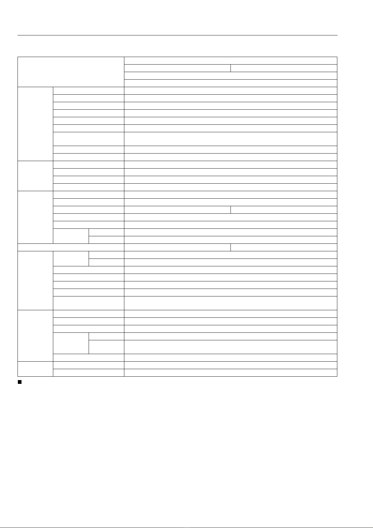
3. SPECIFICATIONS
• *Manufacturer's estimate. The company reserves the right to change the specifications without notice.
9Y1210278INI0003US0
Model
L4100
Rear mount type ROPS Mid mount type ROPS
Manual Transmission
4WD
Engine
Model V2203-M-E2A
Type Indirect injection, Vertical, Water-Cooled 4 cylinder diesel
Number of cylinder 4
Total displacement 2.197 L (1.341 cu.in.)
Bore and stroke 87 x 92.4 mm (3.4 x 3.64 in.)
Net power* 29.3 kW (39.8 PS) / 2300 min-1 (rpm)
PTO power*
(factory observed) 25.7 kW (34.9 PS) / 2300 min-1 (rpm)
Maximum torque 141.5 N·m (14.43 kgf·m, 104.4 lbf·ft)
Battery capacity 12V, RC: 133 min, CCA: 582 A
Capacities
Fuel tank 42 L (11 U.S.gals, 9.2 Imp.gals)
Engine crankcase (with filter) 7.6 L (8.0 U.S.qts, 6.7 Imp.qts)
Engine coolant 6.5 L (6.9 U.S.qts, 5.7 Imp.qts)
Transmission case 40 L (11 U.S.gals, 8.8 Imp.gals)
Dimensions
Overall length (without 3P) 3005 mm (118.3 in.)
Overall width (min. tread) 1490 mm (58.86 in.)
Overall height (with ROPS) 2525 mm (99.41 in.) 2378 mm (93.62 in.)
Wheel base 1845 mm (72.64 in.)
Min. ground clearance 377 mm (14.8 in.)
Tread Front 1145 mm (45.08 in.)
Rear 1145, 1235, 1335, 1340 mm (45.08, 48.62, 52.56, 52.76 in.)
Weight (with ROPS) 1464 kg (3228 lbs) 1494 kg (3294 lbs)
Travelling
system
Standard tire
size
Front 8 - 16
Rear 13.6 - 26
Clutch Dry type single stage
Steering Hydrostatic power steering
Transmission Gear shift, 8 forward and 4 reverse
Braking system Mechanical, Wet disk type
Min. turning radius
(with brake) 2.6 m (8.5 ft)
Hydraulic unit
Hydraulic control system Position control
Pump capacity 30.5 L/min (8.06 U.S.gals/min, 6.71 Imp gals/min)
Three point hitch Category 1
Max. lift force
At lift points 1300 kg (2866 lbs)
24 in. behind
lift points 1053 kg (2321 lbs)
System pressure 17.7 MPa (180 kgf/cm2, 2570 psi)
PTO Rear PTO SAE 1-3/8, 6-splines
PTO /Engine speed 540 / 2208 min-1 (rpm)