wsm M6040 Instruction manual

M6040,M7040
WORKSHOP MANUAL
TRACTOR
KiSC issued 07, 2012 A

TO THE READER
This Workshop Manual tells the servicing personnel about the mechanism, servicing and
maintenance of the M6040 and M7040. It contains 4 parts: "Information", "General", "Mechanism"
and "Servicing".
Information
This section primarily contains information below.
• Safety First
• Safety Decal
• Specification
• Traveling Speeds
• Dimension
General
This section primarily contains information below.
• Engine Identification
• Model Identification
• General Precautions
• Maintenance Check List
• Check and Maintenance
• Special Tools
Mechanism
This section contains information on the structure and the function of the unit. Before you continue
with the subsequent sections, make sure that you read this section.
Refer to the latest version of Workshop Manual (Code No. 9Y021-01870 / 9Y021-18200) for the
diesel engine / tractor mechanism that this workshop manual does not include.
Servicing
This section primarily contains information below.
• Troubleshooting
• Servicing Specifications
• Tightening Torques
• Checking, Disassembling and Servicing
All illustrations, photographs and specifications contained in this manual are of the newest
information available at the time of publication.
KUBOTA reserves the right to change all information at any time without notice.
Since this manual includes many models, information or illustrations and photographs can show
more than one model.
September, 2008
© KUBOTA Corporation 2008
KiSC issued 07, 2012 A

I INFORMATION
KiSC issued 07, 2012 A

CONTENTS
1. SAFETY FIRST .............................................................................................................................. I-1
2. SAFETY DECALS .......................................................................................................................... I-4
3. SPECIFICATIONS........................................................................................................................ I-10
4. TRAVELING SPEEDS.................................................................................................................. I-12
5. DIMENSIONS ............................................................................................................................... I-13
INFORMATION
KiSC issued 07, 2012 A

INFORMATION
M6040, M7040, WSM
I-1
1. SAFETY FIRST
WSM000001INI0001US1
BEFORE YOU START SERVICE
• Read all instructions and safety instructions in this
manual and on your engine safety decals.
• Clean the work area and engine.
• Park the machine on a stable and level ground.
• Let the temperature of the engine decrease before
you start a job.
• Stop the engine, then remove the key.
• Disconnect the battery negative cable.
• Hang a "DO NOT OPERATE" tag in the operator
station.
WSM000001INI0002US0
START SAFELY
• Do not do the procedures below when you start the
engine.
– short across starter terminals
– bypass the safety start switch
• Do not make unauthorized modifications to the
engine. This can cause damage and decrease the
engine life.
WSM000001INI0003US0
SAFETY FIRST
• This symbol, the industry's "Safety Alert Symbol", is used throughout this manual and on labels on the
machine itself to warn of the possibility of personal injury. Read these instructions carefully.
• It is essential that you read the instructions and safety regulations before you attempt to repair or use
this unit.
DANGER
• Indicates an imminently hazardous situation which, if not avoided, will result in death or serious injury.
WARNING
• Indicates a potentially hazardous situation which, if not avoided, could result in death or serious injury.
CAUTION
• Indicates a potentially hazardous situation which, if not avoided, may result in minor or moderate
injury.
IMPORTANT
• Indicates that equipment or property damage could result if instructions are not followed.
NOTE
• Gives helpful information.
KiSC issued 07, 2012 A

INFORMATION
M6040, M7040, WSM
I-2
OPERATE SAFELY
• Do not use the machine after you consume alcohol
or medication or when you are tired.
• Put on applicable clothing and safety equipment.
• Use applicable tools only. Do not use alternative
tools or parts.
• When 2 or more persons do servicing, make sure
that you do it safely.
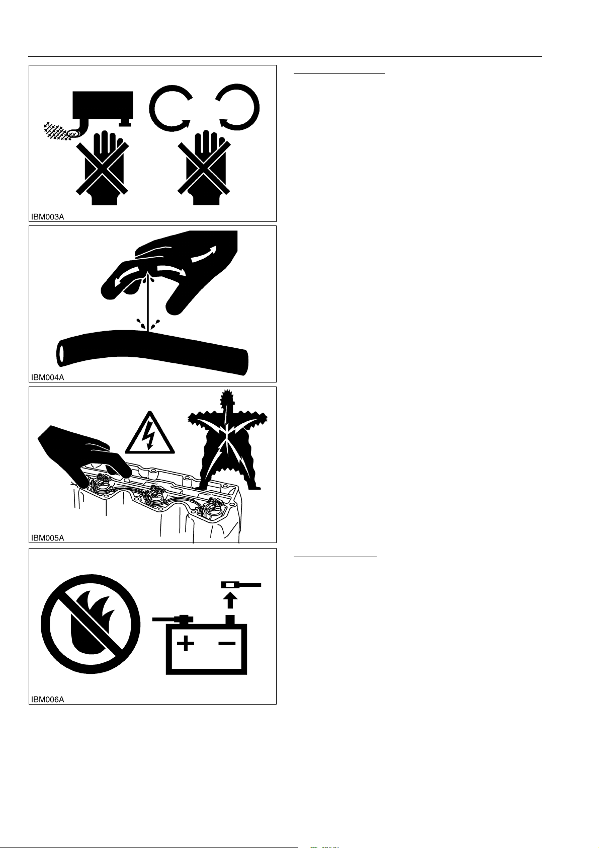
• Do not touch the hot parts or parts that turn when the
engine operates.
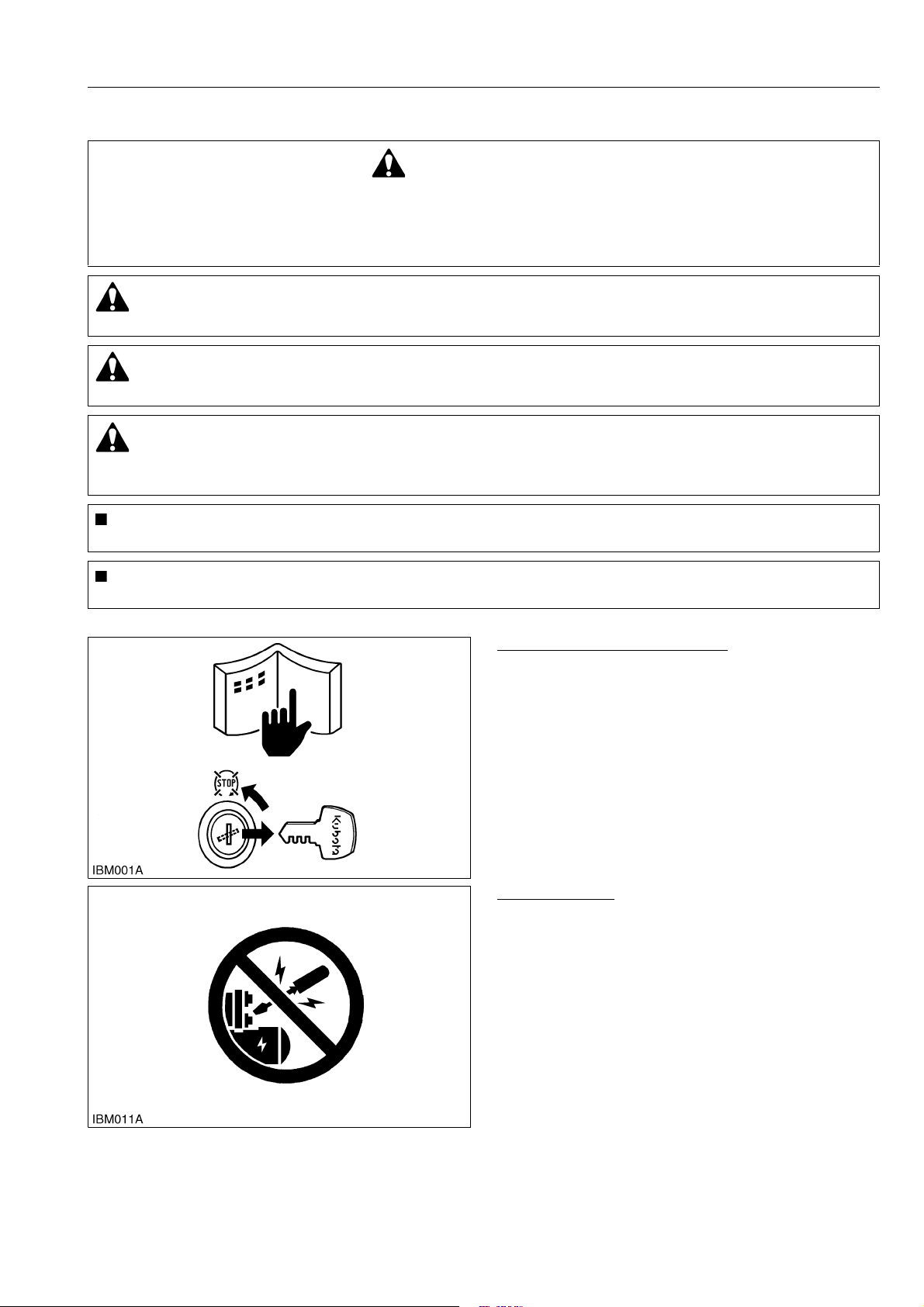
• Do not remove the radiator cap when the engine
operates, or immediately after it stops. If not, hot
water can spout out from the radiator. Only remove
the radiator cap when it is at a sufficiently low
temperature to touch with bare hands. Slowly loosen
the cap to release the pressure before you remove it
fully.
• Released fluid (fuel or hydraulic oil) under pressure
can cause damage to the skin and cause serious
injury. Release the pressure before you disconnect
hydraulic or fuel lines. Tighten all connections before
you apply the pressure.
• Do not open a fuel system under high pressure.
The fluid under high pressure that stays in fuel lines
can cause serious injury. Do not disconnect or repair
the fuel lines, sensors, or any other components
between the fuel pump and injectors on engines with
a common rail fuel system under high pressure.
• Put on an applicable ear protective device (earmuffs
or earplugs) to prevent injury against loud noises.
• Be careful about electric shock. The engine
generates a high voltage of more than DC100 V in
the ECU and is applied to the injector.
WSM000001INI0004US0
PREVENT A FIRE
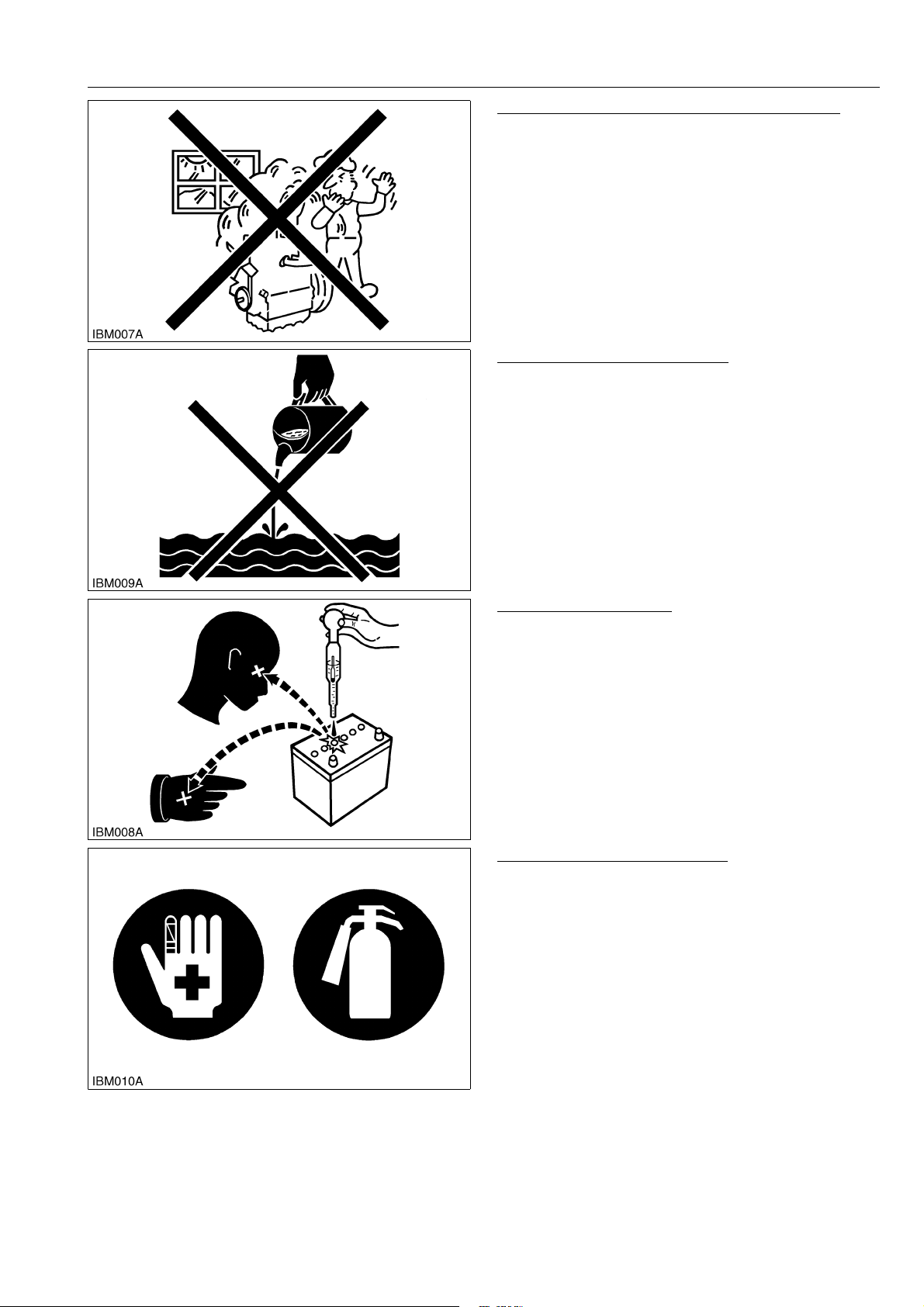
• Fuel is very flammable and explosive under some
conditions. Do not smoke or let flames or sparks in
your work area.
• To prevent sparks from an accidental short circuit,
always disconnect the battery negative cable first
and connect it last.
• The battery gas can cause an explosion. Keep the
sparks and open flame away from the top of battery,
especially when you charge the battery.
• Make sure that you do not spill fuel on the engine.
WSM000001INI0005US1
KiSC issued 07, 2012 A

INFORMATION
M6040, M7040, WSM
I-3
KEEP A GOOD AIRFLOW IN THE WORK AREA
• If the engine is in operation, make sure that the area
has good airflow. Do not operate the engine in a
closed area. The exhaust gas contains poisonous
carbon monoxide.
WSM000001INI0006US1
DISCARD FLUIDS CORRECTLY
• Do not discard fluids on the ground, down the drain,
into a stream, pond, or lake. Obey related
environmental protection regulations when you
discard oil, fuel, coolant, electrolyte and other
dangerous waste.
WSM000001INI0007US1
PREVENT ACID BURNS
• Keep electrolyte away from your eyes, hands and
clothing. Sulfuric acid in battery electrolyte is
poisonous and it can burn your skin and clothing and
cause blindness. If you spill electrolyte on yourself,
clean yourself with water, and get medical aid
immediately.
WSM000001INI0008US1
PREPARE FOR EMERGENCIES
• Keep a first aid kit and fire extinguisher ready at all
times.
• Keep the emergency contact telephone numbers
near your telephone at all times.
WSM000001INI0009US1
KiSC issued 07, 2012 A

INFORMATION
M6040, M7040, WSM
I-4
2. SAFETY DECALS
The following safety decals (pictorial safety labels) are installed on the machine. If a decal becomes
damaged, illegible or is not on the machine, replace it. The decal part number is listed in the parts list.
WSM000001INI0014US0
ROPS Model
9Y1210143INI0001US0
KiSC issued 07, 2012 A

INFORMATION
M6040, M7040, WSM
I-5
9Y1210143INI0002US0
KiSC issued 07, 2012 A

INFORMATION
M6040, M7040, WSM
I-6
9Y1210143INI0003US0
KiSC issued 07, 2012 A

INFORMATION
M6040, M7040, WSM
I-7
CABIN Model
9Y1210143INI0004US0
KiSC issued 07, 2012 A

INFORMATION
M6040, M7040, WSM
I-8
9Y1210143INI0005US0
KiSC issued 07, 2012 A

INFORMATION
M6040, M7040, WSM
I-9
9Y1210143INI0006US0
KiSC issued 07, 2012 A

INFORMATION
M6040, M7040, WSM
I-10
3. SPECIFICATIONS
NOTE
• *1: Manufacture's estimate
*2: At lower link end with links horizontal.
The company reserves the right to change the specifications without notice.
Model M6040 M7040 M7040DTH-SPA
4WD
Engine
Model V3307-DI-TE3
Type Vertical, water-cooled, 4-cycle direct injection diesel engine
Number of cylinders 4
Total displacement 3331 cm3(203 cu.in.)
Bore and stroke 94 × 120 mm (3.7 × 4.7 in.)
Rated speed 2600 min-1 (rpm)
Net power*147.3 kW (63.5 HP) 52.9 kW (71.0 HP)
Gross power*149.2 kW (66 HP) 54.9 kW (73.6 HP)
Maximum torque
220 N·m (22.4 kgf·m,
162 lbf·ft) /
1500 to 1700 min-1 (rpm)
252 N·m (25.7 kgf·m, 186 lbf·ft) /
1500 to 1700 min-1 (rpm)
Battery capacity 12 V, RC: 160 min, CCA: 900 A
Fuel tank
capacity
ROPS Model 70 L (18.5 U.S.gals, 15.4 Imp.gals)
CABIN Model 90 L (23.8 U.S.gals, 19.8 Imp.gals)
Engine oil capacity 11 L (11.6 U.S.qts, 9.7 Imp.qts)
Coolant capacity 8 L (8.5 U.S.qts, 7.0 Imp.qts)
Dimensions
Overall length ROPS Model 3615 mm (142.3 in.) 2435 mm (95.87 in.)
CABIN Model 3675 mm (144.7 in.) –
Overall width (min. tread) 1855 mm (73.03 in.)
Overall height ROPS Model 2495 mm (98.23 in.)
CABIN Model 2545 mm (100.2 in.) –
Wheel base ROPS Model 2050 mm (81 in.)
CABIN Model 2110 mm (83.1 in.) –
Tread
Front 1420, 1537 mm (55.9, 60.51 in.) 1365, 1385, 1415 mm
(53.74, 54.53, 55.71 in.)
Rear 1416 to 1733 mm (55.75 to 68.22 in.) 1545 to 1737 mm
(60.83 to 68.38 in.)
Minimum
ground
clearance
ROPS Model 420 mm (16.5 in.) (Fuel tank stay) 360 mm (14.2 in.)
(Fuel tank stay)
CABIN Model 430 mm (16.9 in.)
(Fuel tank stay)
415 mm (16.3 in.)
(Fuel tank stay) –
Weight ROPS Model 2450 kg (5401 lbs) 2245 kg (5390 lbs)
CABIN Model 2730 kg (6019 lbs) –
Traveling
system
Standard tire
size
Front 320/85R24 (12.4R20) 320/70R20
Rear 420/85R30 (16.9R30) 420/70R28
Clutch Multiple wet discs
Steering Hydraulic power steering
Braking system Hydraulic wet discs
Differential Bevel gears with differential lock (rear)
Hydraulic
system
Hydraulic control system Position, draft (top link sensing) and mix control
Pump capacity 61 L (16 U.S.gals, 13 Imp.gals) /min
3-point hitch SAE Category 1 and 2
Max. lifting
force
At lift points*22300 kg (5071 lbs)
24 in. behind
lift points*21800 kg (3968 lbs)
Remote hydraulic control Two remote valves (3rd valve option) Max. Three
System pressure 19.1 MPa (195 kgf/cm2, 2270.3 psi)
Traction system Drawbar with clevis
KiSC issued 07, 2012 A

INFORMATION
M6040, M7040, WSM
I-11
NOTE
• *1: Manufacture's estimate
*2: At lower link end with links horizontal.
The company reserves the right to change the specifications without notice.
9Y1210143INI0007US0
Model M6040 M7040 M7040DTH-SPA
4WD
PTO
Live PTO
(Independent)
Direction of
turning Clockwise, viewed from tractor rear
PTO speed 6 spline: 540 min-1 (rpm) / 2160 min-1 (rpm) engine speed
6 spline: 540E min-1 (rpm) / 1825 min-1 (rpm) engine speed
Ground PTO
(For
M7040-ITA
Model)
PTO speed
Shift type ground-live PTO
540 min-1 (rpm): 8.94 min-1 (rpm) / one rotate of rear tire
540E min-1 (rpm): 10.56 min-1 (rpm) / one rotate of rear tire
1000 min-1 (rpm): 14.47 min-1 (rpm) / one rotate of rear tire
–
KiSC issued 07, 2012 A

INFORMATION
M6040, M7040, WSM
I-12
4. TRAVELING SPEEDS
(At rated engine rpm)
The company reserves the right to change the specifications without notice.
9Y1210143INI0008US0
Model M6040 / M7040 M7040DTH-SPA
Tire size (Rear) 420/85R30 (16.9R30) 420/70R28
Shuttle shift
lever
Range gear
shift lever
Main gear shift
lever km/h (mph) km/h (mph)
Forward
CREEP
1 0.43 (0.27) 0.40 (0.25)
2 0.61 (0.38) 0.56 (0.35)
3 0.79 (0.49) 0.73 (0.45)
4 1.0 (0.62) 0.9 (0.6)
5 1.3 (0.81) 1.2 (0.75)
L
1 3.0 (1.9) 2.8 (1.7)
2 4.3 (2.7) 4.0 (2.5)
3 5.6 (3.5) 5.2 (3.2)
4 7.1 (4.4) 6.5 (4.0)
5 9.4 (5.8) 8.7 (5.4)
H
1 12.1 (7.52) 11.2 (6.96)
2 17.2 (10.7) 15.9 (9.88)
3 22.2 (13.8) 20.5 (12.7)
4 28.5 (17.7) 26.3 (16.3)
5 37.5 (23.3) 34.6 (21.5)
Reverse
CREEP
1 0.44 (0.27) 0.41 (0.35)
2 0.62 (0.39) 0.57 (0.39)
3 0.80 (0.50) 0.74 (0.46)
4 1.03 (0.640) 0.95 (0.59)
5 1.35 (0.839) 1.25 (0.777)
L
1 3.1 (1.9) 2.9 (1.8)
2 4.4 (2.7) 4.1 (2.5)
3 5.6 (3.5) 5.2 (3.2)
4 7.2 (4.5) 6.6 (4.1)
5 9.5 (5.9) 8.8 (5.5)
H
1 12.3 (7.64) 11.3 (7.02)
2 17.4 (10.8) 16.1 (10.0)
3 22.5 (14.0) 20.8 (12.9)
4 28.9 (18.0) 26.7 (16.6)
5 38.0 (24) 35.1 (21.8)
KiSC issued 07, 2012 A

INFORMATION
M6040, M7040, WSM
I-13
5. DIMENSIONS
ROPS Model
9Y1210143INI0009US0
KiSC issued 07, 2012 A

INFORMATION
M6040, M7040, WSM
I-14
CABIN Model
9Y1210143INI0010US0
KiSC issued 07, 2012 A

G GENERAL
KiSC issued 07, 2012 A

CONTENTS
1. TRACTOR IDENTIFICATION....................................................................................................... G-1
[1] MODEL NAME AND SERIAL NUMBERS .............................................................................. G-1
[2] ENGINE NUMBER ................................................................................................................. G-2
[3] E3B ENGINE .......................................................................................................................... G-3
[4] CYLINDER NUMBER............................................................................................................. G-3
2. GENERAL PRECAUTIONS.......................................................................................................... G-4
3. HANDLING PRECAUTIONS FOR ELECTRICAL PARTS AND WIRING .................................... G-5
[1] WIRING .................................................................................................................................. G-5
[2] BATTERY ............................................................................................................................... G-7
[3] FUSE ...................................................................................................................................... G-7
[4] CONNECTOR ........................................................................................................................ G-7
[5] HANDLING OF CIRCUIT TESTER ........................................................................................ G-8
[6] COLOR OF WIRING ..............................................................................................................G-9
4. LUBRICANTS, FUEL AND COOLANT....................................................................................... G-10
5. TIGHTENING TORQUES........................................................................................................... G-13
[1] GENERAL USE SCREWS, BOLTS AND NUTS .................................................................. G-13
[2] STUD BOLTS ....................................................................................................................... G-13
[3] HYDRAULIC FITTINGS ....................................................................................................... G-14
(1) Hydraulic Hose Fittings................................................................................................... G-14
(2) Hydraulic Pipe Cap Nuts ................................................................................................ G-14
(3) Adaptors, Elbows and Others......................................................................................... G-14
[4] METRIC SCREWS, BOLTS AND NUTS .............................................................................. G-15
[5] AMERICAN STANDARD SCREWS, BOLTS AND NUTS WITH UNC OR UNF
THREADS ............................................................................................................................ G-15
[6] PLUGS ................................................................................................................................. G-15
6. MAINTENANCE CHECK LIST ................................................................................................... G-16
7. CHECK AND MAINTENANCE ................................................................................................... G-18
[1] DAILY CHECK...................................................................................................................... G-18
[2] CHECK POINTS OF INITIAL 50 HOURS ............................................................................ G-19
[3] CHECK POINTS OF EVERY 50 HOURS ............................................................................ G-22
[4] CHECK POINTS OF EVERY 100 HOURS .......................................................................... G-23
[5] CHECK POINTS OF EVERY 200 HOURS .......................................................................... G-28
[6] CHECK POINTS OF EVERY 300 HOURS .......................................................................... G-31
[7] CHECK POINTS OF EVERY 400 HOURS .......................................................................... G-32
[8] CHECK POINTS OF EVERY 600 HOURS .......................................................................... G-33
[9] CHECK POINT OF EVERY 800 HOURS ............................................................................. G-33
[10]CHECK POINT OF EVERY 1500 HOURS ........................................................................... G-33
[11]CHECK POINTS OF EVERY 3000 HOURS ........................................................................ G-33
[12]CHECK POINT OF EVERY 1 YEAR .................................................................................... G-34
[13]CHECK POINTS OF EVERY 2 YEARS ............................................................................... G-35
[14]OTHERS............................................................................................................................... G-39
8. SPECIAL TOOLS ....................................................................................................................... G-42
[1] SPECIAL TOOLS FOR ENGINE.......................................................................................... G-42
[2] SPECIAL TOOLS FOR TRACTOR ...................................................................................... G-62
[3] SPECIAL TOOLS FOR AIR CONDITIONER UNIT .............................................................. G-76
9. TIRES ......................................................................................................................................... G-79
[1] TIRE SIZE AND INFLATION PRESSURE ........................................................................... G-79
[2] TREAD ADJUSTMENT ........................................................................................................ G-80
(1) Front Wheels .................................................................................................................. G-80
GENERAL
KiSC issued 07, 2012 A
This manual suits for next models
1
Table of contents
Other wsm Tractor manuals

wsm
wsm ME8200 Instruction manual

wsm
wsm L2800 Instruction manual

wsm
wsm M8540NARROW Instruction manual

wsm
wsm M108S Instruction manual

wsm
wsm L3901 Instruction manual

wsm
wsm M7060 Instruction manual

wsm
wsm L3301 Instruction manual

wsm
wsm BX1800 Instruction manual

wsm
wsm Kubota L4100 Instruction manual

wsm
wsm L503 Instruction manual