Copyright © 2018 WyreStorm Technologies | wyrestorm.com
EX-100-4K-PRO Quickstart Guide | 190212
UK: +44 (0) 1793 230 343 | ROW: 844.280.WYRE (9973)
3 of 4
Installation and Conguration
Pre Wire
Run a Cat5e/6/6a cable from the transmitter location to the receiver location following the guidelines in the Wiring and Connections section.
1. (Optional) If using IR emitters or 3rd party connecting blocks at either the transmitter or receiver, run the wire and terminate per the IR TX Port Pinout
section.
2. (Optional) If using IR receivers or an IR control system at either the transmitter or receiver, run the wire and terminate per the IR RX Port Pinout section.
3. (Optional) If using RS-232 pass-through, run the wire and terminate per the RS-232 Connections section.
Transmitter Installation
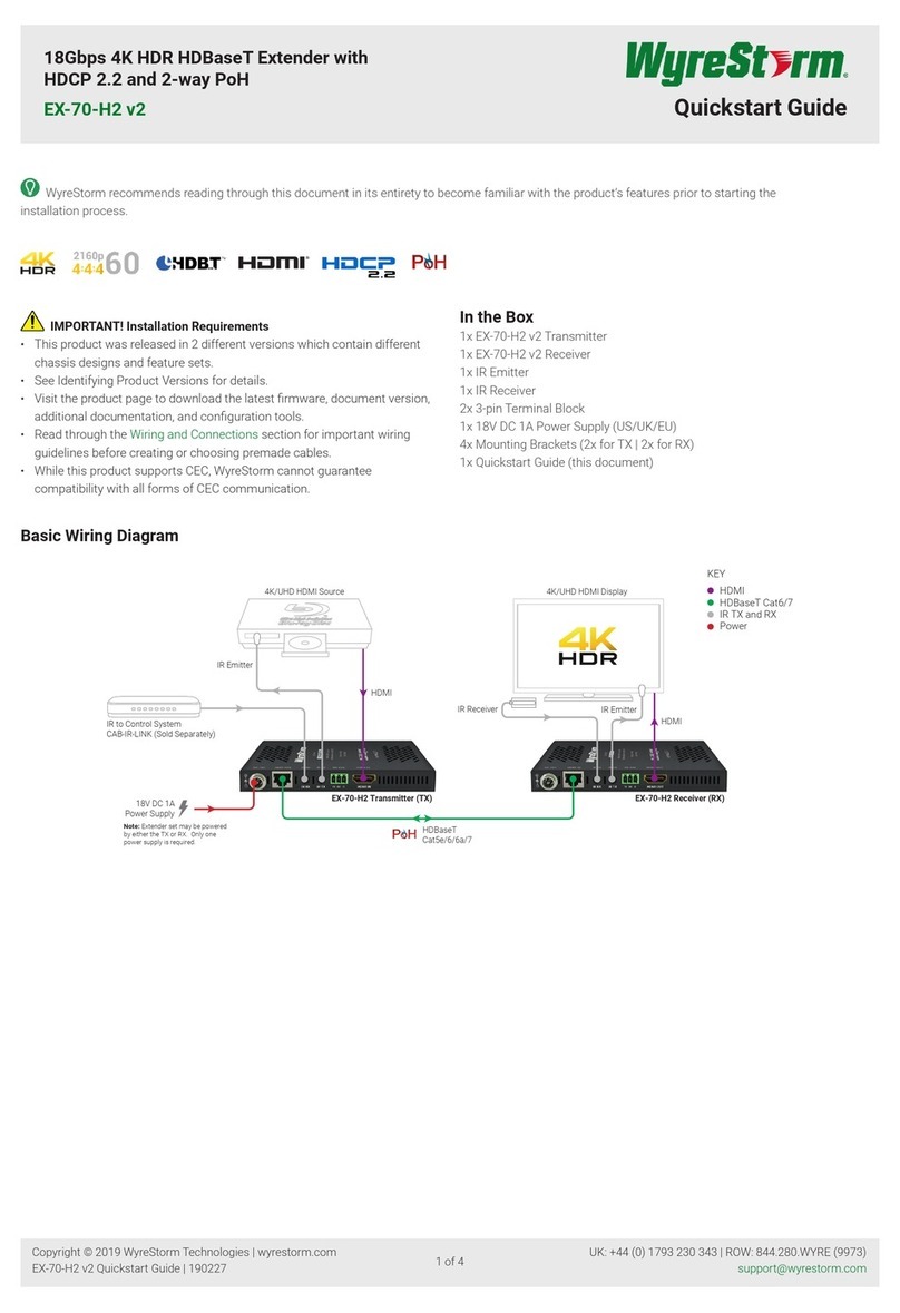
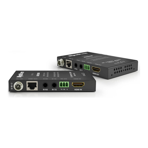
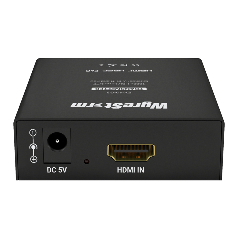
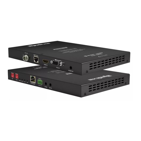
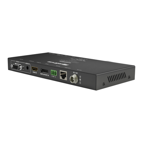
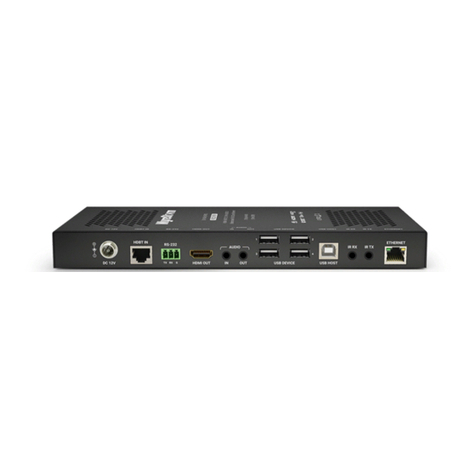
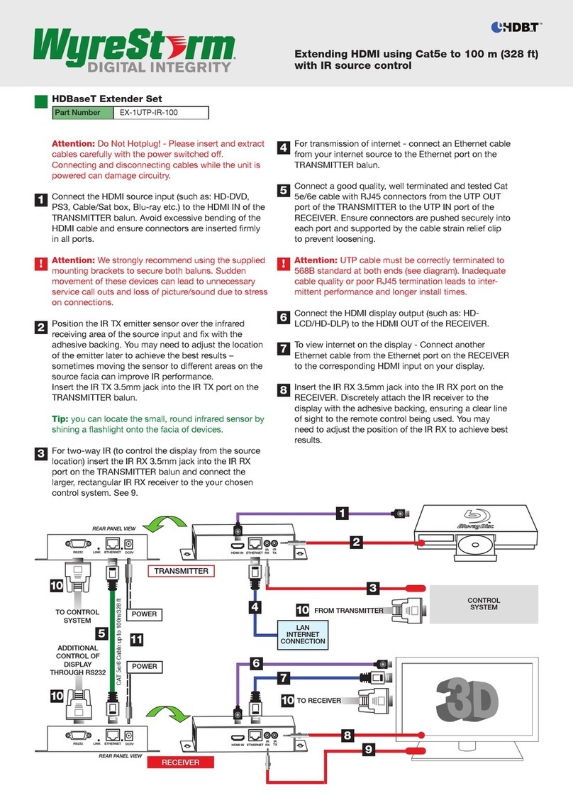
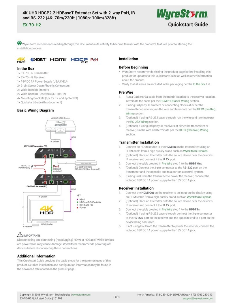
1. Connect an HDMI source to the HDMI In on the transmitter using an HDMI cable from a high quality brand such as WyreStorm Express.
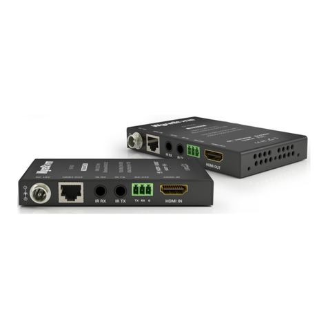
2. Using the cable created in Pre Wire step 1, connect the 8-pin RJ-45 female plug to the HDBT Out jack on the transmitter.
3. (Optional) Place an IR emitter onto the source device near the device’s IR sensor and connect the opposite end to an IR TX port.
4. (Optional) Connect an IR Receiver to the transmitters IR RX port. If using a control system, connect it to an IR RX port on the transmitter using the CAB-IR-
LINK or the cable created in Pre Wire step 3.
5. (Optional) Using the cable created in Pre Wire step 4, connect the 3-pin connector to the RS-232 port on the transmitter and the opposite end to a port on a
control system.
6. (Optional) If using audio sent from the remote display via HDBaseT, connect the S/PDIF Out to a TOSLInk digital input on an AV Receiver or amplier.
7. If using PoH from the transmitter to power the receiver, connect the included 12V DC 2A power supply to the DC 12V jack.
Receiver Installation
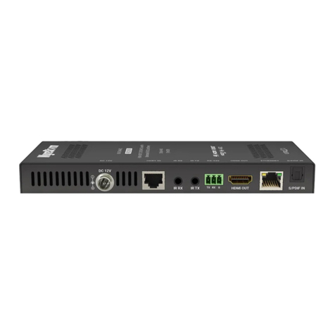
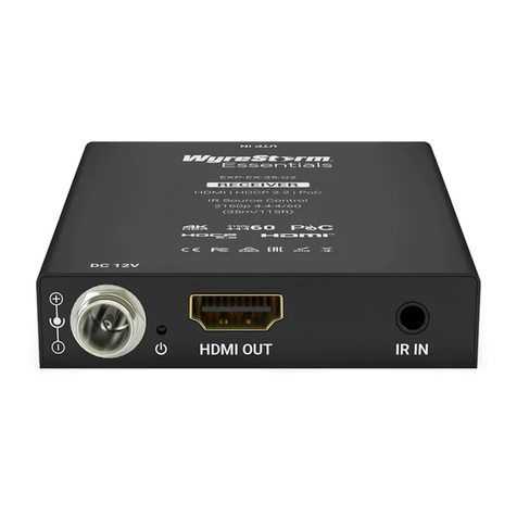
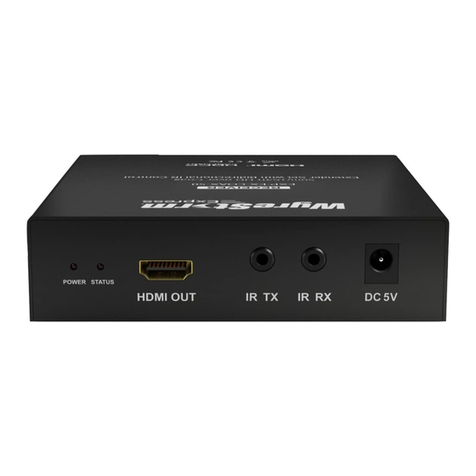
1. Connect the HDMI Out on the receiver to an input on the display using an HDMI cable from a high quality brand such as WyreStorm Express.
2. Using the cable created in Pre Wire step 1, connect the 8-pin RJ-45 female plug to the HDBT In jack on the receiver.
3. (Optional) Place an IR emitter onto the display device near the device’s IR sensor and connect the opposite end to an IR TX port.
4. (Optional) Connect an IR Receiver to the receivers IR RX port. If using a control system, connect it to an IR RX port on the receiver using the CAB-IR-LINK or
the cable created in Pre Wire step 3.
5. (Optional) Using the cable created in Pre Wire step 4, connect the 3-pin connector to the RS-232 port on the receiver and the opposite end to the port on
the display device.
6. If using PoH from the receiver to power the transmitter, connect the included 12V DC 2A power supply to the DC 12V jack.
Dipswitch Settings
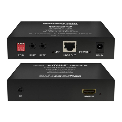
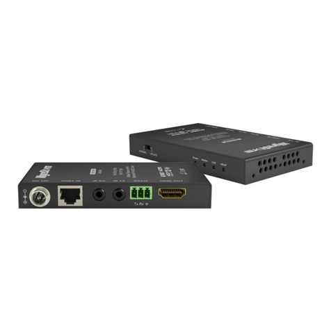
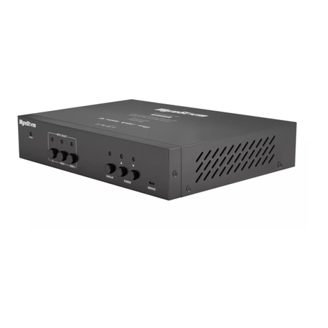
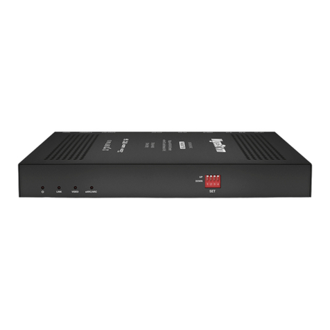
The Set dipswitches on the front panel of both the transmitter and receiver congure various functions within the EX-100-4K-PRO.
• Long Cable mode change must be made on both the TX and RX.
• USB settings for Host and Device are reversed on the TX and RX. See table below.
• Switches that are grayed out in the images can be in any position for the desired function.
Long Cable Mode Disabled 123
ON
Enabled 123
ON
USB
Host (TX) 123
ON
Host (RX) 123
ON
Device (TX) 123
ON
Device (RX) 123
ON
RS-232 Passthrough 123
ON
Firmware Update 123
ON
Troubleshooting
No or Poor Quality Picture (snow or noisy image)
• Verify that power is being supplied to the transmitter and receiving device.
Note: When using PoH, to power the transmitter, verify that the HDBaseT cable
is properly terminated per the guidelines in the Wiring and Connections section.
• Verify that the matrix, receiver, and display support the output resolution of
the source. Refer to Video Resolutions in the Specications table.Verify that
the HDBaseT cable is properly terminated following EIA568B standard.
• If transmitting 3D or 4K, verify that the HDMI cables used are 3D or 4K rated.
• Verify that the HDBaseT cable is properly terminated per the guidelines in
the Wiring and Connections section.
• Verify that all source and HDBaseT connections are not loose and are
functioning properly.
No or Intermittent 3rd party Device Control
• Verify that the IR cable(s) is properly terminated.
See IR TX/RX Guidelines.
• Verify that the IR emitter is located near the IR receiver on the device.
Troubleshooting Tips:
• WyreStorm recommends using a cable tester or connecting the cable to
other devices to verify functionality.
• Use a ashlight to locate the IR receiver behind any tinted panels on the
device being control.
