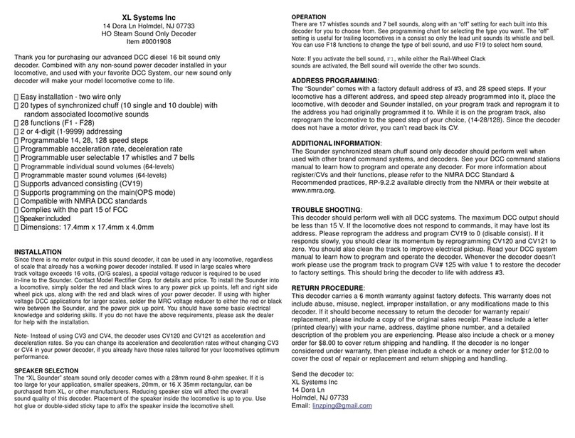
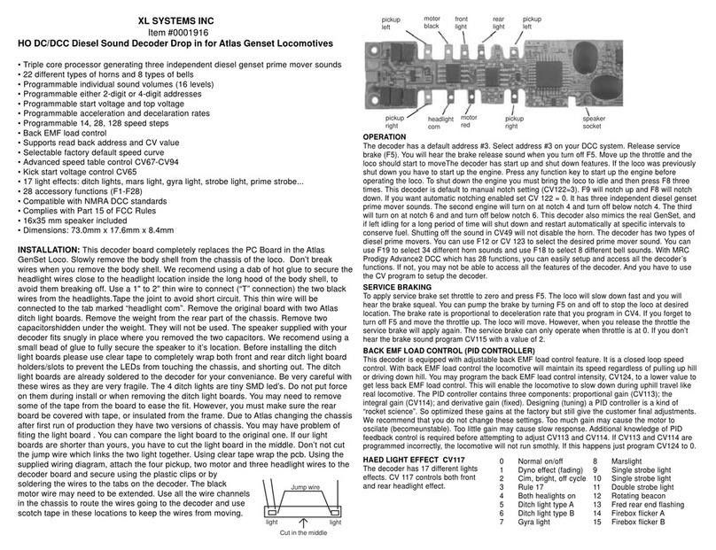
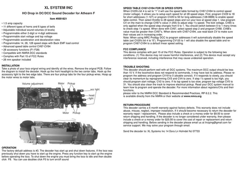
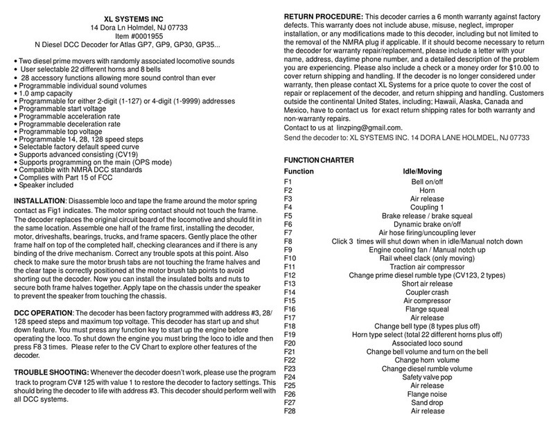
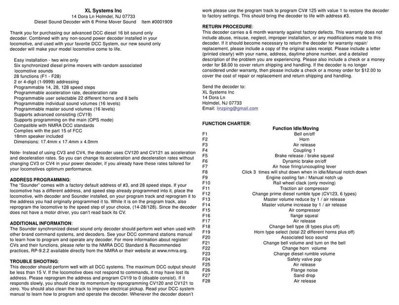
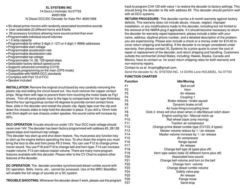
XL Systems 0001808 User manual

XL SYSTEMS INC
14 Dora Ln Holmdel, NJ 07733
Item #0001808
N Diesel DCC/DC Decoder for Kato SD80 and other
• Six diesel prime movers with randomly associated locomotive sounds
•User selectable 22 different horns and 8 bells
•28 accessory functions allowing more sound control than ever
• Programmable individual sound volumes
• 1.0 amp capacity
• Programmable for either 2-digit (1-127) or 4-digit (1-9999) addresses
• Programmable start voltage
• Programmable acceleration rate
• Programmable deceleration rate
• Programmable top voltage
• Programmable 14, 28, 128 speed steps
• Selectable factory default speed curve
• Supports advanced consisting (CV19)
• Supports programming on the main (OPS mode)
• Compatible with NMRADCC standards
• Complies with Part 15 of FCC
• Speaker included
INSTALLATION: The coder will virtually drop in to a Kato SD80 diesel loco. Remove
the loco body following Kato’s instructions. Remove the original circuit board by
sliding the circuit board slightly to the rear of the chassis and lift it out. The sound
decoder is installed in the same location. First, deburr the chassis any casting flash
that may cause a sharp edge under the location of the insulation tape. Then, using
electrical or equiv plastic tape, carefully tape the chassis in the areas as Fig1
indicated to isolate the decoder from the chassis. This must be done to prevent
damage to the decoder. Align the decoder and carefully insert it in the slots in the
chassis. Don’t bend the decoder too much. Gently press down on the rear of the
decoder while sliding it into position, being careful not to bend the vertical copper
motor contacts on the side of the chassis. Ensure the vertical copper contacts cover
the thin vertical motor contacts. The motor contact must not touch the loco chassis.
Remove the white protective film from the speaker and “stick” it in place as shown.
The decoder installation is complete. When replacing the body, ensure the copper
contacts on the trucks are under the horizontal chassis contacts.
DCC OPERATION: The decoder has been factory programmed with address #3.
F12 will change prime diesel rumble type (CV123, 6 types). Use F19 to select 22
different horns and use F18 to select 8 bells. This decoder has start up and shut
down feature. You must press any function key to start up the engine before
operating the loco. To shut down the engine you must bring the loco to idle and
then press F8 3 times.
DC OPERATION: The decoder provides synchronized diesel rumble sound with
DC operation. Bells, horns, etc., cannot be accessed. Use of the MRC BlackBox
will enable the full range of sounds on a DC system.
SPEED TABLE CV67-CV94 FOR 28 SPEED STEPS
When CV29’s bit 4 is set to “1” it will use the speed table formed by CV67-CV94 to control
speed (motor voltage). It allows you to setup each speed for all 28 speed steps. First,
program CV29 to 18 for short addresses (1-127) or program CV29 to 50 for long
addresses (128-9999) to enable speed table control. Then select throttle to 28 speed steps
and run your loco at speed step 1. Use program
CV on the main to change CV67’s value (1-255) to adjust step 1’s speed. The kick voltage,
CV65 is only applied when the speed step changes from 0 to 1. You should switch
between 0 to 1 many times to check step 1’s speed. When done with CV67, select speed
step 2 and program CV68. CV68’s value must be greater then CV67’s. When done with
CV67-CV94, use read back CV to make sure their values are in increasing order. Note:
When using MRC Prodigy DCC to program addresses it will automatically disable the
speed table (set CV29’s bit 4 to “0”). Programming CV125 to 1 will also disable the speed
table and reprogram CV67-CV94 to a default linear speed setting.
TROUBLE SHOOTING: Whenever the decoder doesn’t work, please use the
program track to program CV# 125 with value 1 to restore the decoder to factory
settings. This should bring the decoder to life with address #3. This decoder should
perform well with all DCC systems. Read your DCC system manual to learn how to
program and operate the decoder. For more information about CVs and their
functions, please refer to the NMRA DCC Standard & Recommended Practices,
RP-9.2.2. This is available directly from the NMRAor their website at
www.nmra.org.
Fig 1 tape here chassis slot
chassis slot the tape must cover the top and two sides
Fig 2
vertical motor contact cover motor
contact and can’t touch chassis contact must set
on wheel pickup
About US
XL Systems Inc has designed and manufactured model rail road products for MRC for more than 20
years. All MRC DCC products are made by XL Systems Inc. All our DCC products are compatible
MRC DCC products. We will introduce more new products to meet customer’s beget. We also provide
installation and special programming and modification for customer. If you have special needs please

CV CHARTER
CV# Description Range defualt
CV1 Short address 1-127 3
CV2 Start voltage 0-63 10
CV3 Acceleration 0-63 0
CV4 Deceleration 0-63 0
CV5 Top voltage 0-63 63
CV29 Basic configuration 2
CV19 Advanced consist address 0-127 0
CV21 CV21=0, all accessory functions follow its own address. When CV21=1, all
functions will follow the consist address 0
CV49 Master volume control 16=max volume, 0=sound off 0-16 16
CV50 Horn type (22 types plus off, 22=off) 0-22 13
CV51 Horn volume 0-15 15
CV52 Bell type (8 types plus off, 8=off) 0-7 5
CV53 Bell volume 0-15 15
CV54 Bell ring rate 0-50 3
CV55 Diesel rumble volume 0-15 12
CV56 Brake squeal volume 0-15 12
CV57 Dynamic brake volume 0-15 12
CV58 Air release volume 0-15 12
CV59 Air pump volume 0-15 12
CV60 Safety pop valve volume 0-15 12
CV61 Engine cooling fan volume 0-15 12
CV62 Coupling volume 0-15 12
CV64 Rail wheel clack 0-15 12
CV65 Kick start voltage 0-63 63
CV67-9428 speed steps table while CV29.4=1 1-255
CV112 Back EMF start speed adjudstment 0-7 0
CV113 Back EMF load control proportional gain kp 0-31 20
CV114 Back EMF load control integral gain ki 0-31 10
CV115 Brake sound type: 2=breke sound off 0-2 0
CV117 Light brightness 0-15 0
CV120 Light brightness 0-255 255
CV121 Air compressor mode (1=change with engine rpm) 0-1 0
CV122 Diesel notch mode, 0=auto notch 3=manual notch 0-3 0
CV123 Diesel prime mover select 0-5 0
CV124 Back EMF load control intensity (0=off) 0-255 0
CV125 Program to “1” will restore some CV’s to factory settings …. 0
FUNCTION CHARTER
Function Idle/Moving
F1 Bell on/off
F2 Horn
F3 Air release
F4 Coupling 1
F5 Brake release / brake squeal
F6 Dynamic brake on/off
F7 Air hose firing/uncoupling lever
F8 Click 3 times will shut down when in idle/Manual notch down
F9 Engine cooling fan / Manual notch up
F10 Rail wheel clack (only moving)
F11 Traction air compressor
F12 Change prime diesel rumble type (CV123, 6 types)
F13 Master volume reduce by 1 / air release
F14 Master volume increase by 1 / air release
F15 Air compressor
F16 flange squeal
F17 Air release
F18 Change bell type (8 types plus off)
F19 Horn type select (total 22 different horns plus off)
F20 Associated loco sound
F21 Change bell volume (go up by 1 and back 0 when reach top)
F22 Change horn volume (go up by 1 and back 0 when reach top)
F23 Change diesel rumble volume(go up by 1 and back 0 when reach top)
F24 Safety valve pop
F25 Air release
F26 Flange noise
F27 Sand drop
F28 Air release
RETURN PROCEDURE
This decoder carries a 6 month warranty against factory defects. This warranty
does not include abuse, misuse, neglect, improper installation, or any modifications
made to this decoder, including but not limited to the removal of the NMRA plug if
applicable. If it should become necessary to return the decoder for warranty repair/
replacement, please include a letter with your name, address, daytime phone
number, and a detailed description of the problem you are experiencing. Please
also include a check or a money order for $9.00 to cover return shipping and
handling. If the decoder is no longer considered under warranty, then please contact
XL Systems for a price quote to cover the cost of repair or replacement of the
decoder, and return shipping and handling. Customers outside the continental
United States, including; Hawaii,Alaska, Canada and Mexico, have to contact us
for exact return shipping rates for both warranty and non-warranty repairs. Contact
Send the decoder to: XL SYSTEM INC. 14 DORA Lane HOLMDEL, NJ 07733
CV123 PRIME MOVER CHARTER
CV123 Prime mover Suitable for the locomotive
0 EMD645E SD39, SD40, SD40A, SD40-2, SD40T-2, SD45, SDP45, SD45X, SD45-2,
SD45T-2, F45, FP45, DDA40X, GP15T, GP39, GP39-2, GP40, GP40-2
1 EMD645 SW 1000, SW1001, SW1500, SW1500, SW1504, MP15DC, MP15AC,MP15T,
GP38, GP38-2, SD38, SD38-2, GP15AC, GP15-1
2 EMD710 SD70AC, SD70M-2
3 ALCO244 RS-3, PA1, PB1
4 ALCO539T S-2, S-4, RS-1, RSC-1, RSD-1, DL-105, DL-107, DL-108, DL-109, DL-110
5 EMD567 F2A/B, F3A/B, F7A/B, F9A/B, BL1, BL2, FP7, FL9, FT, GP7, GP9 ,GP,GP28
E6, E7, E8, E9, NW2, NW3, NW4, SW1, SW7, SW8, SW9, SW600, SW900
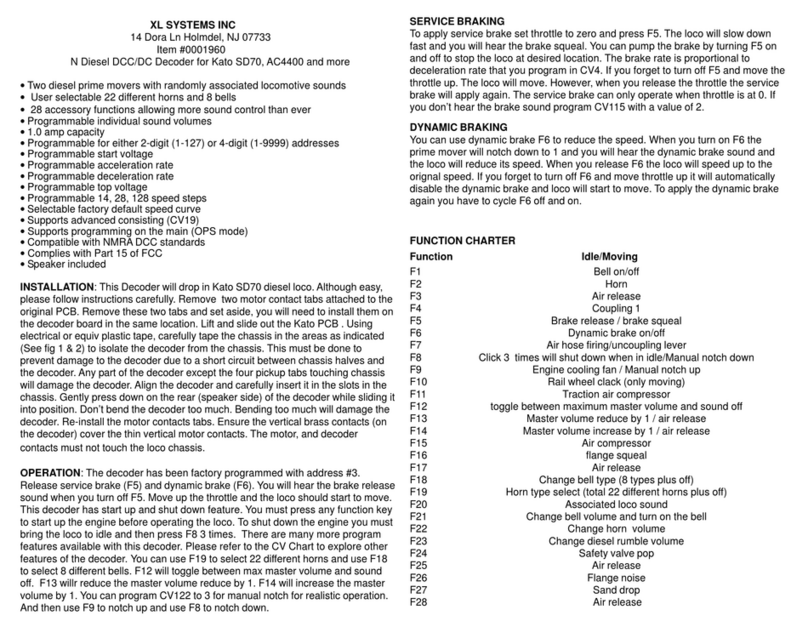
Other XL Systems Media Converter manuals

XL Systems
XL Systems 0001916 User manual

XL Systems
XL Systems 0001821 User manual

XL Systems
XL Systems 0001660 User manual

XL Systems
XL Systems 0001909 User manual

XL Systems
XL Systems 0001955 User manual

XL Systems
XL Systems 0001908 User manual

XL Systems
XL Systems 0001960 User manual

XL Systems
XL Systems 0001958 User manual