manuals.online logo
Brands
  1. Home
  2. •
  3. Brands
  4. •
  5. XL Systems
  6. •
  7. Media Converter
  8. •
  9. XL Systems 0001960 User manual

XL Systems 0001960 User manual

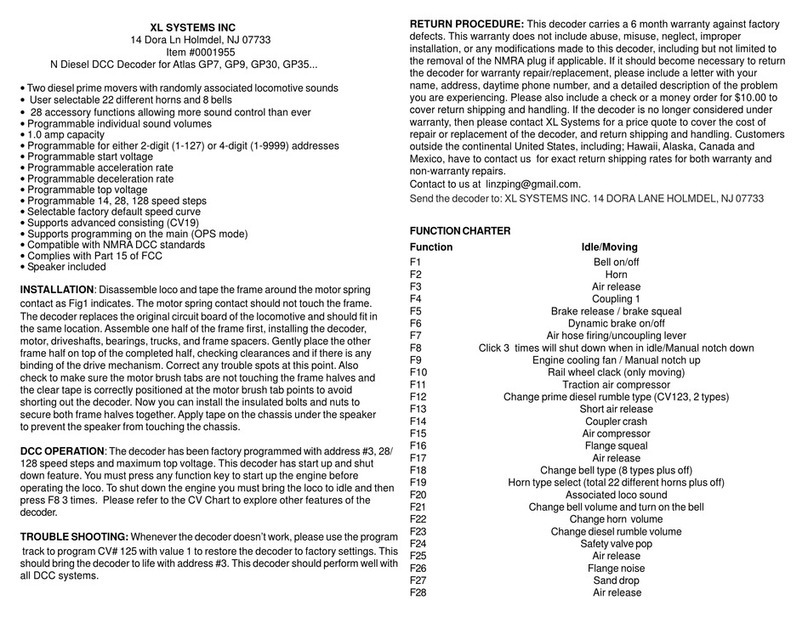
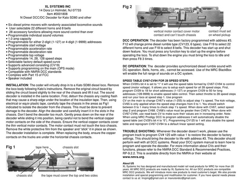
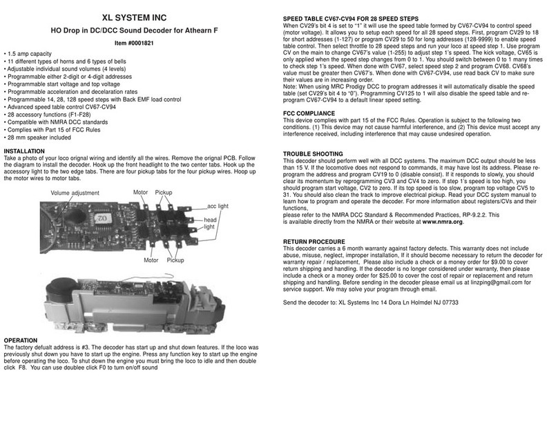
XL SYSTEMS INC
14 Dora Ln Holmdel, NJ 07733
Item #0001960
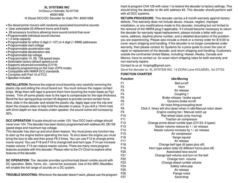
N Diesel DCC/DC Decoder for Kato SD70, AC4400 and more
• Two diesel prime movers with randomly associated locomotive sounds
•User selectable 22 different horns and 8 bells
•28 accessory functions allowing more sound control than ever
• Programmable individual sound volumes
• 1.0 amp capacity
• Programmable for either 2-digit (1-127) or 4-digit (1-9999) addresses
• Programmable start voltage
• Programmable acceleration rate
• Programmable deceleration rate
• Programmable top voltage
• Programmable 14, 28, 128 speed steps
• Selectable factory default speed curve
• Supports advanced consisting (CV19)
• Supports programming on the main (OPS mode)
• Compatible with NMRADCC standards
• Complies with Part 15 of FCC
• Speaker included
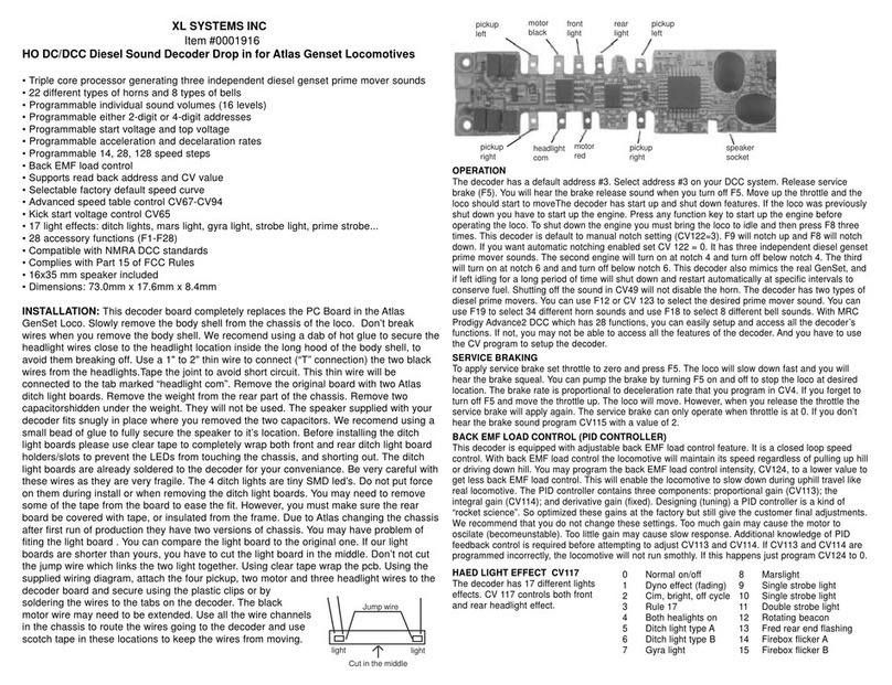
INSTALLATION: This Decoder will drop in Kato SD70 diesel loco.Although easy,
please follow instructions carefully. Remove two motor contact tabs attached to the
original PCB. Remove these two tabs and set aside, you will need to install them on
the decoder board in the same location. Lift and slide out the Kato PCB . Using
electrical or equiv plastic tape, carefully tape the chassis in the areas as indicated
(See fig 1 & 2) to isolate the decoder from the chassis. This must be done to
prevent damage to the decoder due to a short circuit between chassis halves and
the decoder. Any part of the decoder except the four pickup tabs touching chassis
will damage the decoder. Align the decoder and carefully insert it in the slots in the
chassis. Gently press down on the rear (speaker side) of the decoder while sliding it
into position. Don’t bend the decoder too much. Bending too much will damage the
decoder. Re-install the motor contacts tabs. Ensure the vertical brass contacts (on
the decoder) cover the thin vertical motor contacts.The motor, and decoder
contacts must not touch the loco chassis.
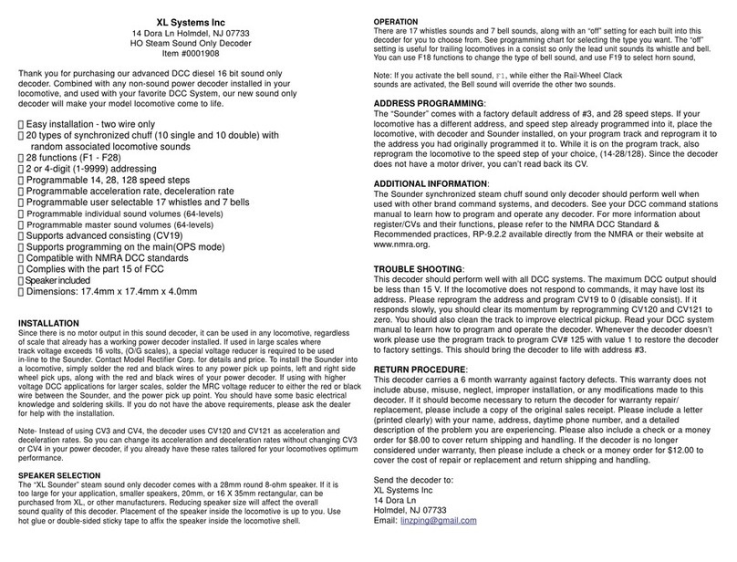
OPERATION: The decoder has been factory programmed with address #3.
Release service brake (F5) and dynamic brake (F6). You will hear the brake release
sound when you turn off F5. Move up the throttle and the loco should start to move.
This decoder has start up and shut down feature. You must press any function key
to start up the engine before operating the loco. To shut down the engine you must
bring the loco to idle and then press F8 3 times. There are many more program
features available with this decoder. Please refer to the CV Chart to explore other
features of the decoder. You can use F19 to select 22 different horns and use F18
to select 8 different bells. F12 will toggle between max master volume and sound
off. F13 willr reduce the master volume reduce by 1. F14 will increase the master
volume by 1. You can program CV122 to 3 for manual notch for realistic operation.
And then use F9 to notch up and use F8 to notch down.
FUNCTION CHARTER
Function Idle/Moving
F1 Bell on/off
F2 Horn
F3 Air release
F4 Coupling 1
F5 Brake release / brake squeal
F6 Dynamic brake on/off
F7 Air hose firing/uncoupling lever
F8 Click 3 times will shut down when in idle/Manual notch down
F9 Engine cooling fan / Manual notch up
F10 Rail wheel clack (only moving)
F11 Traction air compressor
F12 toggle between maximum master volume and sound off
F13 Master volume reduce by 1 / air release
F14 Master volume increase by 1 / air release
F15 Air compressor
F16 flange squeal
F17 Air release
F18 Change bell type (8 types plus off)
F19 Horn type select (total 22 different horns plus off)
F20 Associated loco sound
F21 Change bell volume and turn on the bell
F22 Change horn volume
F23 Change diesel rumble volume
F24 Safety valve pop
F25 Air release
F26 Flange noise
F27 Sand drop
F28 Air release
SERVICE BRAKING
To apply service brake set throttle to zero and press F5. The loco will slow down
fast and you will hear the brake squeal. You can pump the brake by turning F5 on
and off to stop the loco at desired location. The brake rate is proportional to
deceleration rate that you program in CV4. If you forget to turn off F5 and move the
throttle up. The loco will move. However, when you release the throttle the service
brake will apply again. The service brake can only operate when throttle is at 0. If
you don’t hear the brake sound program CV115 with a value of 2.
DYNAMIC BRAKING
You can use dynamic brake F6 to reduce the speed. When you turn on F6 the
prime mover will notch down to 1 and you will hear the dynamic brake sound and
the loco will reduce its speed. When you release F6 the loco will speed up to the
orignal speed. If you forget to turn off F6 and move throttle up it will automatically
disable the dynamic brake and loco will start to move. To apply the dynamic brake
again you have to cycle F6 off and on.
CV CHARTER
CV# Description Range Default
CV1 Short address 1-127 3
CV2 Start voltage 0-63 10
CV3 Acceleration 0-63 0
CV4 Deceleration 0-63 0
CV5 Top voltage 0-63 63
CV29 Basic configuration 2
CV19 Advanced consist address 0-127 0
CV21 CV21=0, all accessory functions follow its own address. When CV21=1, all
functions will follow the consist address 0
CV49 Master volume control 16=max volume, 0=sound off 0-16 16
CV50 Horn type (22 types plus off, 22=off) 0-22 13
CV51 Horn volume 0-15 15
CV52 Bell type (8 types plus off, 8=off) 0-7 5
CV53 Bell volume 0-15 15
CV54 Bell ring rate 0-50 3
CV55 Diesel rumble volume 0-15 12
CV56 Brake squeal volume 0-15 12
CV57 Dynamic brake volume 0-15 12
CV58 Air release volume 0-15 12
CV59 Air pump volume 0-15 12
CV60 Safety pop valve volume 0-15 12
CV61 Engine cooling fan volume 0-15 12
CV62 Coupling volume 0-15 12
CV64 Rail wheel clack 0-15 12
CV65 Kick start voltage 0-63 63
CV67-9428 speed steps table while CV29.4=1 1-255
CV112 Back EMF start speed adjudstment 0-7 0
CV113 Back EMF load control proportional gain kp 0-31 20
CV114 Back EMF load control integral gain ki 0-31 10
CV115 Brake sound type: 2=breke sound off 0-2 0
CV117 Light effect 0-15 0
CV118-119 Accessory light mode 0-16 0
CV120 Light brightness 0-255 255
CV121 Air compressor mode (1=change with engine rpm) 0-1 0
CV122 Diesel notch mode, 0=auto notch 3=manual notch 0-3 0
CV123 Diesel prime mover select 0-1 0
CV124 Back EMF load control intensity (0=off) 0-255 0
CV125 Program to “1” will restore some CV’s to factory settings …. 0
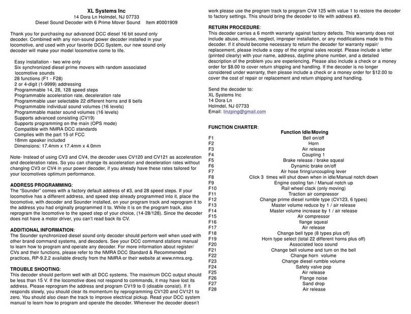
RETURN PROCEDURE: This decoder carries a 6 month warranty against factory
defects. This warranty does not include abuse, misuse, neglect, improper
installation, or any modifications made to this decoder. If it should become
necessary to return the decoder for warranty repair/replacement, please include a
letter with your name, address, daytime phone number, and a detailed description of
the problem you are experiencing. Please also include a check or a money order for
$10.00 to cover return shipping and handling. If the decoder is no longer considered
under warranty, then please contact XL Systems for a price quote to cover the cost
of repair or replacement of the decoder, and return shipping and handling.
Customers outside the continental United States, including; Hawaii,Alaska, Canada
and Mexico, have to contact us for exact return shipping rates for both warranty and
non-warrantyrepairs.
Contact to us at [email protected].
Send the decoder to: XL SYSTEM INC. 14 DORA Lane HOLMDEL, NJ 07733
LIGHT EFFECT PROGRAMMING CHART FOR CV#117
Program CV117 to choose 3 different modes of headlight effects (0=normal
directional, 1=off/dim/bright cycle, 2=rule 17).
TROUBLE SHOOTING: Whenever the decoder doesn’twork, please use the program
track to program CV# 125 with value 1 to restore the decoder to factory settings. This
shouldbring the decoder to lifewith address #3. This decoder shouldperform well with
all DCC systems.
About US
XL Systems Inc has designed and manufactured model rail road products for MRC for more than 20
years. All MRC DCC products are made by XL Systems Inc. All our DCC products are compatible
MRC DCC products. We will introduce more new products to meet customer’s beget. We also
provide installation and special programming and modification for customer. If you have special
needs please contact to us at: [email protected] or [email protected].
Fig 1 chassis slot
wrap tape to cover top and sides
decoder’s vertical contact
speaker
motor contact must touch
decoder’s vertical contact sprint contacts sitting on wheel pickup
Fig 2

Other XL Systems Media Converter manuals

XL Systems 0001916 User manual

XL Systems

XL Systems 0001916 User manual

XL Systems 0001955 User manual

XL Systems

XL Systems 0001955 User manual

XL Systems 0001808 User manual

XL Systems

XL Systems 0001808 User manual

XL Systems 0001660 User manual

XL Systems

XL Systems 0001660 User manual

XL Systems 0001909 User manual

XL Systems

XL Systems 0001909 User manual

XL Systems 0001958 User manual

XL Systems

XL Systems 0001958 User manual

XL Systems 0001908 User manual

XL Systems

XL Systems 0001908 User manual

XL Systems 0001821 User manual

XL Systems

XL Systems 0001821 User manual

Popular Media Converter manuals by other brands

WEISS MEDEA owner's manual

WEISS

WEISS MEDEA owner's manual

Atek MLC 410 Operational manual

Atek

Atek MLC 410 Operational manual

Omnitron iConverter GM3 quick start guide

Omnitron

Omnitron iConverter GM3 quick start guide

Wegener UNITY4000 instruction manual

Wegener

Wegener UNITY4000 instruction manual

Axel Streamer Max MKII user manual

Axel

Axel Streamer Max MKII user manual

Hanwha Techwin Wisenet SPD-152 manual

Hanwha Techwin

Hanwha Techwin Wisenet SPD-152 manual

Linear Lectrotab Autoset II System manual

Linear

Linear Lectrotab Autoset II System manual

Absolute Process Instruments DuoPak APD 2000 manual

Absolute Process Instruments

Absolute Process Instruments DuoPak APD 2000 manual

OSEE VAM6800 user manual

OSEE

OSEE VAM6800 user manual

Algolith HD to SD Downconverter XVC-1001-DC Installation and operation manual

Algolith

Algolith HD to SD Downconverter XVC-1001-DC Installation and operation manual

FARFISA INTERCOMS Profilo CD6134PL manual

FARFISA INTERCOMS

FARFISA INTERCOMS Profilo CD6134PL manual

Kramer FC-16 user manual

Kramer

Kramer FC-16 user manual

Behringer ULTRAGAIN PRO-8 DIGITAL ADA8000 Technical specifications

Behringer

Behringer ULTRAGAIN PRO-8 DIGITAL ADA8000 Technical specifications

Omnitron Systems Technology iConverter 10/100VT user manual

Omnitron Systems Technology

Omnitron Systems Technology iConverter 10/100VT user manual

COBHAM NETIPHW2 user manual

COBHAM

COBHAM NETIPHW2 user manual

IBA PADU-8-M manual

IBA

IBA PADU-8-M manual

Assun AM-EN2211S113 Series product manual

Assun

Assun AM-EN2211S113 Series product manual

AJA HD10MD4 Installation and operation guide

AJA

AJA HD10MD4 Installation and operation guide

manuals.online logo
manuals.online logoBrands
  • About & Mission
  • Contact us
  • Privacy Policy
  • Terms and Conditions

Copyright 2025 Manuals.Online. All Rights Reserved.