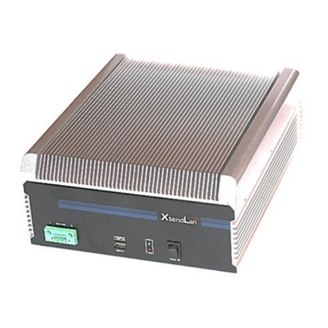
XtendLan TCD-N2600-C2G2-2 User manual

ii
TCD-N2600-C2G2-2
DIN miniPC
User’s Guide

3
Table of Contents
TCD-N2600-C2G2-2 User’s Manual .....................................................................................i
Chapter 1 Introducing the TCD-N2600-C2G2-2 System ........................................................... 1
Overview .................................................................................................................................... 1
Series Comparison Table ......................................................................................................... 2
Layout ......................................................................................................................................... 3
Specifications ............................................................................................................................4
Packing List.................................................................................................................................5
Chapter 2 Hardware Installation.................................................................................................. 7
Before Installation ..................................................................................................................... 7
Removing Covers –Installing Hardware............................................................ 8
I/O Peripheral Connectors ................................................................................ 13
Connecting the DC Power and Power Switch .............................................17
Power and HDD LED Indicator .........................................................................17
Switch and Jumper Setting...............................................................................18
Chapter 3 BIOS Setup.................................................................................................................. 21
Overview ..................................................................................................................................21
BIOS Functions ..................................................................................................... 22
Keyboard Convention .......................................................................................23
Main Setup ...............................................................................................................................24
Advanced Setup ....................................................................................................................25
ACPI settings ........................................................................................................26
CPU Configuration.............................................................................................. 27
USB Configuration ............................................................................................... 29
Intel Fast Flash Standby ..................................................................................... 31
IDE Configuration................................................................................................ 32
Super IO Configuration ......................................................................................34
H/W Monitor ......................................................................................................... 37
Chipset......................................................................................................................................38
Host Bridge ...........................................................................................................39
South Bridge.........................................................................................................41
Boot ...........................................................................................................................................48
4
Security .....................................................................................................................................51
Save & Exit................................................................................................................................53
Chapter 4 Software Installation.................................................................................................. 55
System Driver............................................................................................................................55
WIN XP/7 Driver.............................................................................................................55
VGA Driver................................................................................................................................56
WIN XP/7 Driver.............................................................................................................56
Audio Driver .............................................................................................................................56
WIN XP/7 Driver.............................................................................................................56
LAN Driver (RTL 8111F) ............................................................................................................57
WIN XP/7 Driver.............................................................................................................57
BIOS Flash Utility .......................................................................................................................57
iFFS setup procedure.............................................................................................................58
Watchdog Timer .....................................................................................................................61
Watchdog Timer Setting ............................................................................................. 62
Watchdog Timer Enabled ..........................................................................................63
Watchdog Timer Trigger .............................................................................................64
Watchdog Timer Disabled .........................................................................................64
Digital I/O programming .......................................................................................................65
CANBUS ....................................................................................................................................66
Defined Memory Mapping And Interrupt ............................................................... 66
Example Programming ...............................................................................................67
Chapter 5 Technical Reference ................................................................................................ 69
Trouble Shooting for Post Beep and Error Messages........................................................69
Technical Reference..............................................................................................................72
Physical and Environmental.......................................................................................72
Serial Ports......................................................................................................................73
Appendix...................................................................................................................................... 77
Dimension.................................................................................................................................77

1
Overview
The TCD-N2600-C2G2-2 is an embedded system with Intel® Atom™ N2600 low-
power CPU module inside. This user’s manual provides information on the physical
features, installation, and BIOS setup of the TCD-N2600-C2G2-2.
Built to unleash the total potential of the Intel® Atom™ N2600 Processor, Able to
support 1.6 GHz CPU, this unit supports two 10/100/1000 Base –TX LAN ports, four
USB ports, 2-In/2-Out digital I/O, 1 So-DIMM socket supports up to 2GB DDR3 RAM ,
and a VGA controller.
Each TCD-N2600-C2G2-2 has two ports for I/O communications. One
RS232/RS422/RS485 port and one RS232/RS422/RS485/CAN port are available. The
CAN (Controller Area Network) is a serial bus system especially suited for
networking "intelligent" I/O devices as well as sensors and actuators within a
machine or plant. Characterized by its multi-master protocol, real-time capability,
error correction, high noise immunity, and the existence of many different silicon
components, the CANserial bus system, originally developed by Bosch for use in
automobiles, is increasingly being used in industrial automation.
The TCD-N2600-C2G2-2 is perfect for ATM machines, KIOSK, point-of-sales/point-of-
information, gaming and infotainment, measurement technology, lotteries, and
bankingand small Embedded Control. The unit is only 102 mm (D) X50.4 mm (W)
X145 mm (H).
Chapter 1 Introducing the TCD-N2600-
C2G2-2System

2
Series Comparison Table
Model
TCD-N2600-C2G2-2
System Processor
Intel ® Atom™ N2600 1.6GHZ
S-Chipset
NM10
Memory
204 Pin-DIMM*1
DDR3-800/1066
2GB
Storage
One CFast, SD and
One 2.5’ SATA HDD
Display
VGA/CRT
Watchdog Timer
Yes
Multi I/O
One RS232/RS422/RS485 and
One RS232/RS422/RS485/CAN
USB 2.0
Four
Audio
Ear-Phone
RJ45 LAN port
(10/100/1000 Mbps)
Two Realtek RTL8111F
PCIe Mini Card
One
Operating Temperature
0~+ 50℃(32~122℉)
Storage Temperature
-20~+60℃(4~140℉)
Dimensions (Unit: mm)
50.4(W) x 102 (D) X 145 (H)

3
Layout
ANTENNA POWER
BUTTON
LAN2 2
USB
LAN1
COM1
CRT COM1
HDD
EAR-PHONE
DC IN
POWER
SWITCH
ANTENNA
DC IN
COM2
/
CAN
-
+
D I/O
IN
-
OUT
1
0
+
DC
12~40V
COM2/CAN
DIGITAL I/O
1

4
Specifications
Processor Board –
Intel ® Atom™ N2600 1.6GHZ Low Power Processor with 2GB DDR3-RAM.
I/O Outlets –
Two 10/100/1000 base-TX Ethernet LAN port with RJ45.
One VGA display connector with DB15 and one Audio connector for
Earphone-Out
Four USB ports (2.0) with type A connector
One RS-232/RS422/RS485 and one RS-232/RS422/RS485/CAN port with DB9
2-In and 2-Out Isolated Digital I/O with terminal block
One PCIe Mini card socket modules, especially for WLAN/GPRS module
One DC-In terminal block with power switch and power button
CAN BUS –
The CAN bus using the Philips SJA1000 controller, electrically compatible
with the PCA82C200 stand-alone CAN controller chip
•Full CAN-functionality 2.0 B
•Extended receive buffer (64 byte FIFO)
•16 MHz CAN Control frequency
Storage Bay-
CFast Compact Flash socket for CFast Compact Flash modules
One SATA 2.5" hard disk space
One SD socket supports up to 32GB SDHC (Class 6)
Power requirement –
+9 ~ +32V DC, 1.7A maximum (1.0A typical) with DC 19V input
Dimensions -
102.0mm (D) x 145.0mm (W) x 50.4mm (H)

5
Packing List
Upon receiving the package, verify the following things. Should any of the
mentioned happens, contact us for immediate service.
Unpack and inspect the TCD-N2600-C2G2-2 package for possible
damage that may occur during the delivery process.
Verify the accessories in the package according to the packing list and see
if there is anything missing or incorrect package is included.
If the cable(s) you use to install the TCD-N2600-C2G2-2 is not supplied
from us, please make sure the specification of the cable(s) is compatible
with the TCD-N2600-C2G2-2 system.
The following lists the accessories that may be included in your TCD-N2600-C2G2-2
package. Some accessories are optional items that are only shipped upon order.
One TCD-N2600-C2G2-2 embedded system.
One pack of 2.5” SATA hard disk installation kit with fixed screws.
One 2-pin apartable terminal block.
One 2*3-pin apartable terminal block for isolated digital I/O.
One DIN Rail mounting kit with 2 screws.
One compact disc includes software utility and manual.
Optional:
One pack of half size mini PCIe module adapter kits.( P/N:0606010028G)
FX5311K1 panel back mounting fixers and 2 screws (VESA 75*75).
(P/N:0606010019G)
FX5321K1 2U Rack mounting kit (P/N: 0606010030G)
Note: after you install the TCD-N2600-C2G2-2, it is recommended that you keep
the diskette or CD that contains drivers and document files, and keep the
document copies, or unused cables in the carton for future use.

6

7
This chapter introduces the system connectors & jumper settings, and guides you to
apply them for field application.
Before Installation
Before you install the system, make sure you follow the following descriptions.
1. Before removing the cover, shut down the operation System and disconnect
power switch to off and unplug DC-In cable.
2. Install any connector, Compact Flash, and hard disk is sure that the power is
disconnected or power switch to off from the system. If not, this may damage
the system.
3. The ESD (Electricity Static Discharge) may be created from human body that
touches the board. It may do damage to the board circuit.
Chapter 2 Hardware Installation

8
Removing Covers –Installing Hardware
If you are installing hardware option, you can remove the front and back cover.
The following figure will guide you how to install CFast modules, SD Card, 2.5" HDD
inside and PCIe Mini card the TCD-N2600-C2G2-2 and how to install the TCD-
N2600-C2G2-2 fixers. (Please see the spots circled.)
a. Unscrew front cover and Installing Compact Flash & SDcard
b. Unscrew back cover and Installing Hard Disk
Note: The SD socket supports up to 32GB SDHC (Class 6).

9
b1. Installing Hard Disk
c. Installing Memory: So-DIMM Socket for DDR3 RAM Modules
You may extend additional memory to TCD-N2600-C2G2-2, See as following figure
andrear pictures. The So-DIMM socket supports 1GB to 2GB of DDR3 RAM modules.
Note: Use caution when handling the hard disk to prevent damage to SATA
connector as you inserted hard disk. Be careful with the orientation wheninstalling
connectors.

10
d. Installing PCIe Mini Card Module –Daughter Board
You may extend additional PCIe mini card module and SIM card to TCD-N2600-
C2G2-2. Connect the antenna cable from backside antenna hole to GPRS
module and installing the SIM card to SIM socket. See as following figure.
d1. Installing Half Size Mini PCIe module kit (Optional)
Note: 1. When installing PCIe GPRS Mini card on TCD-N2600-C2G2-2system
these is need the installing the SIM Card to daughter board of system.
2. The insert SIM card into the SIM card socket. Make sure that the SIM card
is properly inserted and that golden contact area on the card is facing
downwards.

11
e.
lnstolling the DIN-Roil fixers or universol fixers on TCD-N2600-C2G2-2
Please refer to the down side figure for installing the TCD-N2600-C2G2-2 with
universal fixers.
e1. TCD-N2600-C2G2-2 Din-Rail

12
2U Rack Mount Kit

13
1
I/O Peripheral Connectors
View from the back side, if you are connecting the monitor, LAN, COM, CAN,
Audio, Digital I/O and USB to the TCD-N2600-C2G2-2. See following figure and a
sidepictures.
ANTENNA POWER
BUTTON
LAN2 2
USB
LAN1
COM 1
CRT COM1
HDD
EAR-PHONE
DC IN
POWER
SWITCH
ANTENNA
DC IN
COM 2
/
CAN
-
+ D I/O
IN
-
OUT
1
0
+
DC
12~40V
COM2/CAN
DIGITAL I/O
1. A VGA (CRT) connector is provided for VGA signals.
DB15
Signal
1
Red
2
Green
3
Blue
13
Hsync
14
Vsync
12
DDC Data
15
DDC Clock
5 & 10
Digital Ground
6,7,8
Analog Ground
Others
Not Used

14
2. Connecting the COM port
The COM1 and COM2 (DB9) are designed for multiple proposes, It’s can select RS-
232/422/485/CAN (The CAN port Only for COM2) by BIOS or jumper setting. The
following tables show the signal connections of these connectors.
COM1 COM2
3. Connecting the CAN-BUS
The CANBUS is use COM2 (DB9) standard connector. The following tables show
the signal connections of this connector.
CAN
6
1
9
5
Note: 1. The CANBUS DB9-pin out conforms to the ISO 11898/2 standard specification.
DB9
RS-232
RS-422
RS-485
1
-DCD
6
-DSR
2
RXD
RX-
485-
7
-RTS
TX-
3
-TXD
RX+
485+
8
-CTS
TX+
4
-DTR
9
-RI/5Vor 12V
5
Ground
Metal
Case Ground
DB-9
CANBUS
Signal
CANBUS
Description
1
N.C
-
6
N.C
-
2
CAN-L
Dominant Low
7
CAN-H
Dominant High
3
CAN-Ground
Isolated Ground
8
N.C
-
4
N.C
-
9
N.C
-
5
Ground
Digital Ground
Case
Case Ground

15
4. Connecting the LAN ports (LAN1&LAN2)
The RJ45 connector with 2 LED’s for LAN. The up LED (orange) indicates data is
being accessed and the down side LED (green) indicates on-line status. (On
indicates on-line and off indicates off-line)
RJ45 connector
8
1
5. Connecting the USB Ports
The TCD-N2600-C2G2-2 supports a four port USB connector. Any USB device can
beattached to USB ports with plug-and-play supported.
1
4
6. Digital I/O Connector
The TCD-N2600-C2G2-2 provides 2-in and 2-out isolated digital I/O, output port is
an open collector, you will need connections external voltage of Digital (+) and
digital (-) connector.
D I/O
Digital I/O
Note: Digital inputs accept DC12~40V Signal with isolated input. Digital outputs
are active-low open collector output, and can drive up to 60V/400mA
maximum.
RJ45
LAN1/2
RJ45
LAN1/2
1
MDI0+
5
MDI2+
2
MDI0-
6
MDI2-
3
MDI1+
7
MDI3+
4
MDI1-
8
MDI3-
USB #1~ #4
Signal
1
USBV
2
USBD-
3
USBD+
4
USBG
DI/O
Signal
Bit Location
IN-1
DGI1
Please refer to
Chapter 4-
Digital I/O -
Software
programming
example
IN-0
DGI0
OUT-1
DGO1
OUT-0
DGO0
+
Digital Voltage
-
Digital Ground

16
7. Connecting the Audio EAR-Phone
EAR-Phone

17
Connecting the DC Power and Power Switch
Power is supplied through an external power DC In. See following figure and a side
pictures.
1. DC Power Connector: Use external 2-pin apartable terminal block.
DC IN -
9V~32V
+
Terminal Block
DC +9V~+32V, 40VA
minimum
2. Power Switch and Power Button: The Power Switch controls the main power
switch, plugging DC into DC power connector then turn on the Power Switch,
when you final installed system hardware device. Pushing the Power button
once will switch the TCD-N2600-C2G2-2 on and off.
ON
OFF
Power Switch: On/Off
Power and HDD LED Indicator
Power button: On/Off
The Power LED is integrated into the power button. The HDD LED’s has two
distinctive statuses: Off for inactive operation and blinking light for activity.
POWER
HDD
Table of contents
Other XtendLan Desktop manuals

XtendLan
XtendLan TC-965 User manual

XtendLan
XtendLan EBF-211-Z3735F-2-32 Owner's manual

XtendLan
XtendLan TC-261 User manual

XtendLan
XtendLan EBF-211-Z3735F-2-32 Owner's manual

XtendLan
XtendLan PTDX5311 User manual

XtendLan
XtendLan TC-800 User manual

XtendLan
XtendLan EBF-231-5I24 User manual

XtendLan
XtendLan TV-850B User manual