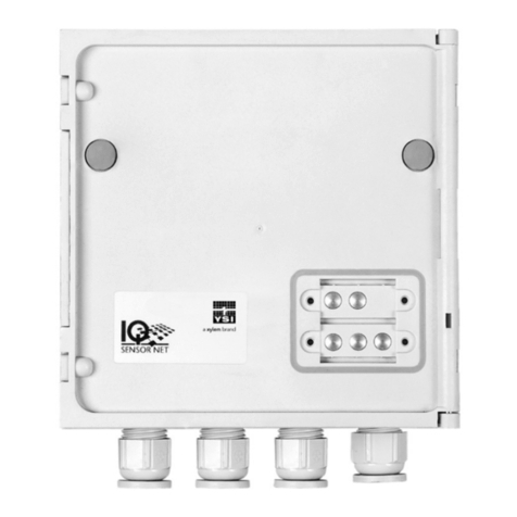
Xylem Aquavar SPD SPD20050 User manual
Other Xylem Control Unit manuals

Xylem
Xylem LOWARA Aquavara IPC User manual

Xylem
Xylem McDonnell & Miller GuardDog RB-122-E User manual
Xylem
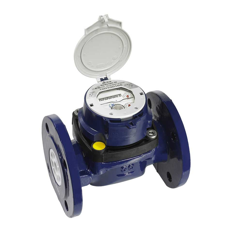
Xylem sensus HRI-Mei FS User manual
Xylem
Xylem FLYGT Pareo DCM 711 User manual
Xylem
Xylem McDonnell & Miller 750B-C3 Series User manual

Xylem
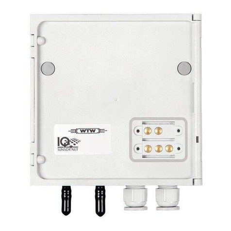
Xylem Hoffman Specialty 792 User manual
Xylem
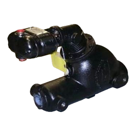
Xylem WTW MIQ/CHV PLUS User manual
Xylem
Xylem McDonnell & Miller SA47-4 User manual

Xylem
Xylem Bell & Gossett Hoffman Specialty 78 User manual

Xylem
Xylem SIRT 868 MHz User manual
Xylem
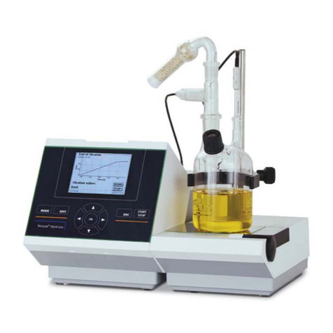
Xylem SI Analytics TITRATOR TitroLine 7500 KF User manual
Xylem
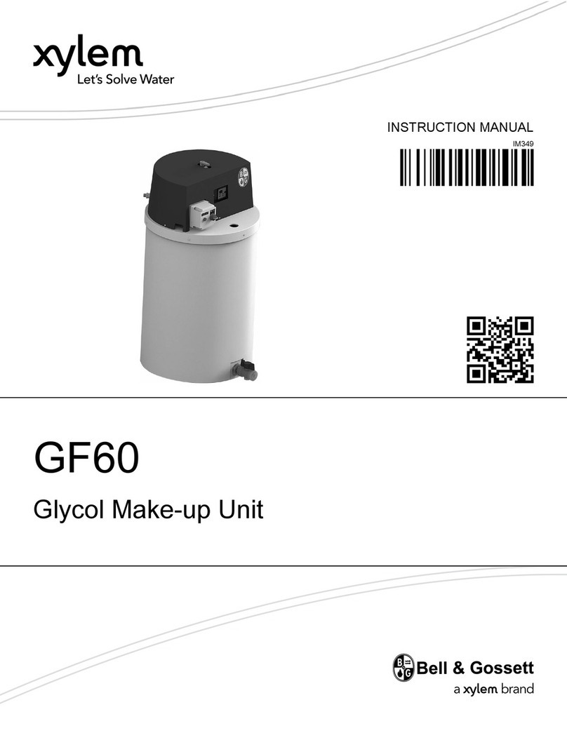
Xylem Bell & Gossett GF60 User manual
Xylem
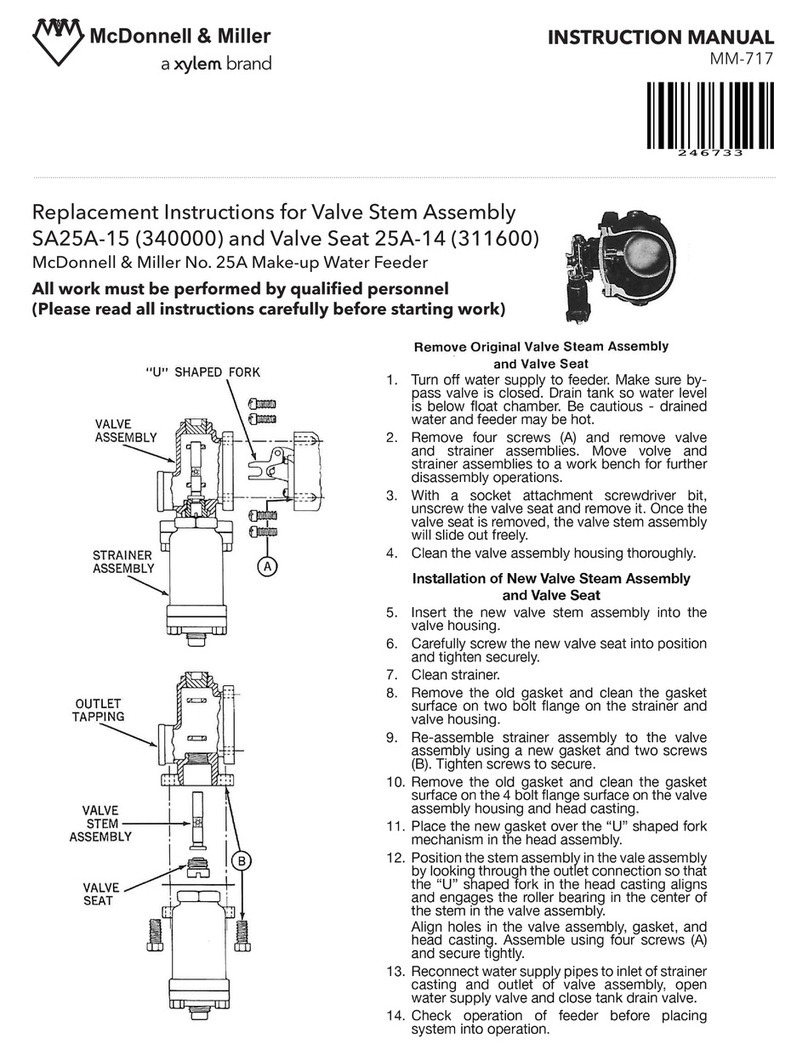
Xylem McDonnell & Miller SA25A-15 Guide
Xylem
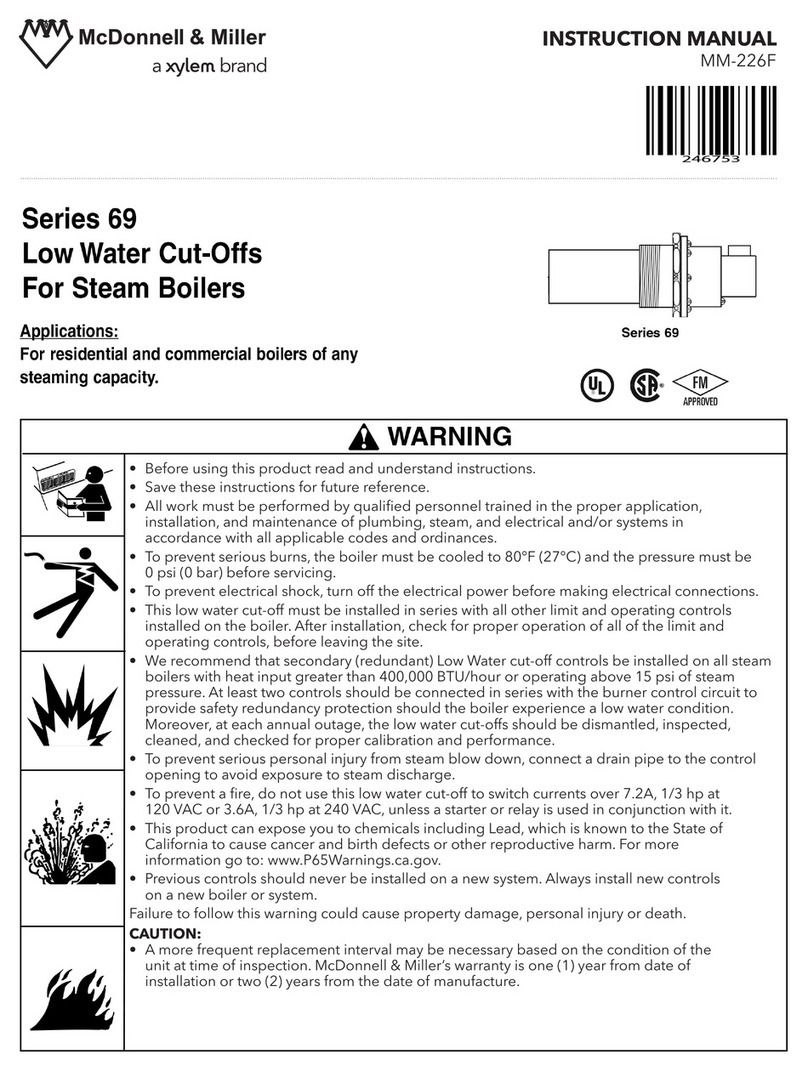
Xylem McDonnell & Miller 69 Series User manual
Xylem
Xylem Lowara Gen Series User manual
Xylem
Xylem FST User manual
Xylem
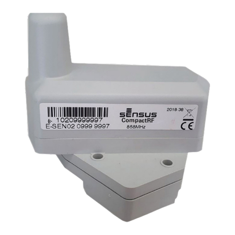
Xylem Sensus CompactRF User manual
Xylem
Xylem Hoffman Specialty 2000 Series User manual
Xylem
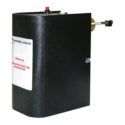
Xylem McDonnell & Miller PSE-800-M User manual
Xylem
Xylem McDonnell & Miller RB-24E User manual
Popular Control Unit manuals by other brands

Festo
Festo Compact Performance CP-FB6-E Brief description

Elo TouchSystems
Elo TouchSystems DMS-SA19P-EXTME Quick installation guide

JS Automation
JS Automation MPC3034A user manual

JAUDT
JAUDT SW GII 6406 Series Translation of the original operating instructions

Spektrum
Spektrum Air Module System manual

BOC Edwards
BOC Edwards Q Series instruction manual

KHADAS
KHADAS BT Magic quick start

Etherma
Etherma eNEXHO-IL Assembly and operating instructions

PMFoundations
PMFoundations Attenuverter Assembly guide

GEA
GEA VARIVENT Operating instruction

Walther Systemtechnik
Walther Systemtechnik VMS-05 Assembly instructions

Altronix
Altronix LINQ8PD Installation and programming manual
