6
Analog
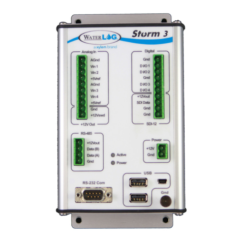
There are four analog input channels labeled Vin1 to Vin4. They are grouped
in sets of two with each set having a common ground and +5Vref terminal
connection. The standard input range for all channels is 0 to 5 volts. The Analog
to Digital converter is highly accurate and can accurately measure low level
(microvolt) signals.
There are two analog ground connection points. In order to preserve signal
integrity the analog section is electrically isolated from the rest of Storm3. Only
analog sensors should be connected to the analog section. Digital sensors are
electrically noisy. If a digital sensor is connected to the analog section or uses an
analog ground the noise from the digital sensor will adversely affect the analog
readings.
The +5Vref output is used for analog sensors requiring a precision reference
voltage. The maximum output current is 10 mA. The Analog to Digital converter
uses this excitation for its reference to provide a ratio-metric relationship for
sensors using this excitation.
+12Vswd The Switched +12 volt excitation is a programmable 12 volt supply who’s settings
are on, off, or on only during a measurement. The default setting is off.
RS-485
A four position terminal block is provided for the RS-485 connection. This
port is primarily used for Modbus communication but can be programmed to
communicate with RS-485 sensors.
Active and Power
LEDs
The Active LED will blink when the system is performing some activity. The Power
LED will blink about every five seconds when proper power has been applied to
the system.
RS-232
The RS-232 port provides a connection to a cellular modem, GOES transmitter,
remote display, or other standard serial sensors and communication equipment. It
can also be configured for Modbus communication.
The port is configured as a Data Terminal Equipment (DTE) device. This means it
will plug directly into a Data Circuit Terminated (DCE) device like a modem, but
will require a NULL modem adaptor and gender changer if connected to a PC
(DTE device).
Digital I/O
The Digital I/O connections can be configured independently as inputs or
outputs. In input mode, the signal has an internal pull up resistor of 47 KOhms.
This allows a switch closure to ground to activate the input which can be
configured as a tipping bucket rain gauge input.
It can also be driven using normal 5 volt logic levels. As an output, a 100 Ohm
protection resistor limits the drive capability. The output will still be about 4 volts
with a load of 10 mA or less.
Get to Know Your Storm3
