www.sensus.com
MD 5000
1. Supplied Material
Each package contains:
• 1iPERLdevice
• manual
• sealings
• optionalconnectionkits
• NRV(ifordered)
2. General Instructions
Pleasereadthisguidepriortoinstalling
iPERL.
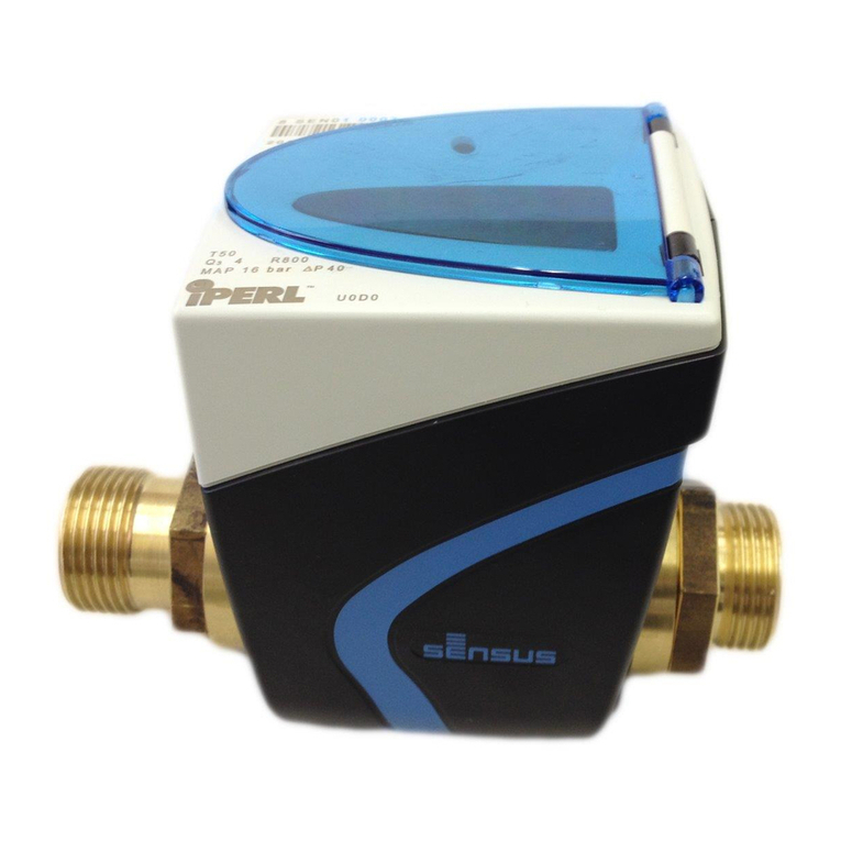
iPERLisameteringendpointdesignedfor
usewithpotablewatersuppliestoresidential,
commercialandindustrialactivities.
iPERLisintendedformaintenance-free
operationforupto15years.
IPERLishermeticallysealedandtherefore
thereisnoservicingofthemeterrequired.
3. Permissible Operating Conditions
• min.waterconductivityrequired:120µS/cm
(25°C)
• Coldwatermeter:from0.1°Cupto50°C
• Pressurestage:PN16
• Mechanicalenvironment:M2(MID)
xedinstallationwithminimumvibration
• Electromagneticenvironmentalclass:E1
andE2(MID)residentialandcommercial
• Protectionclass:IP68
• Climaticenvironment:from-15°Cupto60
°C
4. Installation Requirements
Ensurethatthepipeworkdoesnotintroduce
mechanicalstressesonthemeterbody:
checkingbothalignmentofthepipework
withthethreadedconnectionsanddistance
betweenunionswiththemeterlaylength.
Ifthereismechanicalstressusageofthe
bracketsisrecommended.Whenmounting
iPERLontoanetwork,ensurecontactsurfaces
areevenandcleanandusenewgaskets.
Atalltimesduringinstallationandthereafter
allstatutoryprovisions,regulationsandnorms
havetobefollowed,inparticularwithregardto
healthandsafety(e.g.earthing,bridging,etc.).
Compositematerialsusedarenonconductive.
Torque:tighteniPERLtoaminimumtorque
settingof20Nmandamaximumof30Nm.
1 Installationposition:iPERLhasbeen
designedtooperate,withnoimpacton
metrologicalperformance,inallinstallation
anglesandorientations.
2 PleaseavoidinstallingiPERLasshown
belowasareductionofbatterylifetimecould
occur.
Keepthevalvesclosedwhenthepremises
arevacant.Makesureyouclosebothvalves
beforeandafterthemeterforsafetyreasons
wheninstallationisnotnishedyetorthereis
nowaterconsumptionforalongerperiod,e.g
duetovacantpremises.
iPERLisfreeofanyconstraintforupstreamor
downstreamstraightpipelengths.
Flowdirection:iPERL’smetrological
performanceisindependentofowdirection
andorientationofthemetercanbeselectedto
bestsuittheinstallationconditions.iPERLwill
detectowdirectionwheninstalledandsetthe
directionindicatoraccordingly.
Pressure:pleaseensurethatiPERLstrictly
operateswithinthepressureratingprintedon
themeterbody.
AlliPERLsettingsandfunctionswillbe
automaticallyandcorrectlyactivatedoncethe
owtubeissaturated.
5. Installation Procedure (Volume
registration & Flow direction)
STEP1:
1A:RemoveiPERLfromitspackagingand
locateanyoptionalcomponent(lter,non-
return-valve*(NRV),...)
Incaseyouneedanon-return-valveplease
consider:
3iPERL,DN15,110and115mm:NRV
installationinmeterscrewconnection
4 Allothernominalsizesandlengths:NRV
installationinmeasuringtube
iPERLwilldisplaythefollowingsymbols:
5 NoVolume,noowandthealarmag
(raisedforemptypipe)
1B:InstalliPERLaccordingtothemost
suitableLCDorientation
STEP2:
6 Onceinstalled,opentheupstreamvalveto
llthemeter.Thealarmagdisappearsafter
ashortwhile,thisindicatesthatthemeterhas
detectedwaterinthepipe.
iPERLisnowfullyoperational,althoughin
stand-bymode.Atthispoint,alsotheradio
transmissionisactivatedwhichisindicatedby
aashingradiosymbol.Themeterstartsto
sendoutradiotelegrams.
STEP3:
7Toactivatethe“owdirectiondetection”,
ensureaowabovethethresholdof
3 l/h for DN15
5 l/h for DN20
8 l/h for DN25
12.5 l/h for DN32
20 l/h for DN40
Botharrowsblinktoindicatethemeteris
detectingitsforwardowdirection.After
reachingthethresholdthearrowisset.
Itstartstoaccumulatevolumeintothethree
registersforward,reverseandbillingvolume.
Theowratewillstarttobedisplayedafterthe
rst4hoursofoperation.
Whenthebillingvolumeregisterreachesthe
thresholdof
25l for DN15
40l for DN20
63l for DN25-40
themetertakesthatregisterwiththehigher
volumeaccumulatedastheforwardregister
andxestheowdirection.
Fromthismomentontheowdirectioncannot
bechanged;anyowinthe'wrong'direction
willnowtriggerthealarmagfor'reverseow'
andwillbecountedasreversevolume.
8 Aftertheowdirectionisset,thefunctions
forperformingthehigheranalysis,suchas
dataloggingandleakdetection,become
activeandareassignedtotherespectivedata
elds.
9 IMPORTANT!iPERLdoesnotregisterthe
volumeiftheaveragedowrateisbelow
1 l/h for DN15
1.6 l/h for DN20
2.5 l/h for DN25
4 l/h for DN32
6.4 l/h for DN40
6. iPERL Display and Characters
Afterinstallationissuccessfullycompleted
thedisplayshows:
•Meterreadingandpreselectedunit
•Currentowrateandpreselected
unit
•Flowdirection
•RFactive
Alarmsaredisplayeddirectlyonthedisplay
aftertheLCDself-test:
AL–05Emptypipe
AL–06Magnetictampering
AL–07ReverseFlow
AL–08Brokenpipe/Leakage
Ifanyofthefollowinggraphicsisdisplayed,
pleasecontactyoursupplier:
•Alarmag+AL-xx(except05-08,see
above)
•Lowbatterywarning
•Testmode
7. Disposal
ThisproductcontainsalithiumIonbattery.
Intheinterestofprotectingtheenvironment,
thisbatterymaynotbedisposedinhousehold
wasteafteritsperiodofuse.Thelocal
andnationalregulationsforenvironmental
protectionaretobeconsidered.
Installation Manual
EN DE FR ES
MD5000INT4•0003
1
2
5
6
7
8
9
Graphic Description
Meter Reading
Current owrate
Index units
Flowrate units
Alarm ag
Flow direction
RF active
Low battery warning
Test mode
81241
Lithium
5
←3
4
←
←
*Australiaonly:NRVisalreadypre-installed!
iPERL

