Xylem Jabsco 37045 Series User manual

Model 37045-Series
QUIET - FLUSH
ELECTRIC TOILET
FEATURES
• Very quiet flush cycle - like a household toilet
• Single button flush actuator - with dual function water
level control switch
• Can be plumbed to any pressurized water system
that can provide a 3-1/2 GPM (13.5 LPM) flow rate
• Water control solenoid valve with anti-siphon breaker
to prevent contamination of potable water supply
• White vitreous china bowl available in compact or
comfortable household size
• Baked enamel seat & cover - soft close seat option
available on regular bowl models
• High capacity waste macerator and bowl discharge
pump
SPECIFICATIONS
PORTS Toilet Inlet 3/4" (19mm) Hose Barb
Toilet Outlet 1" (25mm) Hose Barb
MOTOR Meet U.S.C.G. Regulation
& SWITCH 183.410 and ISO 8846 MARINE
for Ignition Protection.
WATER 1-2 Quarts (Litres) per Flush
CONSUMPTION
VARIATIONS AVAILABLE
MODEL NO. DESCRIPTION
37045-3092 Compact Bowl 12V
37045-3094 Compact Bowl 24V
37045-4092 Regular Bowl 12V
37045-4192 Regular Bowl 12V, Soft Close Seat/Lid
37045-4094 Regular Bowl 24V
37045-4194 Regular Bowl 24V, Soft Close Seat/Lid
OPERATION
The Quiet-Flush toilet provides both quiet operation and
user control of water levels in the toilet bowl. A single
large push button switch provides a simple flush mode
by activating both the rinse water supply and the macer-
ator discharge pump simultaneously. An additional rocker
switch offers independent control of the rinse water supply
and discharge pump separately so the bowl water level
can be easily raised or lowered by the user. This provides
a method of minimizing water use, when desired, as well
as a means of raising the water level in the bowl when
appropriate for user comfort. It also allows for complete
evacuation of the bowl water while underway in rough
sea conditions.
INSTALLATION
PLUMBING
The toilet can be plumbed to any pressurized water sys-
tem that can provide a minimum of 3-1/2 GPM (13.5
LPM). This may be a fresh water system including the
vessel’s potable water system or a washdown system
utilizing either fresh or salt water. However, it must be
connected to a pressurized system that normally re-
mains on at all times while the vessel is in use.
To make the water connection, shut off the water system
pump and open one of the systems faucets or fixtures to
drain the pressure from the system. Select an appropri-
ate tee type fitting that can be installed in the existing
pressurized water system and will provide a 1/2"
(13mm) hose barb to feed water to the toilet. Install the
tee fitting at a location on the pressurized water system
that provides convenient connection to the toilet’s
solenoid valve/ siphon breaker assembly. If the toilet is
being connected to the vessel’s fresh water system and
the vessel may be connected to an unregulated city
water supply, it is recommended that a valve be installed
in the toilet water supply line ahead of the solenoid
valve/siphon breaker to regulate the flow rate of
incoming pressurized city water.
Model 37045-Series

INSTALLATION (continued)
PLUMBING
The solenoid valve/siphon breaker should be positioned
a minimum of six inches above the hose connection at
the back of the toilet bowl (at all angles of heel and trim)
and located as close to the toilet as possible. It should be
located where an occasional drop or two of water from
the siphon breaker will not adversely affect nearby equip-
ment or supplies. It must be installed in a vertical position
with the hose barb connections pointing down. The sole-
noid valve/siphon breaker bracket should be secured to
a solid mounting surface with four screws. If the valve
assembly is attached to a wood surface, 3/8" (10mm)
long screws are generally adequate to support the
weight of the valve assembly. If desired, the valve
assembly may be installed inside a cabinet or locker to
conceal it from view of the vessel’s occupants. To provide
a clean sanitary appearance inside the head area, a six
foot section of smooth white hose is provided with the toi-
let to connect the toilet bowl spud fitting to the siphon
breaker outlet hose barb.
The solenoid valve inlet hose barb is then connected
with 1/2" (13mm) reinforced vinyl hose suitable for
pressurized water to the tee fitting installed in the water
system line. All pressurized water system connections
should be secured with stainless steel band type hose
clamps. The 3/4" hose connecting the siphon breaker to
the bowl should be secured with a band clamp at the
siphon breaker to prevent it from being accidentally
dislodged but generally does not need a hose clamp to
secure it to the bowl spud fitting unless desired for added
security.
The discharge port includes a 1" (25mm) hose barb and
should be plumbed with 1" (25mm) hose to an on board
holding tank or, if appropriate, to an overboard discharge
through hull. A 1" (25mm) to 1-1/2" (38mm) barbed hose
adapter is provided to adapt a 1" (25mm) discharge hose
W
!
to 1-1/2" (38mm) hose, if desired. The discharge plumb-
ing should be kept as short as possible and bends in the
discharge hose should be kept to a minimum.
If the toilet is below the water line and is plumbed to an
overboard discharge through hull, the discharge
plumbing must include a vented loop positioned so it
remains above the water line at all angles of heel and
trim. Total discharge head should not exceed 4 feet
(1.2m). To retain water in the bowl, the discharge hose
should be looped upward about eight to ten inches
above the base of the toilet and as near to the toilet as
can be practically accomplished without creating an
unsightly plumbing situation.

RED
BROWN YELLOW
BROWN
YELLOW
RED
RED
RED
BROWN
YELLOW
To Waste Pump
Positive (Orange)
Motor Lead
To Solenoid
Valve/Siphon
Breaker
To Positive
WIRING DIAGRAM
mm) DIA
mm) DIA
TEMPLATE
ELECTRICAL SPECIFICATIONS
Amp Fuse Wire Size Per Feet Of Run*
Voltage Draw Size 0'-10' 10'-15' 15'-25' 25'-40' 40'-60'
12 Vdc 10 25 #16 #14 #12 #10 #8
24 Vdc 5 15 #16 #16 #16 #14 #12
* Length of run is total distance from power source to product and back to ground.
ELECTRICAL
The electrical wiring should be independent of all other
accessories. It should be made with marine grade
copper stranded wire of the gauge specified in the
electrical specifications chart. Make all wire connections
with mechanical locking type connectors (crimp type butt
connectors and terminals). Ensure the circuit is protect-
ed by a proper sized fuse or circuit breaker determined
from the electrical specifications chart. Secure all wires
to a solid surface approximately every eighteen inches
(1/2m) along their entire length of run.
Wire the switch panel to the solenoid valve/siphon break-
er and toilet pump assembly as per the following wiring
diagram. Select a location for the switch panel that is
convenient to the toilet user and will also allow access to
run the wires from the switch panel to both the toilet’s
motor and the solenoid valve/siphon breaker as well as
from the electrical power source to the switch panel. The
red lead from the panel should be connected to an over-
current protected positive power source. Connect the
brown lead from the panel to the waste pump positive
(orange) motor lead. Connect the black waste pump
motor lead to battery negative. Connect the yellow lead
from the panel to a solenoid valve terminal. Connect the
remaining solenoid valve terminal to battery negative.
The solenoid valve is not polarity sensitive.
To install the switch panel, drill two 1-3/4" (45mm)
diameter holes (slightly over-lapping) through the select-
ed switch mounting surface per the attached template.
Ensure the template is oriented correctly because it is
not symmetrical. Also, drill four appropriate sized holes
for the fasteners selected to secure the switch panel to
its mounting surface.

SERVICE
The Jabsco Quiet-Flush Toilet does not require routine
maintenance other than occasional cleaning to maintain
a hygienic sanitary condition. Clean toilet with mild
nonabrasive cleaners without strong aromatics. Cleaners
having high concentrations of aromatics such as pine
scented concentrated cleaners and strongly scented
degreaser concentrates can cause the pump’s seal to
swell and may contribute to a premature seal leak.
The toilet has no wearing parts that need periodic
replacement other than the shaft seal which, under
normal conditions, should provide several years of
service before needing replacement. The seal only
requires replacement if signs of leakage are noticed
under the seal housing positioned between the motor
and toilet base assembly.
Notice: Before performing any service, disconnect the
power supply to the toilet and take precaution to ensure
it is not reconnected until the service is complete. Also,
pump all water from the toilet bowl and if connected to an
overboard discharge, close the discharge seacock.
To replace the shaft seal, snap off the white motor cover
and remove the pump assembly by removing the four
screws with lock washers that secure it to the toilet base.
Carefully slide the pump assembly from the base
ensuring the macerator housing also slides out of the
base with the pump.
The pump chopper will engage the macerator housing
and it may be necessary to gently tap the chopper
against the macerator housing to free it from the base.
Prevent the motor shaft from turning by inserting a
screwdriver in the shaft slot at the rear of the motor and
unscrew the nut retaining the chopper blade. Remove
the chopper and macerator housing from the motor
shaft. Remove the O-ring from the O-ring groove around
the outer diameter of the seal housing. With an allen
wrench, loosen the centrifugal impeller set screw and
slide the impeller off the shaft. Remove the two screws
that secure the seal housing to the motor and slide the
housing off the motor shaft. Remove the two seal wash-
ers from under the head of each of the two seal housing
retainer screws. With a pair of needle nose pliers grasp
the shaft seal and pull it from the seal housing. Clean all
parts and inspect for damage.
Lubricate the OD of the new seal with a small amount of
water and press it into the seal bore with the seal’s lip
facing the threaded end of the shaft. Do not use the
stainless steel star retaining washer supplied with the
seal. Lubricate the ID of the seal and the motor shaft with
a small amount of water resistant grease. Ensure the
slinger is properly positioned on the motor shaft next to
the motor and slide the seal housing onto the motor shaft
until it is against the motor end bell. Position a new plas-
tic seal washer under the head of each of the flat head
seal housing retainer screws and secure the seal hous-
ing to the motor. Slide the centrifugal impeller on the
motor shaft positioning it about 1/32" (1mm) from the
seal housing and secure it to the shaft with the set screw.
Rotate the impeller to ensure it does not rub on the seal
housing.
Slide the macerator housing over the motor shaft, place
the lock washer on the end of the shaft and screw the
chopper onto the shaft. Tighten the chopper while hold-
ing the motor shaft at the rear of the motor. Position a
new O-ring in the seal housing O-ring groove (it may be
retained in the groove with a small amount of grease).
Slide the pump assembly into the toilet base ensuring
the macerator housing is properly positioned within the
base. The cut-out in the side of the macerator housing
must align with the discharge port in the base (the mac-
erator housing is keyed so it will only go in when proper-
ly positioned).Ensuring the O-ring is still properly posi-
tioned in the O-ring groove in the seal housing, place the
pump assembly against the base and secure it in place
with the four screws and lock washers. Replace the white
motor cover by snapping it down over the pump motor.
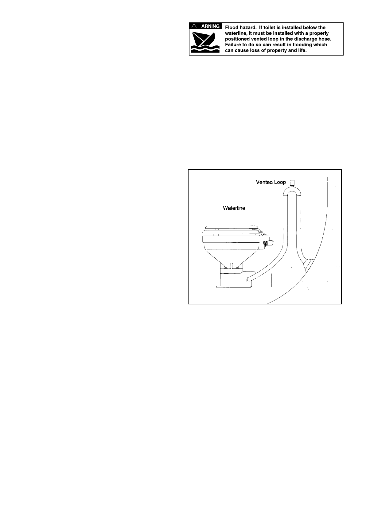
W
!

PARTS LIST
Qty. Part
Key Description Req. Number
1. Seat & Cover
Note - 2016 models identified with Jabsco logo on top of bowl.
Compact 1 29097-1000
Regular (Pre 2018) 1 29127-1000
Regular (2018 onwards) 1 58104-1000
Soft Close (2018 onwards) 1 58104-2000
2. Bowl
Compact 1 29096-1000
Regular 1 29126-1000
3. Hinge Set (1 PAIR)
Compact (ALL VARIANT) 1 29098-1000
Regular (Pre 2018) 1 29098-2000
Regular (2018 onwards) 1 58105-1000
Soft Close (2018 onwards) 1 58105-2000
3 & 4 Bowl Spud & Intake Elbow 1 29048-0000
& O-ring
5 Hose, 6 feet 1 29035-1031
6 Motor Cover † 1 37042-1000
7 Bowl Installation Hardware 1 18753-0637
7A Nut Cap** 4
7B Hex Nut** (Two places) 8
7C Washer, Stainless Steel** 4
7D Washer, Plastic** 4
7E Washer, Starlock** 4
7F Phillips Head Screw** 4
8 Bowl O-Ring Seal 1 44101-1000
9 Base Assembly** 1 37004-1000
10 1-1/2" Adapter, Discharge Port 1 98023-0080
11 Joker Valve* ** 1 44106-1000
12 1" Discharge Port** 1 44107-1000
13 Screw** 3 96050-0568
14 Chopper Plate with Lock Nut † 1 37056-1000
15 Macerator Housing † 1 37014-0000
16 Centrifugal Impeller † 1 37006-0000
Qty. Part
Key Description Req. Number
17 Set Screw † 1 91084-0320
18 O-ring* † 1 43990-0066
19 Seal* † 1 1040-0000
20 Screw † 2 91010-0144
21 Washer, Plastic* † 2 35445-0000
22 Seal Housing † 1 37043-1000
23 Lock Washer #10, Stainless Steel †4
24 Screw † 4 91027-0011
25 Slinger † 1 6342-0000
26 Motors:
Motor - 12 Volt † 1 18753-0554
Motor - 24 Volt † 1 18753-0555
27 Solenoid
24V 1 37038-1024
Valve & Siphon Breaker
12 Volt 1 37038-1012
28 Switch Panel 1 37047-2000
29 Screw Covers (3/kit) 1 37003-0000
Service Kit 90197-0000
Motor & Pump Assembly
12 Volt 37072-0092
24 Volt 37072-0094
* Parts Supplied with Service Kit.
** Parts included with base 37004-1000.
† Parts included in Motor & Pump Assembly.
EXPLODED VIEW

12/07
AL¼ - 200 Self Priming Flexible Impeller Pump
Performance
Parts List
Dimensions in mm (inches)
AL¼ - 200 Series
Note : Performance shown is for a new pump, pumping water at
20ºC, performance may vary by up to 15%. Consult
factory for performance of alternative impeller compounds.
Key Description Part Number
A
Impeller Kit
(Contains Impeller (X),
O-Ring (X))
B
End Cover Kit
(Contains End Cover (X),
Screws (X), O-Ring (X))
C
Shaft Kit
(Contains Shaft (X),
Bearings (X), Retaining
Rings (X & X), Dust Shield
(X))
D
Service Kit
(Contains Impeller (X),
O-Ring (X), Mechanical
Seal (X), End Cover
Screws (X))
E
Seal Kit
(Contains Mechanical Seal
(X), O-Ring (X), Support
Washer (X))
Warranty: All products of the company are sold and all services of the company are offered subject to the company’s warranty and terms and conditions of sale, copies of which will be furnished upon request.
The information provided herein is for guidance only, it does not constitute a guarantee of the performance or specification of any individual product or component.
©Copyright 2003 ITT Industries 43000-0789
UK
Xylem
Bingley Road, Hoddesdon
Hertfordshire EN11 0BU
Tel: +44 (0)1992 450145
Fax: +44 (0)1992 467132
USA
Xylem
100 Cummings Center Drive
Suite 535-N, Beverly, MA 01915
Tel: +1 978 281-0440
Fax: +1 978 283-2619
ITALY
Xylem
Via Tommaseo, 6
20059 Vimercate, Milano
Tel: +39 039 685 2323
Fax: +39 039 666 307
GERMANY
Xylem
Oststrasse 28
22844 Norderstedt
Tel: +49-40-53 53 73-0
Fax: +49-40-53 53 73-11
JAPAN
Xylem
3-21-10, Shin-Yokohama
Kohoku-Ku, Yokohama, 222-0033
Tel: +81-045-475-8906
Fax: +81-045-477-1162
www.xyleminc.com
Warranty: All products of the company are sold, and all services of the company are offered subject to the company’s warranty and terms of sale, copies of which will
be furnished upon request. Details correct at time of printing. We reserve the right to change specifications without prior notice.
© Copyright 2017 Xylem Inc. Jabsco is a trademark of Xylem Inc. or one of its subsidiaries. 43000-0789 Rev: B
43000-0618 Rev: F
© Copyright 2006, ITT Industries Printed in U.S.A. All Rights Reserved Form: 43000-0618 Rev. C 11/2006
1 Dia
(25)
4
(102)
6 (152)
7-1/8 (181)
8-3/8 (213)
C Overall Width
B
F
D
E
5/16
(8)
3-1/8
(79)
A
9-1/2
(242)
12-7/8
(327)
3-3/4
(96)
5-3/4
(146)
2 Leads – 72 Long
(1830)
DIMENSIONAL DRAWING
Inches (Millimetres)
ABCD E F
Compact Size Bowl 3-2/8 (83) 14 (355) 13-1/8 (333) 16-3/8 (415) 9-7/8 (250) 6-7/8 (175)
Household Size Bowl 4-2/8 (108) 14-3/8 (365) 14-3/4 (375) 18-7/8 (480) 10-5/8 (270) 8-2/8 (210)
THE PRODUCTS DESCRIBED HEREIN ARE
SUBJECT TO THE JABSCO ONE YEAR LIMITED
WARRANTY, WHICH IS AVAILABLE FOR YOUR
INSPECTION UPON REQUEST.
www.jabsco.com
U.S.A.
Jabsco
666 E. Dyer Rd.
Santa Ana, CA 92705
Phone: 714.557.4700
Fax: 714.628.8478
UNITED KINGDOM
Jabsco
Bingley Road, Hoddesdon
Hertfordshire EN11 OBU
Tel: +44 (0) 1992 450145
Fax: +44 (0) 1992 467132
CANADA
Fluid Products Canada
55 Royal Road
Guelph, Ontario N1H 1T1
Tel: 519 821.1900
Fax: 519 821.2569
JAPAN
NHK Jabsco Company Ltd.
3-21-10, Shin-Yokohama
Kohoku-Ku, Yokohama, 222
Tel: 045.475.8906
Fax: 045.475.8908
GERMANY
Jabsco GmbH
Oststrasse 28
22840 Norderstedt
Tel: +49-40-53 53 73 -0
Fax: +49-40-53 53 73 -11
ITALY
Jabsco Marine Italia
Via Tommaseo, 6
20059 Vimercate, Milano
Tel: +39 039 685 2323
Fax: +39 039 666 307
XYLEM LIMITED WARRANTY WARRANTS THIS PRODUCT TO BE FREE OF DEFECTS AND
WORKMANSHIP FOR A PERIOD OF (X) YEARS. THE WARRANTY IS EXCLUSIVE AND IN LIEU OF
ANY AND ALL OTHER EXPRESS OR IMPLIED WARRANTIES, GUARANTEES, CONDITIONS OR
TERMS OF WHATEVER NATURE RELATING TO THE GOODS PROVIDED HEREUNDER, INCLU-
DING WITHOUT LIMITATION ANY IMPLIED WARRANTIES OF MERCHANTABILITY AND
FITNESS FOR A PARTICULAR PURPOSE, WHICH ARE HEREBY EXPRESSLY DISCLAIMED
AND EXCLUDED. EXCEPT AS OTHERWISE PROVIDED BY LAW, BUYER’S EXCLUSIVE REMEDY
AND SELLER’S AGGREGATE LIABILITY FOR BREACH OF ANY OF THE FOREGOING WARRAN-
TIES ARE LIMITED TO REPAIRING OR REPLACING THE PRODUCT AND SHALL IN ALL CASES BE
LIMITED TO THE AMOUNT PAID BY THE BUYER HEREUNDER. IN NO EVENT IS SELLER LIABLE
FOR ANY OTHER FORM OF DAMAGES, WHETHER DIRECT, INDIRECT, LIQUIDATED, INCIDEN-
TAL, CONSEQUENTIAL, PUNITIVE, EXEMPLARY OR SPECIAL DAMAGES, INCLUDING BUT NOT
LIMITED TO LOSS OF PROFIT, LOSS OF ANTICIPATED SAVINGS OR REVENUE, LOSS OF
INCOME, LOSS OF BUSINESS, LOSS OF PRODUCTION, LOSS OF OPPORTUNITY OR LOSS OF
REPUTATION. THIS WARRANTY IS ONLY A REPRESENTATION OF THE COMPLETE LIMITED
WARRANTY.
FOR A DETAILED EXPLANATION, PLEASE VISIT US AT www.xylemflowcontrol.com/support/,
CALL OUR OFFICE NUMBER LISTED, OR WRITE A LETTER TO YOUR REGIONAL OFFICE.
43000-0618 Rev: F 12/2017
This manual suits for next models
6
Table of contents
Other Xylem Toilet manuals

Xylem
Xylem Jabsco 37010 Series User manual

Xylem
Xylem Jabsco Lite Flush User manual

Xylem
Xylem JABSCO 37245 Series User manual

Xylem
Xylem JABSCO 29120-5000 User manual

Xylem
Xylem JABSCO Twist'N'Lock COMPACT 29090-3000 User manual

Xylem
Xylem Jabsco 37010 Series User manual

Xylem
Xylem JABSCO 37075 Series User manual

Xylem
Xylem JABSCO Quiet Flush E2 Installation instructions