Xylem JABSCO 37245 Series User manual

QUIET-FLUSH
ELECTRIC TOILET
FEATURES
• Very quiet flush cycle - like a household toilet
• Single button flush actuator - with dual function water
level control switch
• Supplied with PAR-MAX 4 self-priming pump to provide
sea water or lake water to rinse the toilet bowl
• White vitreous china bowl available in compact or
comfortable household size
• Baked enamel seat & cover
• High capacity waste macerator and bowl discharge
pump
S ECIFICATIONS
orts: PAR-MAX 4 Pump and Toilet
Inlet 3/4"Hose Barb
Outlet 1"Hose Barb
Motor Pump and Toilet meet U.S.C.G.
& Switch: Regulation 183.410 and ISO 8846
Marine for Ignition Pro tec tion.
Water 1-2 Quarts (Litres)/Flush
Consumption:
VARIATIONS
Model Number Description
37245-0092* Compact Size Bowl, 12 Volt EMC
37245-0094* Compact Size Bowl, 24 Volt EMC
37245-1092* Household Size Bowl, 12 Volt EMC
37245-1094* Household Size Bowl, 24 Volt EMC
*This model is Marked and complies with EN50081-1 for
suppression of electro-magnetic interference.
O ERATION
The Quiet-Flush toilet provides both quiet operation and
user control of water levels in the toilet bowl. A single
large push-button switch provides a simple flush mode
by activating both the rinse water supply and the macer-
ator discharge pump si mul ta neous ly. An additional rock-
er switch offers independent control of the rinse water
supply and discharge pump separately so the bowl
water level can be easily raised or lowered by the user.
This pro vides a method of min i miz ing water use, when
desired, as well as a means of raising the water level in
the bowl when appropriate for user comfort. It also
allows for complete evac u a tion of the bowl water while
un der way in rough sea conditions.
Model 37245-Series
MODEL 37245-SERIES

INSTALLATION
The 37245-Series Quiet Flush Toilet is com plete with a
dedicated PAR-MAX 4 pump to provide either sea or
lake water to rinse the toilet bowl when flushing the toi-
let. This pump is intended to be located remotely from
the toilet but will function best if the distance from the toi-
let is kept to a min i mum. Because it is self-priming, it
may be located above the vessel’s waterline. It must be
installed with the Pumpgard strainer (pro vid ed with the
toilet) located somewhere in the inlet plumbing to the
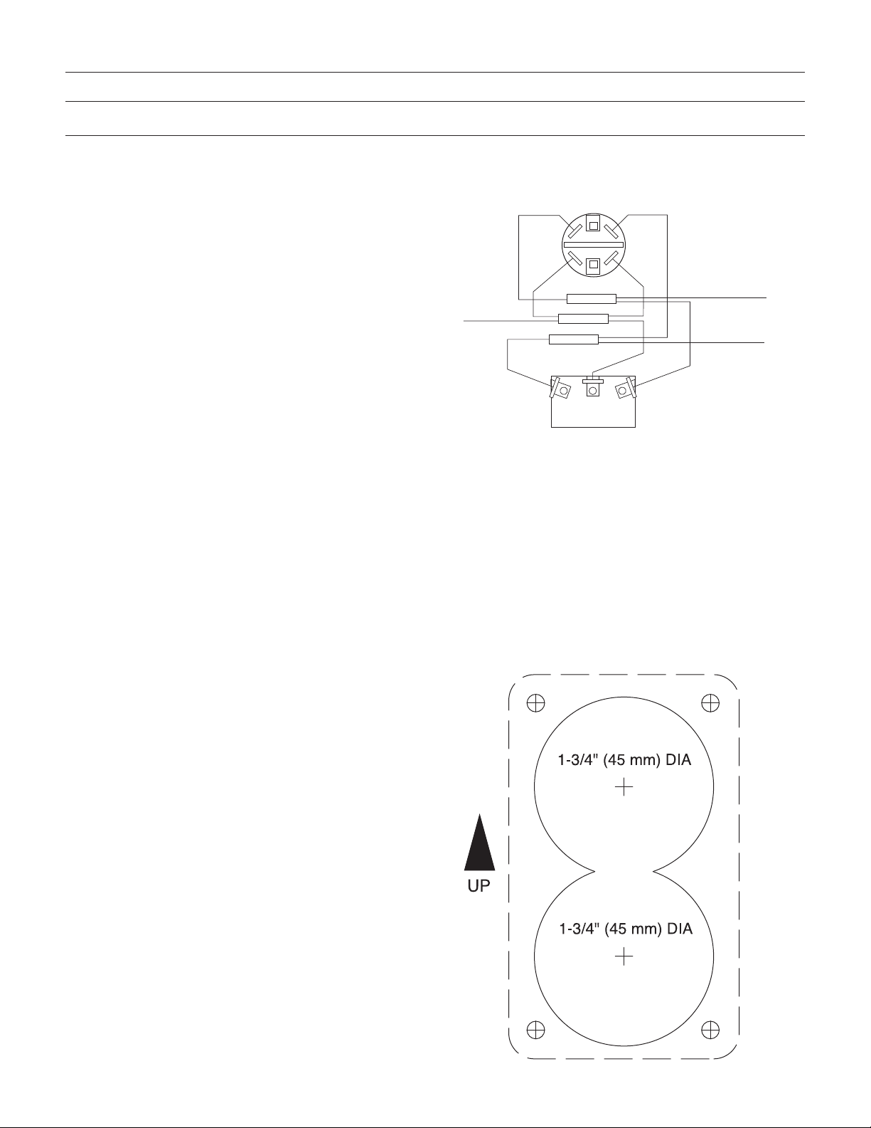
pump. The toilet also includes a multi-function flush con-
trol which should be installed in a bulkhead location that
is convenient to the toilet and allows access for wiring to
run from the power source and to both the toilet dis-
charge pump and the PAR-MAX rinse water pump.
Install the toilet seat and lid assembly on the china bowl
with the fasteners provided and position the toilet in its
desired location. When locating the toilet, ensure there is
adequate clearance above and to the rear of the bowl so
the seat and lid assembly can rotate slightly past vertical
so it will remain up when lifted. It is all right to rotate the
waste pump assembly under the china bowl to provide
clearance from possible ob struc tions, if desired. This
can be accomplished by re mov ing the four white plastic
hex head caps from the nuts at the base of the china
bowl and removing the four machine screws and nuts
that secure the china bowl to the base. The base can
then be reattached to the bowl at any position in 90º in -
cre ments. Once the exact position for the toilet has been
de ter mined, mark the location of the four base at tach -
ment holes on the toilet mount ing sur face. De ter mine the
best toilet at tach ment meth od using 5/16"(8 mm) fas-
teners (either ma chine screws for through bolting or lag
screws for topside at tach ment) and drill the ap pro pri ate
size holes for the fasteners being used. If securing the
toilet with lag screws into a plywood underlayment below
fi ber glass, be sure to drill a hole through just the fi ber -
glass layer large enough to allow clear ance for the screw
threads and shank to avoid crack ing the fi ber glass.
The PAR-MAX pump should be mounted to a solid
mounting surface. It should be secured with four fas ten -
ers through the rubber grom mets that snap into the
pump’s base. Do not over-tighten the mounting screws
and crush the grommets such that they will not absorb
vibration. The pump may be mounted in any position;
how ev er, if mounting it to a vertical surface it should be
oriented so water dripping from a loose port con nec tion
will not drip down on the motor. Plumbing runs should be
kept as short and straight as possible. All plumbing
should be com plet ed with quality 3/4"(19 mm) hose that
will not collapse or kink. Route the inlet hose from a 3/4"
(19 mm) through hull and seacock fitting located well
below the waterline (and well forward of any discharge
through hulls, if in stalled) to the pump inlet port. Ensure
the inlet hose passes through an accessible location
(pref er a bly above the vessel’s waterline) that will allow
for the installation of the Toilet Pumpgard strainer where
it can be pe ri od i cal ly inspected and cleaned of debris.
The Pump gard strainer should be secured with two fas-
teners to a solid mounting surface with the flow arrow
pointing towards the pump. The inlet hose should be cut
and each end attached to the strainer’s ports. The hose
from the strainer’s dis charge port must con nect with the
PAR-MAX pump’s inlet port. Provided with the toilet is a
six foot length of smooth white aes thet i cal ly pleas ing
hose to connect to the back of the toilet bowl and be
routed out of the head area. Ideally, the PAR-MAX pump
should be located so this length of hose can be con nect -
ed directly to the pump’s discharge port avoiding an
additional splice to the hose lead ing from the pump to
the back of the toilet bowl. If this is not practical, acquire
a 3/4"(19 mm) barb to barb hose mender and splice the
white hose to the supply hose from the discharge port of
the pump.
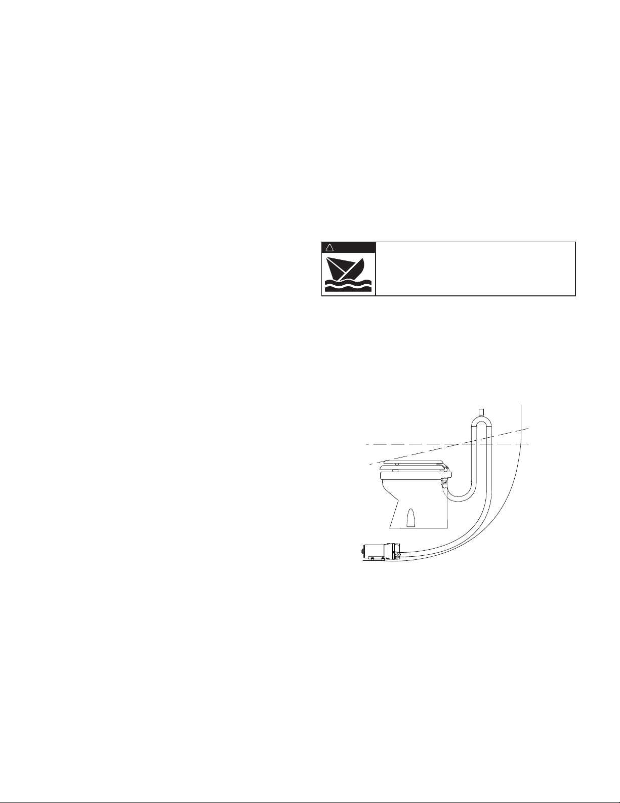
If the toilet is installed below the vessel’s wa ter line, in
order to prevent a siphon action from filling the toilet, a
properly positioned vented loop fitting must be installed
between the PAR-MAX pump and the back of the toilet
bowl. The vented loop fitting must be secured in a loca-
tion that remains at least 6-8 inches (15-20 cm) above
the waterline at all angles of heel and trim (see diagram).
The toilet discharge port is sized for 1"(25 mm) hose.
The discharge hose should be a quality grade re in forced
hose suitable for waste ap pli ca tions. Route the dis -
charge hose to the hold ing tank in the most direct way
with as few bends as possible. To retain some water in
the bowl, it is best to loop the discharge hose up about
8-10 inches (15-20 cm) as close to the toilet as practical
then on to the holding tank. It is best to avoid any dips or
low spots in the dis charge plumbing that can act as
water traps and collect waste. If this occurs, waste can
solidify and cause a discharge blockage.
If the toilet is plumbed to an over board discharge, and is
below the vessel’s waterline, the discharge plumbing
must include a properly positioned vented loop. The
vented loop fitting must be secured in a location that
Flood hazard. If toilet is installed below the
waterline, it must be installed with a properly
positioned vented loop in the discharge hose.
Failure to do so can result in flooding which
can cause loss of property and life.
WARNING
!
Waterline
Vented Loop
Heeled Waterline
2

3
remains at least 6-8 inches (15-20 cm) above the wa ter -
line at all angles of heel and trim. The maximum dis -
charge head without a notable decrease in pump per for -
mance is four feet (1.3 M).
ELECTRICAL
The elec tri cal wiring should be in de pen dent of all other
ac ces so ries. It should be made with ma rine grade cop -
per strand ed wire of the gauge spec i fied in the elec tri cal
spec i fi ca tions chart. Make all wire con nec tions with
me chan i cal lock ing type con nec tors (crimp type butt
connectors and ter mi nals). En sure the circuit is protect-
ed by a proper sized fuse or circuit breaker de ter mined
from the electrical spec i fi ca tions chart. Secure all wires
to a solid surface approximately every eigh teen inches
(1/2 M) along their entire length of run.
Wire the switch panel to the PAR-MAX rinse pump and
toilet waste pump as per the following wiring diagram.
The brown lead from the control panel connects with the
waste pump orange (positive) motor lead. The yellow
lead from the control panel connects with the PAR-MAX
rinse water pump orange (positive) motor lead. The
black motor lead from each pump must be connected to
battery negative. Select a lo ca tion for the switch panel
that is con ve nient to the toilet user and will also allow
access to run the wires from the switch panel to both the
toilet’s waste pump motor and the PAR-MAX pump as
well as from the electrical power source to the switch
panel. To install the switch panel, drill two 1-3/4"(45 mm)
di am e ter holes (slight ly over-lapping) through the se lect -
ed switch mounting surface per the at tached tem plate.
En sure the template is oriented correctly because it is
not symmetrical. Also, drill four ap pro pri ate sized holes
for the fas ten ers se lect ed to secure the switch panel to
its mounting surface.
WIRING DIAGRAM
RED
BROWN YELLOW
BROWN
YELLOW
RED
RED
RED
BROWN
YELLOW
ELECTRICAL S ECIFICATIONS
AM FUSE WIRE SIZE ER FEET OF RUN*
VOLTAGE DRAW SIZE 0'-10' (0 M-3 M) 10'-15'(3 M-4.6 M) 15'-25'(4.6 M-7.6 M) 25'-40'(7.6 M-12.2 M) 40'-60'(12.2 M-18.3 M)
12 Vdc 10 25 #16 (1.5 mm2) #14 (2.5 mm2) #12 (4 mm2) #10 (6 mm2) #8 (10 mm2)
24 Vdc 5 15 #16 (1.5 mm2) #16 (1.5 mm2) #16 (1.5 mm2) #14 (2.5 mm2) #12 (4 mm2)
* Length of run is total distance from power source to product and back to ground.
To PAR-MAX
Pump Positive
(Orange) Motor
Lead
To Waste Pump
Positive (Orange)
Motor Lead
To Positive
TEM LATE

4
WASTE UM SERVICE
The Jabsco Quiet-Flush Toilet does not require routine
maintenance other than occasional cleaning to main tain
a hy gien ic sanitary condition. Clean toilet with mild
non-abrasive cleaners without strong aromatics. Clean -
ers having high concentrations of aromatics such as
pine scented concentrated cleaners and strongly scent-
ed degreaser con cen trates can cause the pump’s seal to
swell and may contribute to a pre ma ture seal leak.
The toilet has no wearing parts that need periodic
replacement other than the shaft seal which, under nor-
mal conditions, should provide several years of service
before needing replacement. The seal only requires
replacement if signs of leakage are noticed under the
seal housing positioned between the motor and toilet
base assembly.
NOTICE: Before performing any service, turn off the
electrical power to the toilet and rinse water pump. Take
pre cau tion to ensure it is not turned on until the ser vice
is complete. Also, pump all water from the toilet bowl and
if connected to an overboard dis charge, close the dis -
charge seacock.
To replace the shaft seal, snap off the white motor cover
and remove the pump assembly by removing the four
screws with lock washers that secure it to the toilet base.
Carefully slide the pump assembly from the base en sur ing
the mac er a tor housing also slides out of the base with the
pump. The pump chopper will en gage the mac er a tor hous-
ing and it may be nec es sary to gently tap the chopper
against the macerator housing to free it from the base.
Prevent the motor shaft from turning by inserting a
screwdriver in the shaft slot at the rear of the motor and
unscrew the nut. Re move the chopper blade and mac-
erator housing from the motor shaft. Remove the O-ring
from the O-ring groove around the outer diameter of the
seal hous ing. With an allen wrench, loosen the cen trif u -
gal impeller set screw and slide the impeller off the shaft.
Remove the two screws that secure the seal housing to
the motor and slide the housing off the motor shaft.
Remove the two seal washers from under the head of
each of the two seal housing retainer screws. With a pair
of needle nose pliers, grasp the shaft seal and pull it
from the seal hous ing. Clean all parts and inspect for
dam age.
Lubricate the OD of the new seal with a small amount of
water and press it into the seal bore with the seal’s lip
facing the threaded end of the shaft. Do not use the
stainless steel star retaining washer sup plied with the
seal. Lubricate the ID of the seal and the motor shaft
with a small amount of water resistant grease. Ensure
the slinger is properly positioned on the motor shaft next
to the motor and slide the seal housing onto the motor
shaft until it is against the motor end bell. Position a new
plastic seal washer under the head of each of the flat
head seal housing retainer screws and secure the seal
hous ing to the motor. Slide the cen trif u gal impeller on
the motor shaft positioning it about 1/32"(1 mm) from
the seal hous ing and secure it to the shaft with the set
screw. Rotate the impeller to ensure it does not rub on
the seal housing.
Slide the macerator housing over the motor shaft, place
the chopper plate on the end of the shaft and screw the
locking nut onto the shaft. Tighten the nut while holding
the motor shaft at the rear of the motor. Position a new
O-ring in the seal hous ing O-ring groove (it may be
retained in the groove with a small amount of grease).
Slide the pump assembly into the toilet base ensuring
the macerator housing is prop er ly po si tioned within the
base. The cut-out in the side of the macerator housing
must align with the dis charge port in the base (the
mac er a tor housing is keyed so it will only go in when
properly po si tioned). En sur ing the O-ring is still properly
po si tioned in the O-ring groove in the seal housing,
place the pump assembly against the base and secure it
in place with the four screws and lock washers. Replace
the white motor cover by snapping it down over the
pump motor.
Flood hazard. If toilet is plumbed to an
overboard discharge, close the discharge
seacock prior to disassembling toilet.
Failure to do so can result in flooding which
can cause loss of property and life.
WARNING
!

5
ARTS LIST
Qty. Part
Key Description Req. Number
1 Seat & Cover, Compact Size 1 18753-0437
Seat & Cover, Household Size 1 18753-0438
2 Bowl, Compact Size 1 59127-7002
Bowl, Household Size 1 18753-0060
3 & 4 Bowl Spud, Intake Elbow 1 29048-0000
& O-ring
5 Hose, 6 feet 1 29035-1031
6 Motor Cover † 1 37042-1000
7 Bowl Installation Hardware 1 18753-0637
7A Hex Head Screw** 4
7B Washer, Starlock** 4
7C Washer, Plastic** 4
7D Washer, Stainless Steel** 4
7E Hex Nut** (Two places) 8
7F Nut Cap** 4
8 Bowl O-Ring Seal 1 44101-1000
9 Base Assembly** 1 37004-1000
10 1-1/2"Adaptor, Discharge Port 1 98023-0080
11 Joker Valve* ** 1 44106-1000
12 1"Discharge Port** 1 44107-1000
13 Screw** 3 96050-0568
14 Chopper Plate with Lock Nut † 1 37056-1000
15 Macerator Housing † 1 37014-0000
16 Centrifugal Impeller † 1 37006-0000
17 Set Screw † 1 18753-0492
18 O-ring* † 1 43990-0066
Qty. Part
Key Description Req. Number
19 Seal * † 1 1040-0000
20 Screw † 2 91010-0144
21 Washer, Plastic* † 2 35445-0000
22 Seal Housing † 1 37043-1000
23
Lock Washer #10, Stainless Steel†
4
24 Screw † 4 91027-0011
25 Slinger † 1 6342-0000
26 Motors:
Motor - 12 Volt EMC † 1 18753-0554
Motor - 24 Volt EMC † 1 18753-0555
27 PAR-MAX 4 Rinse Water Pump
12 Volt EMC 1 30631-0092
24 Volt EMC 1 30631-0094
28 Switch Panel 1 37047-1000
29 Screw Cover (3 each) 1 37003-1000
Service Kit 90197-0000
Waste Pump Assembly
12 Volt EMC 37072-0092
24 Volt EMC 37072-0094
* Parts Supplied with Service Kit.
** Parts included with base 37004-1000.
† Parts included in Waste Pump Assembly
EX LODED VIEW
8
9
7B
10
11
14
12
13
20
4
15
16 17 18
19
21 22 23 24 25
26
13
2
7A
7B
7C
7D
7F
29
7E
5
6
FLUSH
FILL DRAIN
27 28

6
3
5
6
4
2
1
seat smoothly against the valve cage. Lift the outer edges
of each valve to make certain there is no debris lodged
under any valve. If there is debris lodged under any of the
valves, it will cause a diminished flow rate or loss of flow
entirely. If the valves do not seat smooth ly against the
valve cage, the valve cage assembly should be replaced.
If the pump has been leaking, the diaphragm must be
replaced. Remove the four phillips head diaphragm
retainer screws and mushroom shaped diaphragm
retainer caps. Remove the diaphragm and diaphragm
housing from the motor and wobble plate housing.
Inspect the wobble plate bearing to make certain it is not
corroded and still rotates smoothly.
With the new diaphragm positioned in the diaphragm
housing (ensure the raised sealing beads face outward
away from the motor) hold it against the wobble plate
with the four re tain ing cap holes aligned with the wobble
plate sockets. Push each diaphragm retainer cap
through the diaphragm and into the socket of the wobble
plate. Secure each retaining cap to the wobble plate with
a 1" phillips head retainer screw. Place the motor on its
rear end bell and position the valve cage against the
diaphragm ensuring each cavities seal groove is seated
on its sealing bead molded into the diaphragm. Ensure
the O-ring seal that separates the pumps intake chamber
from the dis charge chamber is properly seated in the ID
of the raised lip around the central discharge valve. While
holding the port retainer clips in their slide grooves in the
pump body, po si tion the body on the diaphragm and
inside the wobble plate housing. Secure the pump body
to the wobble plate housing with the four 2-1/4" ma chine
screws and flat washers.
Reinstall the pump to its mounting surface with four
fasteners through the rubber grommets. Ensure the seal-
ing O-ring is properly positioned on each port fitting and,
with the retaining clips slid back, push each port fitting
into its re spec tive socket. Slide each port retainer clip
forward until it snaps securely into its seated position.
Reconnect the orange motor lead to the positive supply
wire and the black motor lead to the negative wire.
Ensure the inlet seacock is open before re stor ing power
to and operating the toilet.
EX LODED VIEW
ARTS LIST
Qty. Part
Key Description Req. Number
1 Port Kit (1 pair) 1 30653-1004
2 Body Kit 1 30608-1001
3 Valve Cage / Valve Assembly 1 30613-1001
4 Diaphragm Kit 1 30617-1000
5 Diaphragm Housing &
Retainer Cap Kit 1 30682-1000
6 Motor Kit 12 Vdc EMC 1 18753-0577
Motor Kit 24 Vdc EMC 1 18753-0578
AR-MAX SERVICE INSTRUCTIONS
The PAR-MAX rinse water supply pump needs no periodic
maintenance for proper per for mance. The only time
service work should need to be performed on the pump is
if it should begin to leak water, suddenly delivers less
water than normal or should stop pumping al to geth er.
Should the pump begin to leak water, it will be necessary
to replace the diaphragm. If the pump delivers a reduced
rate of flow from normal or stops pumping altogether, it
will be necessary to either remove debris from the pump’s
flapper valves or replace the valve cage as sem bly.
NOTICE: Before performing any service, turn off the
electrical power to the toilet and rinse water pump. Take
precaution to ensure it is not turned on until service is
complete. Close the inlet fitting seacock.
It is generally easiest to remove the pump from its
installed position so that the service can be per formed on
a work bench. To do this, dis con nect the electrical wires
from the motor wire leads. Push the port retainer clips
back toward the pump motor and pull the port fittings
from the port sockets. Unscrew the four pump mount ing
fasteners and remove the pump to a lo ca tion where it
can be disassembled without losing any of the pump
components.
Loosen the four 5/16" hex (slotted) machine screws in
the pump body and remove the body from the motor and
wobble plate housing (use care to not drop and lose the
port retainer clips and body retaining screws and
wash ers). The valve cage will now be exposed which can
be easily lifted off the di a phragm. Inspect the four outer
inlet valves and central discharge valve to ensure they

7
A. LIMITED WARRANTY:
JABSCO warrants that at the time of shipment, the
products manufactured by JABSCO and sold here-
under shall be in conformity with applicable written
specifications and descriptions referred to or set
forth herein, free from defects in material and work-
manship, merchantable, and suitable for a particular
purpose, provided such is implied by State law
under the circumstances of this sale.
B. WARRANTY ADJUSTMENT:
1. JABSCO agrees to repair or furnish a replacement
for, but not to remove or install, any product or com-
ponent thereof which, within one (1) year from date
of purchase, shall upon test and examination by
JABSCO prove defective within the above warranty.
Receipt verifying purchase date is required to obtain
adjustment.
2. Buyer shall notify JABSCO of any defect within this
warranty no later than ninety (90) days after the
defect is discovered.
C. EXCLUSIONS FROM WARRANTY AND
LIMITATION OF LIABILITY:
1. The foregoing warranty is limited solely as set forth
herein and applies only for the period designated
above.
2. JABSCO SHALL NOT BE LIABLE FOR ANY LOSS,
DAMAGE, SPECIAL OR CONSEQUENTIAL
DAMAGE OF ANY KIND, WHETHER BASED
UPON WARRANTY, CONTRACT, NEGLIGENCE,
OR STRICT LIABILITY ARISING IN CONNECTION
WITH THE SALE, USE, OR REPAIR OF THE
PRODUCT.
3. THE MAXIMUM LIABILITY OF JABSCO IN
CONNECTION WITH THIS WARRANTY SHALL
NOT IN ANY CASE EXCEED THE CONTRACT
PRICE FOR THE PRODUCT CLAIMED TO BE
DEFECTIVE OR UNSUITABLE.
4. This warranty does not extend to any product
manufactured by JABSCO which has been
subjected to misuse, neglect, accident, improper
installation, or use in violation of instructions
furnished by JABSCO.
5. This warranty does not extend to or apply to any unit
which has been repaired or altered at any place
other than JABSCO’s factory, or by persons not
expressly approved by JABSCO, nor to any unit the
serial number, model number, or identification of
which has been removed, defaced or changed.
6. Components manufactured by any supplier other
than JABSCO shall bear only that warranty made by
the manufacturer of that product.
7. This warranty applies to products defined as
“consumer products” by the Consumer Product
Warranties Act as from time to time amended.
D. CONSUMER RIGHTS:
This warranty gives you specific legal rights, and you
may have other rights which vary from state to state.
Some states do not allow exclusion or limitation
of damages.
STANDARD WARRANTY: If the products manufactured
and sold hereunder are not Consumer Products, the
warranty extended to Buyer shall be as set forth in
subparagraphs (A), (B), and (C), EXCEPT THAT ALL
EXPRESS OR IMPLIED WARRANTIES OR MER-
CHANT ABILITY OR SUITABILITY FOR ANY PARTIC-
ULAR PURPOSE ARE EXCLUDED.
ONE YEAR LIMITED WARRANTY

THE PRODUCTS DESCRIBED HEREIN ARE SUBJECT TO
THE JABSCO ONE YEAR LIMITED WARRANTY, WHICH
IS AVAILABLE FOR YOUR INSPECTION UPON REQUEST.
1 Dia
(25)
4
(102)
6 (152)
6-5/8 (168)
8-1/8 (206)
C Overall Width
B
F
D
E
5/16
(8)
3-1/8
(79)
A
9
(229)
12-3/8
(314)
3-1/4
(83)
5-3/4
(146)
2 Leads – 11 Long
(279)
DIMENSIONAL DRAWING
INCHES (MILLIMETRES)
A B C D E F
Compact Size Bowl 3-1/8 (79) 14-1/8 (359) 13-1/8 (333) 16-1/2 (419) 10 (254) 6-1/2 (165)
Household Size Bowl 4-5/8 (117) 14-1/8 (359) 14-3/4 (375) 19-3/4 (502) 10-3/4 (273) 9 (229)
2-5/16
(59)
2-7/8
(73)
4-1/16
(103)
3-7/8
(99)
3-1/2
(89)
1-3/4
(44)
4-1/8
(105) 3-3/4
(95)
5/8
(16)
2
(51)
8
(203)
6
(152)
BLACK
(NEGATIVE) LEAD
ORANGE
(POSITIVE) LEAD
DIMENSIONAL DRAWING
INCHES (MILLIMETRES)
Jabsco is a trademark of Xylem Inc. or one of its subsidiaries.
© 2012 Xylem, Inc. 43000-0662 Re B 10/2012
www.xylemflowcontrol.com
Jabsco, 100 Cummings Center, Ste. 535-N, Beverly, MA 01915
Tel: +1 978 281 0440 Fax: +1 978 283 2619
Jabsco, Bingley Road, Hoddesdon, Hertfordshire, EN11 0BU
Tel: +44 (0) 1992 450 145 Fax: +44 (0) 1992 467 132
NHK Jabsco Co Ltd, 3-21-10, Shin - Yokohama Kohoku-ku, Yokohama 222
Tel: +81 (0) 45 475 8906 Fax: +81 (0) 45 475 8908
Jabsco GmbH, Oststraße 28, 22844 Norderstedt
Tel: +49 (0) 40 53 53 73 0 Fax: +49 (0) 49 53 53 73 11
Jabsco Italia, s.r.l., Via Tommaseo, 6, 20059 Vimercate, Milano
Tel: +39 039 685 2323 Fax: +39 039 666 307
USA
UK
JAPAN
GERMANY
ITALY
This manual suits for next models
4
Table of contents
Other Xylem Toilet manuals

Xylem
Xylem Jabsco Lite Flush User manual

Xylem
Xylem JABSCO 37075 Series User manual

Xylem
Xylem Jabsco 37045 Series User manual

Xylem
Xylem JABSCO 29120-5000 User manual

Xylem
Xylem Jabsco 37010 Series User manual

Xylem
Xylem Jabsco 37010 Series User manual

Xylem
Xylem JABSCO Twist'N'Lock COMPACT 29090-3000 User manual

Xylem
Xylem JABSCO Quiet Flush E2 Installation instructions