Mounting Instructions MPE
Different methods can be used for repair work. Depending on the area (A to F) the following methods can be
used. In certain cases, it is better to use new parts.
"A": Reworking the outer diameter
*) (levelling), the gap width should not exceed the value stated in the table. The new surface
should be as fine as possible (grind). Polish the surface using a grinding belt.
"B": In this region the exact clearance is required only in special cases. The new surface must be as much
as possible fine. Polish turned surfaces by sanding belt.
"C": Replace impeller (only use original parts)
*) Turn away impeller hub and make an appropriate spacer sleeve (take care with material
selection)
*) It might be necessary to rework the bore in the diffuser
"D": Replace impeller (only use original parts)
*) Turn away the impeller hub and manufacture appropriate spacer sleeve (pay attention to the
material)
"F": New parts (only use original parts)
The clearance has a direct influence on the bearing load of the pump thrust bearing.
Replace always the balancing drum (52) and the balancing bush (53) in case of repair.
4. Assembly of disassembled pump
The assembly is done logically in the opposite sequence of the dismantling. Pay attention to the following:
Pay attention to maximum cleanliness.
The assembly always starts at the thrust bearing on the discharge side of the pump (even at special
designs with suction side drive).
Placing the pump in a vertical position is advantageous for the assembly.
See "Appendix" in Operating Instructions for sectional drawing.
Clean all components and free it of grease.
Clamp the shaft in a vertical position (24) (use soft protective wedges), with coupling stub pointing
upwards.
Other assembly work depends on the type of shaft seal; see Points 2.3.1 to 2.3.2.
Place in the shaft (24) key (PF3) and slide on the balancing drum (52).
Slide on the shaft O-ring (OR6), spacer ring (71), casing cover (18U), O-ring (OR4), shaft wearing sleeve
(44B) with mechanical seal (GLRD), seal cover (19), spacer sleeve (72) with flinger (73) and bearing cover
(12) with shaft seal ring (WD1).
Attention: In contrast to the description in chapter 2.1 and 2.2 the casing of the shaft seal is exposed.
Proceed carefully in order to avoid damage to the mechanical seal (GLRD).
Preheat bearing (K1) in oil bath or inductive to max. 80°C and slide it onto the shaft (24). In case of need
push the bearing with slight blows with a pipe, which lies on the bearing inner ring, on the shaft. At the
same time hold the outer rings with the hand, to avoid vibrations on the roller bearing ball race.
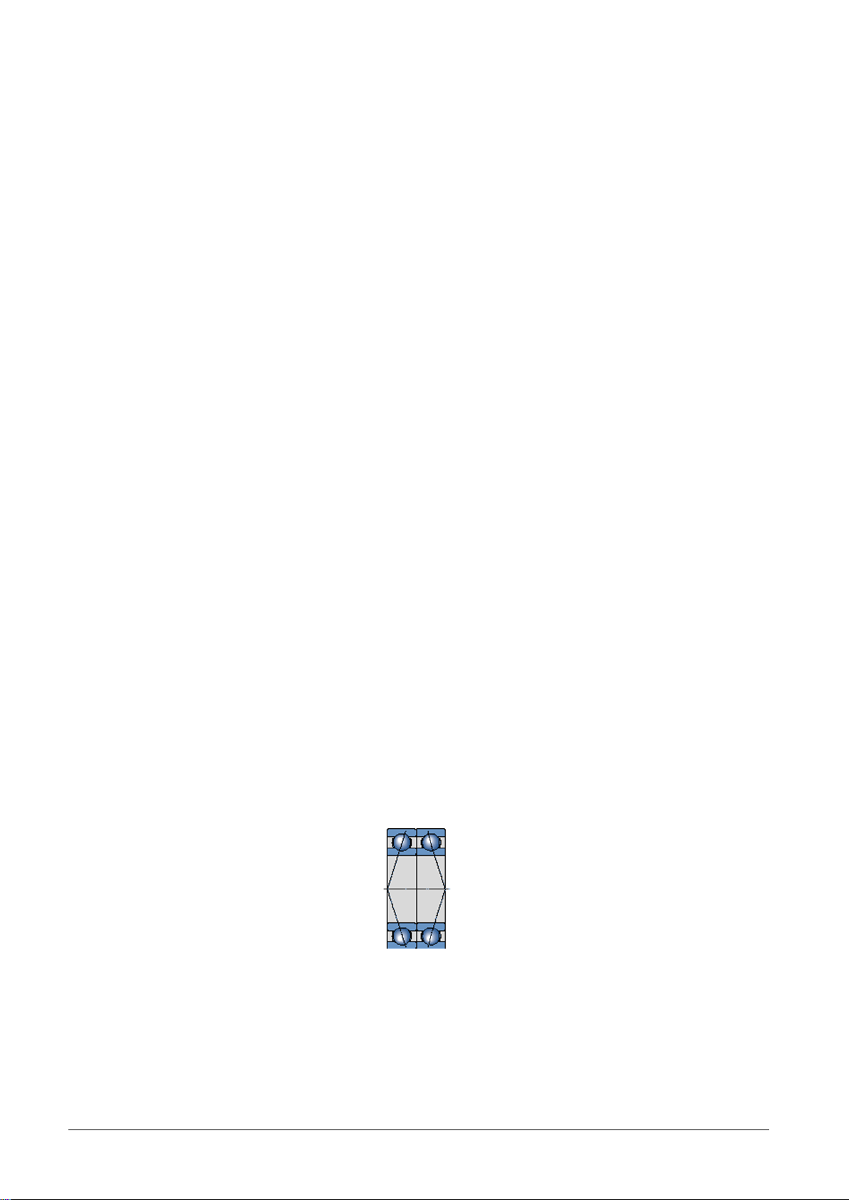
Paired angular ball bearings in O arrangement
Tighten shaft nut (50) while the bearing is still hot.
Mount bearing bracket (10).
Screw bearing cover (12) to bearing bracket (10) with nuts (M5).
Position the flinger (73) (groove in the spacer sleeve) (72).
Clamp casing cover (18U) with bearing bracket (10).
Lay horizontally discharge casing (4) with balancing bush (53) so that the shaft can be inserted (24)
(mounting plate with borehole or assembling trestle)
Place pre-mounted unit on the pressure casing (4) and tighten nuts (M2) (see Supplementary Sheet for
torque)
10 / 16