manuals.online logo
Brands
  1. Home
  2. •
  3. Brands
  4. •
  5. Xylem
  6. •
  7. Water Pump
  8. •
  9. Xylem JABSCO 18660 Series User manual

Xylem JABSCO 18660 Series User manual

OPERATION
Flexible impeller pumps must
NOT
be run dry, as the
pumped liquid is the lubricant for the impeller. Observe
the outlet and shut off pump as soon as liquid stops
flowing. An automatic level switch is convenient to
control the pump.
The pump cannot run against a closed outlet such as
encountered when using a garden hose type shut-off
nozzle.
Pressure for normal operation should not exceed 20 feet
of head (8.7 psi).
Temperature of pumped liquid may be in the range of
45° - 180°F (7° - 82°C).
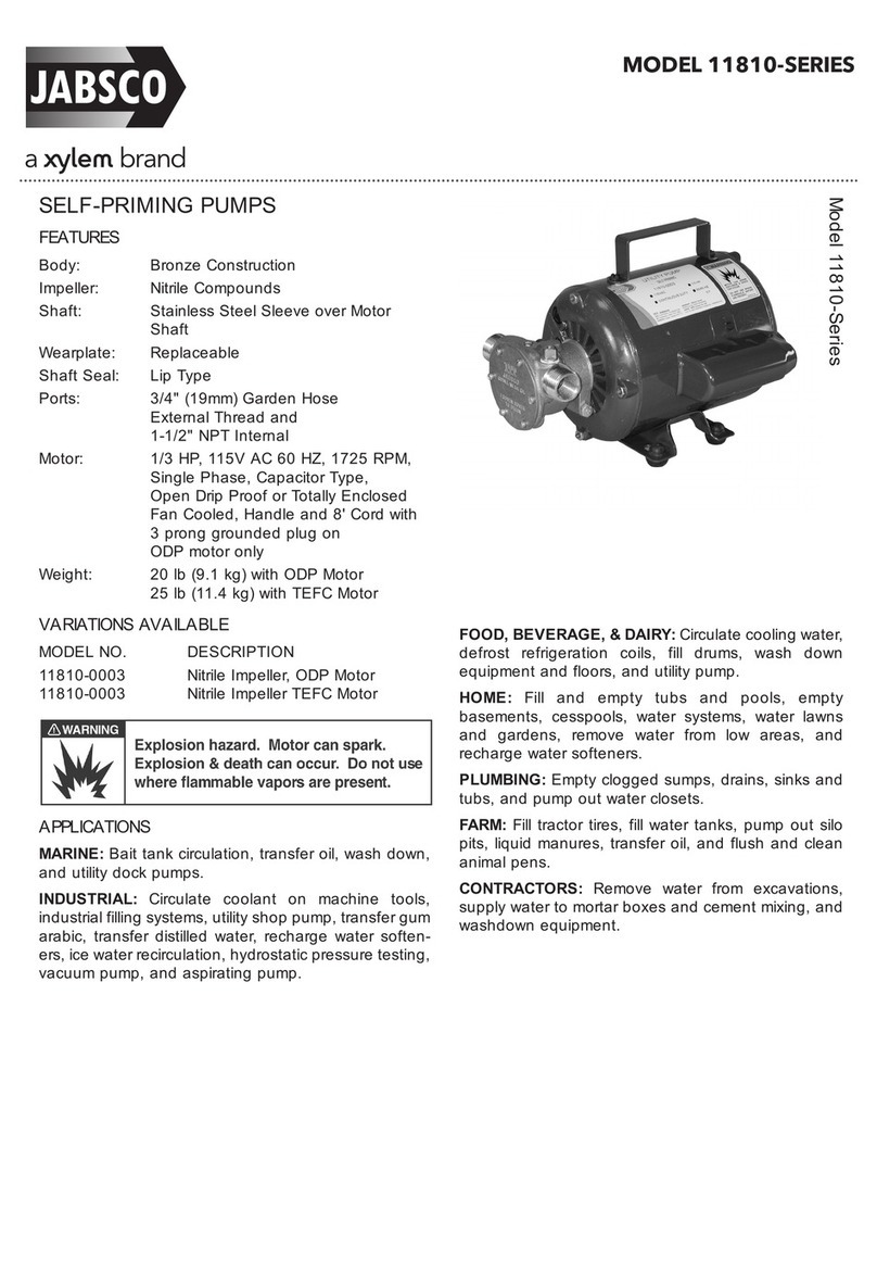
SELF-PRIMING PUMP
FEATURES
Motor: Permanent magnet type, fully
enclosed, stainless steel shaft.
Dimensions: 3" (76mm) high, 6-3/8" (162mm)
long, 4-3/4" (120mm) wide
Weight: 4-1/2 lb (2 kg) (approx.)
Body: Bronze
Impeller: Jabsco Neoprene compound
Seal: Lip type
Ports: 1/2" Internal Pipe Threads
1" External Hose Barb
Adapter for 3/4" External Garden
Hose Thread included
Motor meets USCG Electrical Standards 183.410 and
ISO 8846 MARINE for IGNITION PROTECTION on
gasoline powered vessels.
APPLICATION
Use for bilge pumping, livewell circulation, washdown
and general pumping requirements. If bilge water
contains significant amount of oil, the standard impeller
should be replaced with impeller No. 6303-0003, which is
an oil-resistant nitrile material.
Pump has a dry prime suction lift of about 4 feet (1.2m)
and a lift to 20 feet (6m) when primed. BE SURE
SUCTION LINES ARE AIRTIGHT.
WARNING
!
Explosion hazard. Do not pump 
gasoline, solvents, thinners or other 
flammable liquids. To do so can cause
an explosion resulting in injury or death.
Light housing gets hot during
operation. Do not touch during
or immediately after operation.
Burns can result.
WARNING
!
Motor runs hot—about 180° is a normal
temperature. Prolonged contact during
operation may cause a burn.
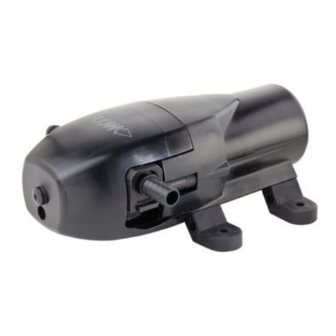
Model 18660-0121
Model 18660-0121
INSTALLATION
The pump must be mounted in a dry location – the motor
is not waterproof and must not be submerged.
SELECTION OF A COOL, VENTILATED location will
generally extend pump motor life. The unit can be
mounted in any desired position. It is best to mount so
that water dripping from a loose port connection will not
wet the motor. The pump head may be rotated 180° on
the motor to change direction of flow.
PLUMBING CONNECTIONS
Pump ports have external 1" hose barb and internal 1/2"
pipe threads. Also provided are two male port adapters
to allow the attachment of 3/4" female garden hose
fittings. Use hose that does not kink when bent and with
sufficient wall thickness to prevent collapse when used
on suction side of pump. Hoses should be routed so that
some water will be retained in pump body to wet the
impeller. Wetting the impeller aids in priming and extends
impeller life. Use a strainer on the intake hose to stop
trash and solids from going through the pump. All hoses
must have air tight connections to enable faster priming.
ELECTRICAL CONNECTIONS
Connect black wire to negative (-) terminal of battery.
The orange wire should run to a fused overload protected
switch or circuit breaker with a 15 amp rating, with a wire
from switch or breaker to positive (+) terminal of battery.
Electrical circuit must be independent of all other
accessories. Failure to connect black wire to negative
and orange wire to positive will result in backwards
motor rotation and possible motor and pump damage.
Correct motor rotation is clockwise looking at shaft end
of motor. Use proper wire size as determined by wire
table below. Should the fuse blow, replace with the same
size fuse after determining reason for blown fuse.
HEAD-FLOW CHART
Total Head Capacity
P.S.I. Feet Metres GPM LPM
2.1 5 1.5 6.3 23.8
4.3 10 3.0 5.4 20.4
6.5 15 4.6 4.2 15.9
8.7 20 6.1 2.8 10.6
Table shows approximate Head-Flow for new pump.
Overload
Protected
Distribution
Panel
Orange +
Black –
Battery
Discharge Inlet
–
+
WIRING DIAGRAM
Explosion hazard. If pump is operated in an 
area containing flammable vapors, wire leads
must be joined by insulated mechanical 
locking connectors. Loose or inadequate wire
connections can spark resulting in an explosion.
Property damage, injury or death can occur.
WARNING
!
ELECTRICAL SPECIFICATIONS – MINIMUM WIRE SIZE
AMP FUSE WIRE SIZE PER FEET OF RUN*
Model No. VOLTAGE DRAW SIZE 0'-10' 10'-20' 20'-30' 30'-40'
18660-0121 12 Vdc 8 15 #16 (1.5) #16 (1.5) #14 (2.5) #14 (2.5)
* Length of run is combined length of positive and negative conductors from power source to pump and back to ground. Wire size is SAE gauge
and metric (millimetres2).
Qty. Part
Key Description Req. Number
1 Screw Kit (4/kit) 1 91004-0090
2 End Cover 1 18647-0000
3 O-Ring* 1 18753-0660
4 Impeller* 1 6303-0001
5 Seal* 1 18753-0384
6 Body†1 18645-0000
7 Slinger 1 6342-0000
8 Motor 12V** 1 98012-0020
9 Screw (Pump to motor) 1 98019-0020
(3/kit)
12 Port Adapter Kit (2/kit) 1 18753-0103
Service Kit 90061-0006
† When replacing a pump body that uses a round end cover (3 hole
pattern) it is necessary to replace the end cover, screws and replace
the gasket with an O-Ring (order keys # 1, 2 & 3).
** For 24V and 32V replacement motors, consult the factory.
6303-0003 Oil resistant “Nitrile” Impeller available separately.
MAINTENANCE
Check wires and connections to be sure corrosion is
not adding additional resistance to the motor circuit
and causing a low voltage condition at the motor. Low
voltage can inhibit motor from starting and cause
fuse to blow. Full voltage should be available to prevent
motor damage.
NOTICE: If pump is idle for extended periods, the impeller
may stick to the pump body, preventing motor rotation
and causing blown fuses. To correct, remove end cover
and impeller, clean body and impeller, then lubricate with
water or small amounts of grease before assembly.
If pump is to be in freezing temperatures, drain by
loosening end cover screws.
A Service Kit, or at least spare impellers, should be
carried aboard to be assured of pumping capability.
DISASSEMBLY
1. Remove end cover screws, end cover and O-ring.
2. Withdraw impeller.
3. Loosen and remove two slotted hex screws, which
attach body to motor.
4. Tap body lightly between ports and remove body
from motor.
5. With a 1/2" diameter dowel, push against the shaft
seal from back (motor) side of the body to dislodge
it from the seal bore.
NOTE: Do not tamper with or disassemble motor.
ASSEMBLY
1. Lubricate seal with water and position it in seal bore
with lip, or hollowed-out side of seal, pointing
towards the impeller bore. With a 1/2" diameter
dowel, push against the shaft seal into its bore until
it contacts the bottom.
2. Lubricate motor shaft and install body on motor.
3. Lubricate impeller bore and, aligning flat in impeller
with flat on motor shaft, install impeller with clock-
wise rotary motion.
4. Install O-ring, end cover and screws.
EXPLODED VIEW
DIMENSIONAL DRAWING
Inches (Millimetres)
© Copyright 2009, ITT Corp All Rights Reserved Form: 43000-0737 Rev. 08/2009
For more information
visit us online at www.jabsco.com
12/07
AL¼ - 200 Self Priming Flexible Impeller Pump
Performance
Parts List
Dimensions in mm (inches)
AL¼ - 200 Series
Note : Performance shown is for a new pump, pumping water at
20ºC, performance may vary by up to 15%. Consult
factory for performance of alternative impeller compounds.
Key Description Part Number
A
Impeller Kit
(Contains Impeller (X),
O-Ring (X))
B
End Cover Kit
(Contains End Cover (X),
Screws (X), O-Ring (X))
C
Shaft Kit
(Contains Shaft (X),
Bearings (X), Retaining
Rings (X & X), Dust Shield
(X))
D
Service Kit
(Contains Impeller (X),
O-Ring (X), Mechanical
Seal (X), End Cover
Screws (X))
E
Seal Kit
(Contains Mechanical Seal
(X), O-Ring (X), Support
Washer (X))
Warranty: All products of the company are sold and all services of the company are offered subject to the company’s warranty and terms and conditions of sale, copies of which will be furnished upon request.
The information provided herein is for guidance only, it does not constitute a guarantee of the performance or specification of any individual product or component.
©Copyright 2003 ITT Industries 43000-0789
UK
Xylem
Bingley Road, Hoddesdon
Hertfordshire EN11 0BU
Tel: +44 (0)1992 450145
Fax: +44 (0)1992 467132
USA
Xylem
100 Cummings Center Drive
Suite 535-N, Beverly, MA 01915
Tel: +1 978 281-0440
Fax: +1 978 283-2619
ITALY
Xylem
Via Tommaseo, 6
20059 Vimercate, Milano
Tel: +39 039 685 2323
Fax: +39 039 666 307
GERMANY
Xylem
Oststrasse 28
22844 Norderstedt
Tel: +49-40-53 53 73-0
Fax: +49-40-53 53 73-11
JAPAN
Xylem
3-21-10, Shin-Yokohama
Kohoku-Ku, Yokohama, 222-0033
Tel: +81-045-475-8906
Fax: +81-045-477-1162
www.xyleminc.com
Warranty: All products of the company are sold, and all services of the company are offered subject to the company’s warranty and terms of sale, copies of which will
be furnished upon request. Details correct at time of printing. We reserve the right to change specifications without prior notice.
© Copyright 2015XylemInc. Jabsco is a trademark of Xylem Inc. or one of its subsidiaries. 43000-07
43000-0737 Rev. C 8/2015
COMMERCIAL WARRANTY
Warranty. For goods sold to commercial buyers, Seller warrants the goods sold to Buyer hereunder (with the exception of membranes, seals,
gaskets, elastomer materials, coatings and other "wear parts" or consumables all of which are not warranted except as otherwise provided in the
quotation or sales form) will be (i) be built in accordance with the specifications referred to in the quotation or sales form, if such specifications
are expressly made a part of this Agreement, and (ii) free from defects in material and workmanship for a period of one (1) year from the date of
installation or eighteen (18) months from the date of shipment (which date of shipment shall not be greater than thirty (30) days after receipt of
notice that the goods are ready to ship), whichever shall occur first, unless a longer period is specified in the product documentation (the ìWarran-
tyî).
Except as otherwise required by law, Seller shall, at its option and at no cost to Buyer, either repair or replace any product which fails to conform
with the Warranty provided Buyer gives written notice to Seller of any defects in material or workmanship within ten (10) days of the date when
any defects or non-conformance are first manifest. Under either repair or replacement option, Seller shall not be obligated to remove or pay for
the removal of the defective product or install or pay for the installation of the replaced or repaired product and Buyer shall be responsible for
all other costs, including, but not limited to, service costs, shipping fees and expenses. Seller shall have sole discretion as to the method or means
of repair or replacement. Buyerís failure to comply with Sellerís repair or replacement directions shall terminate Sellerís obligations under this
Warranty and render the Warranty void. Any parts repaired or replaced under the Warranty are warranted only for the balance of the warranty
period on the parts that were repaired or replaced. Seller shall have no warranty obligations to Buyer with respect to any product or parts of a
product that have been: (a) repaired by third parties other than Seller or without Sellerís written approval; (b) subject to misuse, misapplication,
neglect, alteration, accident, or physical damage; (c) used in a manner contrary to Sellerís instructions for installation, operation and mainte-
nance; (d) damaged from ordinary wear and tear, corrosion, or chemical attack; (e) damaged due to abnormal conditions, vibration, failure to
properly prime, or operation without flow; (f) damaged due to a defective power supply or improper electrical protection; or (g) damaged
resulting from the use of accessory equipment not sold or approved by Seller. In any case of products not manufactured by Seller, there is no
warranty from Seller; however, Seller will extend to Buyer any warranty received from Sellerís supplier of such products.
THE FOREGOING WARRANTY IS EXCLUSIVE AND IN LIEU OF ANY AND ALL OTHER EXPRESS OR IMPLIED WARRANTIES, GUARANTEES,
CONDITIONS OR TERMS OF WHATEVER NATURE RELATING TO THE GOODS PROVIDED HEREUNDER, INCLUDING WITHOUT LIMITA-
TION ANY IMPLIED WARRANTIES OF MERCHANTABILITY AND FITNESS FOR A PARTICULAR PURPOSE, WHICH ARE HEREBY EXPRESSLY
DISCLAIMED AND EXCLUDED. EXCEPT AS OTHERWISE REQUIRED BY LAW, BUYERíS EXCLUSIVE REMEDY AND SELLERíS AGGREGATE
LIABILITY FOR BREACH OF ANY OF THE FOREGOING WARRANTIES ARE LIMITED TO REPAIRING OR REPLACING THE PRODUCT AND
SHALL IN ALL CASES BE LIMITED TO THE AMOUNT PAID BY THE BUYER FOR THE DEFECTIVE PRODUCT. IN NO EVENT SHALL SELLER BE
LIABLE FOR ANY OTHER FORM OF DAMAGES, WHETHER DIRECT, INDIRECT, LIQUIDATED, INCIDENTAL, CONSEQUENTIAL, PUNITIVE,
EXEMPLARY OR SPECIAL DAMAGES, INCLUDING BUT NOT LIMITED TO LOSS OF PROFIT, LOSS OF ANTICIPATED SAVINGS OR REVENUE,
LOSS OF INCOME, LOSS OF BUSINESS, LOSS OF PRODUCTION, LOSS OF OPPORTUNITY OR LOSS OF REPUTATION.
This manual suits for next models

1

Other Xylem Water Pump manuals

Xylem Flygt 3060 User manual

Xylem

Xylem Flygt 3060 User manual

Xylem LOWARA e-SVE User manual

Xylem

Xylem LOWARA e-SVE User manual

Xylem JABSCO 2620 Series User manual

Xylem

Xylem JABSCO 2620 Series User manual

Xylem Bell & Gossett 2WC041A User manual

Xylem

Xylem Bell & Gossett 2WC041A User manual

Xylem DRAINAGE RED JACKET Series Manual

Xylem

Xylem DRAINAGE RED JACKET Series Manual

Xylem Goulds J Series User manual

Xylem

Xylem Goulds J Series User manual

Xylem AC Fire Pump 8100 Series User manual

Xylem

Xylem AC Fire Pump 8100 Series User manual

Xylem Lowara DDC Quick guide

Xylem

Xylem Lowara DDC Quick guide

Xylem Lowara Micro PRESFIX User manual

Xylem

Xylem Lowara Micro PRESFIX User manual

Xylem Flojet G55 Series User manual

Xylem

Xylem Flojet G55 Series User manual

Xylem Lowara Scuba Dry Series Manual

Xylem

Xylem Lowara Scuba Dry Series Manual

Xylem Jabsco 18620-0003 User manual

Xylem

Xylem Jabsco 18620-0003 User manual

Xylem Bell & Gossett e-82 Series User manual

Xylem

Xylem Bell & Gossett e-82 Series User manual

Xylem GOULDS 45HB Operating instructions

Xylem

Xylem GOULDS 45HB Operating instructions

Xylem LOWARA TP1 User manual

Xylem

Xylem LOWARA TP1 User manual

Xylem ecocirc XL User manual

Xylem

Xylem ecocirc XL User manual

Xylem JABSCO 11810 Series User manual

Xylem

Xylem JABSCO 11810 Series User manual

Xylem Flojet G55 Series User manual

Xylem

Xylem Flojet G55 Series User manual

Xylem FLOJET M50 User manual

Xylem

Xylem FLOJET M50 User manual

Xylem Lowara Scuba Series Original instructions

Xylem

Xylem Lowara Scuba Series Original instructions

Xylem Flowtronex SILENT STORM User manual

Xylem

Xylem Flowtronex SILENT STORM User manual

Xylem Flygt 3201 Owner's manual

Xylem

Xylem Flygt 3201 Owner's manual

Xylem Bell & Gossett e-1510 Series User manual

Xylem

Xylem Bell & Gossett e-1510 Series User manual

Xylem GOULDS NSC Owner's manual

Xylem

Xylem GOULDS NSC Owner's manual

Popular Water Pump manuals by other brands

Kohler WA 2.0 owner's manual

Kohler

Kohler WA 2.0 owner's manual

Veolia AS Series Installation, operation & maintenance instructions

Veolia

Veolia AS Series Installation, operation & maintenance instructions

Aussie Pumps QP60TDK Series Operations & parts manual

Aussie Pumps

Aussie Pumps QP60TDK Series Operations & parts manual

Decko BULLDOG 90000 owner's manual

Decko

Decko BULLDOG 90000 owner's manual

MATO pneuMATO 1 operating instructions

MATO

MATO pneuMATO 1 operating instructions

ARO ARO 666250-XXX-C Operator's manual

ARO

ARO ARO 666250-XXX-C Operator's manual

Pentair Jung Pumpen Compli 120/2 M instruction manual

Pentair Jung Pumpen

Pentair Jung Pumpen Compli 120/2 M instruction manual

RIDGID TP-4000 user manual

RIDGID

RIDGID TP-4000 user manual

Flotec AT250701 owner's manual

Flotec

Flotec AT250701 owner's manual

Marco UP66/E-DX Instructions for use

Marco

Marco UP66/E-DX Instructions for use

Black Knight HCPRO 12 CFM Operation manual

Black Knight

Black Knight HCPRO 12 CFM Operation manual

Kremlin-Rexson AIRMIX 10-25 GT Translation of the original manual

Kremlin-Rexson

Kremlin-Rexson AIRMIX 10-25 GT Translation of the original manual

Warren rupp SANDPIPER SH2-M Service & operating manual

Warren rupp

Warren rupp SANDPIPER SH2-M Service & operating manual

Pumpex P 401 Starting and operating instructions

Pumpex

Pumpex P 401 Starting and operating instructions

Dupla MARIN P4 Smart operating instructions

Dupla MARIN

Dupla MARIN P4 Smart operating instructions

Espa Tecnotec instruction manual

Espa

Espa Tecnotec instruction manual

MasterCraft 312222-01 owner's manual

MasterCraft

MasterCraft 312222-01 owner's manual

Wilo Stratos ECO 25/1-3 Installation and operating instructions

Wilo

Wilo Stratos ECO 25/1-3 Installation and operating instructions

manuals.online logo
manuals.online logoBrands
  • About & Mission
  • Contact us
  • Privacy Policy
  • Terms and Conditions

Copyright 2025 Manuals.Online. All Rights Reserved.