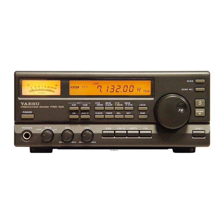
Yaesu FRG-100 User manual

Operating
Manual
YAESU
MUSEN
CO.,
LTD.

Contents
General Description
.
.
.
.
.
.
.
.....
1
Specifications 2
Accessories
&
Options 3
Front PanelControls
&
Connectors 4
Liquid CrystalDisplay
5
Rear Panel Controls
&
Connectors
6
Receiver Installation
.
.
.
.
..
.
. .
.
.
.
7
PreliminaryInspection
7
Location of the Receiver
7
Grounding
7
DC
Power Connection
7
Front Panel Angle
&
ReferenceChart
7
ShortwaveSignals
&
Propagation
8
Antenna Considerations
..
.
.
.
..
. .
.
9
Antennas for LF
&
MW
Reception
9
AntennasforShortwave 10
DipoleConstruction 10
Typical AntennaInstallations 12
Power-Up
&
Custom Settings
..
.
....
12
Operation
.
,
....
..
....
,
.
...
.I3
Getting Started Tutorial 13
FrequencyTuning 13
ProgrammableTuningSteps 14
Fast Tuning Key 14
SignalReception
.
,
.
.
.
,,
...
.
,
.
.I5
AM
Broadcast Reception 15
Broadcast Band SelectionMode 15
SSB Reception 15
Ajusting SSB Carrier FrequencyOffset 16
CW (Radiotelegraphy)Reception
16
Adjusting BFO Beat Note 17
Selectable
CW
Sideband 17
Reverse BFO Offset 18
FM
Reception 18
ReceiverSquelchSetting 19
Fading
&
NoiseRejection 19
Noise Blanker Setting 19
RF Attenuation 19
Beep Settings 19
ChangingReceiver Selectivity 20
PLL
Offset 20
Memory Operation
.
..
.
.
.
.
. .
.
. .
.
21
Introduction 21
Memory Storage 21
CheckingMemory Contents 21
Checking
&
Programming Memories
from the VFO Mode
AutoMemoryArrangement
Erasinga Memory Channel
Memory Tuning
WritingMemory Contents to VFO
Scanning Operation
. . .
...
.
Introduction
Memory Scan
Scan Stop
Memory ScanSkip
Band Scanning: MemoriesLo
&
Hi
PriorityScan
SelectableGroupScan
CommonGroup Channel
Scan
CommonLetter GroupScan
Using SelectableGroup Scanning
Broadcast Band Scanning
Clock
&
Timer Operation
.
.
.
,
,
Format
&
DefaultDisplay
DefaultDisplay
LCD Backlighting
Hourly limeAnnunciator
Timer
&
SleepFunctions
TimerCyclingand Operation
DiagnosticTest
Installing Internal Accessories
.
.
Top CoverRemoval
FM
UNIT-100Installation
Beep VolumeAdjustment
OptionalCW Crystal Filters
Fuse Replacement
Bottom CoverRemoval
TCXO-4 Installation
Lithium Battery
BackupSwitch
Cover Screws
CAT Control System
.
,
.
.
. .
.
.
Data Returned From FRG-100
FRG-100CAT Commands
StatusUpdate Data Organization
StatusUpdate Data Selections
Read FlagsData
StatusUpdate Data Selection

Description
The FRG-100 is a high-performance communi-
cations receiver providing general coverage recep-
tion in CW, SSB, AM and
FM
modes from 50 kHz
to30 MHz. The latest microprocessor technology is
used to merge performance and reliability with
easyoperationandfunctionalsimplicity.TheFRG-
100incorporates features that both casual and seri-
ous shortwavelisteners will appreciate.
Reception modes and most receiver functions
are push-button selectablefrom the front panel.
A
crisp back-lit LCD with adjustablebrightness pro-
vides frequency read-out and important opera-
tional status at a single glance. Selectable tuning
stepsof 10Hz, 100Hz, or 1kHz are standard, with
other tuning steps user-programmable. Fifty
tun-
able memories storefrequencyandmodeinforma-
A special Broadcast Band mode enables con-
venient selection of
16
pre-programmed interna-
tional broadcast bands
(LW
-
11 Meters). The
FRG-100's adjustable
SSB
Carrier Offset permits
you to custom tailor thereceiver's audioresponse.
CW enthusiasts will enjoy the ReverseBFO Offset
and Selectable CW Sideband. Installation of the
optional 250 or 500 Hz narrow filter further en-
hances CW reception and interference rejection.
Other features include a noise blanker, all-mode
squelch, andrelative signal-strengthmeter,
TheYaesu CAT system provides a direct link to
the CPU
in
the FRG-100, allowing a personal com-
puter with theYaesu FIF CAT Interface Unit to add
other functions as desired, such as automatic tun-
ing, customized scanning systems and of course
remote control of most receiver functions.
tion, two additional memories provideband-edge
information used for scanning. Beforeconnecting the power cord, you should
read the
Receiver
Instnlllrtion
sectioncarefully,heed-
Two programmable 12/24-h0ur and ing thewarnings in that sectionto avoiddamageto
On/Off/Slee~-timersenables You to automat- the set. After installation, please take time to work
ically switch thereceiver on/off to record or listen through the
Operation
chapter. This manual is in-
to
your favorite broadcasts. Multi-function scan- tended toberead while sittingin front of the FRG-
ning enables searching for new stations or scan- 100,so you can try out each control and feature as
ning within known bands. they aredescribed.

Specifications
Frequency Range:
50
kHz
-
30Mhz Circuit Type: dual-conversion superheterodyne
Reception Modes: USB. LSB.
CW,
AM,
FM
(optional) IntermediateFrequendes:
lst
IF
47.21
MHz
Frequency Stability:
<
f
10ppm, from -10 -+50
O
C
2nd
IF
455 kHz
<
f
2
ppm, from 0
-
+50
OC
(w/TCXO option)
Squelch Sensistivity:
Standard Tuning Steps: 10/100
Hz
(CW/SSB)
100Hz/
1
kHz (AM/FM) 1.8
-
30
Mkz
(CW,SSB, AM): 2.0 yV
.
.
28
-
30
MHz
(FM): 0.32pV
Sensitivity: IF Rejection (1.8
-
30 MHz): 70 dB or better
(for10dB
S/N,
0dBp=1
pV,
FM 12dB SINAD)
Image Rejection (1.8
-
30
MHz):
60
dBorbetter
Selectivity:(-6/-60dB):
Audio Power Output:
at
least 1.5watts into4
i2
with 10
%THD
Audio OutputImpedance: 4 to 8
Q
Antenna Impedance: Lo-Z 50
Q
unbalanced
Hi-Z450
Q
unbalanced
Supply Voltage:
DC
11
-
14V, negative ground
Power Consumption(max.):1.2A
Dimensions(WHD):238
x
93
x
243
mrn
Weight: (approx):3kg (6.6lb.)
Specifications are subject to change in the interest of tech-
nical improvement, without notice or obligation.

Accessories
&
Options
SuppliedAccessories
DC
Power Cord (T9019399) 1 ea.
C!
,
RCA
Plug (P0090544)1ea.
Options
CW
Narrow FilterYF-110 CICN (5001250
Hz)
Mini Phone Plug
(P0090034) 1ea.
fl
I,
Sub-Mini Phone Plug
(P0090970)1ea.
Fuse (Q0000021)2 ea.

Front Panel Controls
&
Connectors
1
POWER
This button turns the receiver
on/off, however, the clock and memory backup
functions stay on and are not affected. To avoid
switching spikes, make sure it is OFF when you
applya
DC
power sourceto the rear paneljack.
2 VOL
This adjuststhe volume of the receiver
loudspeaker or headphones. It should be set for a
comfortable level onlywhen the
SQL
control isset
fully ccw, so that a signal or noise can
be
heard.
Adjusting thiscontrol
does
not
affecttheaudiolevel
at the
REC
jack (describedlater).
3
SQL
The squelch control sets the signal level
at which the receiver audioismuted in all modes.
This control is normally kept fully ccw, except
when scanning, and during FM reception. Scan-
ning stops when the squelch is open. See page 19
again will toggle between USB and LSB mode,
pressing the
CWIN
and
AMIN
keys a second time
will select the narrow
IF
filter (if installed).
7
FAST
This key enables faster tuning rates
using the main
VFO
knob by increasing the tun-
ing increment (step) size. Increment steps are de-
termined by mode selection and you. Standard
tuningincrementsare100Hz
&
1kHz for AM/FM
and 10 Hz
&
100Hz for SSB/CW Custom tuning
steps can be programmed for special applications,
see page 14.
8
UP
A
DOWN
V
Pressing either key momen-
tarily will step the receive frequency up or down
100 kHz or 1 MHz (selected by the
FAST
key).
Continueholding eitherkey forrepeated stepping.
for squelch setting.
9
This knob tunes the operating frequency of
This
1/4"jack
a
the
VFO
ora recalled memory. Tuningrateisdeter-
with either a
2
or 3-contact plug. When a plug is mined by the frequency step selected.
installed, the loudspeaker isdisabled.
10
ATT 6dB, 12dB,
These switches provide
6
MEM
DWN
This
rotary or 12dB of
RF
attenuation to protect the receiver
through the
52
memory channels. front-endfrom strongsignaloverload.
A
total of 18
6 SSB CW/N AM/N FM
These keys select the dB of attenuation can be obtained by selecting
various reception modes. Pressing the
SSB
key both.

11
NB
Thenoise blanker helps to reduce inter-
ferenceexperienced fromman-madeimpulse-type
noise. Normally,
if
noise is not present, this switch
should be kept in the un-depressed position.
12
AGC-F
Pressing this key selects thereceiver
Automatic Gain Control, which reduces fading of
received signals. The
fnst
recovery setting (de-
pressed) is preferred for
SSB
&
CW reception.
13
The following keys control various memory
and VFO operations and are described in detail in
the
Operution
chapter of this manual:
VFOIMEM
This key selects VFO or memory
channel tuning and operation.
MEM CLEAR
Pressing this key for longer than
1
/2
secondwill erasethe currently stored informa-
tion in memory. Repressing the key will re-enter
the information if new data has not been stored.
VFO MEM
To store the currently displayed
frequency and data into memory, press
and
t~oltll
this key for longer than 1/2 sec.
MEMbVFO
Shifts the contents of the selected
memory channel into
VFO
without erasing the
stored memory data.
CLOCK
Used to select and enter the correct
time on both clocks.
TIMER
Used for selecting and programming
Timer operation.
SEL
and
SET
These keys are used with the
Timer and Clock functions.
14
LOCK
This button disables the main VFO
tuning knob, other controls and functions are not
affected.
15
DIM
This key selects bright or dim back-lit
LCD
illumination. Pressing this key while the ra-
dio is turned off will illuminate the display for
approximately
5
seconds.
16
SCAN
Pressing this button starts scanning
operation, pressing it again stops the scanning.
17
SCANSEL
Repeatedly pressing this button
selects thereceiver scanning modes (memoryscan,
priority scan, or group scan).These are covered in
greater detail in the
Opwntion
chapter.
Liquid Crystal Display
Reception Freq./Time
Readout Narrow IF Fil-
inOperation
Fast Tuning Step
enabled
Lock enabled

Rear Panel Controls
&
Connectors
000
0
DClZV
IN
EXTSPKR
REC
REMOTE MUTE
1
DC
12
V
IN
This is the 13.8-volt
DC
power
connector. Be suretousea coaxial-typebarrel plug.
A
regulated power supply capable of providing at
least 2 amps is recommended. Be sure to observe
proper polarity and ensure that the center conduc-
tor iswired
+
(positive)and the outer conductor is
-
(GND).
2
CAT
This 6-pin
DIN
plug allows external
computer control of the FRG-100 when used with
the optional FIF Interface and software. See the
CAT Control System
chapter for details.
3
EXT SPKR
This 2-contact mini phone jack
provides receiver audio for an external loud-
speaker with an impedance of 4
-
16Q. Inserting a
plug in thisjack disables the loudspeaker.
4
REC
Thisjack provides a constant level (100
mV
@
IkQ)audiooutput,which is
umfected
bythe
VOL
control. This audio can beused for recording
purposes, and for connection to data demodula-
tor/decoder equipment.
5
REMOTE
Use thisjack to remote control an
external tape recorder. When receiver squelch
opens, this jack goes to ground, closing the circuit
to activate a tape recorder or otherdevice.
6
MUTE
If
using the FRG-100 with a trans-
ceiver, shorting thisjack during transmit will mute
receiver output and attenuate RF signal input.
Check with information provided with your par-
ticular transceiver for proper connection.
I
7
ANT
LO-Z
Connect the 50
Q
coaxial feed line
to your low-impedance antenna here using a type-
M
(PL-259)
connector. See the
Antenna Considera-
tions
chapter for antenna types and installation.
8
BACK
UP
ONIOFF
This switchesthelithium
memoryback-upbattery. It normally shouldbeleft
in the
ON
position.
9 ANT
HI-Z
Use these spring-loaded terminal
connectors to connect a high-impedance antenna.
10
GND
Connect thisterminal toa quality earth
ground. See the
Xeceivw
Installation
chapter for de-
tails on grounding.

Receiver
Installation
Preliminary Inspection
suppresspossible- computer-noise receivedby the
radio. Ask your Yaesu dealer, or consult a radio
Inspect the receiver immediately handbook if you need information on thebest way
upon opening
the
packing Confirm
that
of obtaining a good connection to ground at your
the controls and switcheswork freely, and inspect location.
the cabinet for damage.
If
any damage is found,
contact the shipping company (or dealer, if you
purchasedit over the counter)right away.Savethe
packingmaterialsin caseyou need to return the set
for service.
If you purchased optional internal accessories,
installthem asdescribed in
InstallinpInterrrnl Acces-
sories
chapterafter first carefullyreading this man-
ual.
Whilereadingthis chapter,refer tothephotosof
the panels for the locations and functions of the
DC Power Connection
controls andjacks. ADC power cableis supplied with the receiver.
Danger!
Never
use natural
(LP)
gas lines
w
electrial con-
duit piping as anearthground connection,
dueto
the risk of explosion or electrical shock.
If
you are unsure about the use of piping in
your dwelling, first check with your local
utilities before making anyconnections.
Location of theReceiver
To assure longlife of components, make sureto
provide adequate ventilation around the cabinet.
Do not place the receiver on top of other heat
generating devices, or place objects such asbooks
or papers on top of the receiver. Place the the re-
ceiver on a hard flat surface. Avoid heating vents
and window locations that could expose the re-
ceiverto excessivedirect sunlight, especiallyin hot
climates. Before plugging in the receiver the first
time,make sureyour supplyvoltageiscorrect,and
that your ground and antenna are connected as
described next.
Grounding
At one end isa pre-assembled coaxial-typebarrel
plug for connection at the rear panel of the radio,
the other end is to be connected to an appropriate
DC power source (if the optional PA-11 B/C AC
adapter is used, this cable is not needed, and
shouldbe kept for possible futureuse).Before wir-
ing to any
DC
power source, first ensure proper
voltageand polarity.
Please notethecautionbelow.
To
avoid damage from voltage transients, ensure that
the receiver
POWER
switch is OFFwhenever con-
necting or disconnecting DC power.
Front Panel Angle
b
Reference Card
If your installation places the FRG-100 much
below eyelevel you may want to propupthefront
For protection fromshock and proper perform- of the radio for more comfortableviewing. Awire
ante,
connect the
GND
terminal on the receiver bail on the bottom of the FRG-100 can be folded
rear panel to a good earth ground, using
a
down for this purpose. A handy laminated world
braided cable
of
the
length possible.
A
time and receiver functions card is also accessible
good
earth
ground
can
be
obtained
connection
beneath thebottom cover,Simply slide it out
from
to a conductive rod driven several feet into the from the dual slotted rails.
earth, or alternatelyby connection to a nearby cold
-
-
water pipe (checkin newer dwellingsin case plas-
tic PVC pipe is installed in-line since this would
insulate the connection from earth-ground). All
other station equipment should be connected to
the same ground cable, as close together as possi-
ble. If you use a computer with or near the FRG-
100, you may need to experiment with grounding
and location of both the receiver and computer to
Warning!
Pernmnent damge myresult if inzproper st~pply
voltage
is
applied to the receiver. Your zuarranty
does not cover damnge mused by applimtion of
AC,
reversed
DC,
or
DC
outside of the specified
range of
12-14
VDC.

Shortwave Signals and Propagation
Shortwave signals are transmitted by stations
running high power output and use elaborate an-
tenna systems. Good reception dependsona prop-
erty of the ionosphere (a layer of the atmosphere)
which causes the reflection of signals back to the
earth.
Depending on several factors, including the
time of day, the season, and current solar activity
(determinedprimarily by sunspots), the optimum
frequency for reflection over a particular distance
will change. Thus, in order to hear distant stations
over a long period of time on a particular day, you
willlikelyhavetochangeyour receivingfrequency
(consistent with thebroadcast schedules) in order
to adjust for changing propagation conditions.
Daytime propagation conditions are generally
best on frequencies from about 12-14 MHz and
higher. Propagation atnight will be generally best
on the2-15MHz bands. Thereareexceptions,how-
ever; during periods of high solar activity, the
21
MHz band may, for example,be excellent for long
distancepropagation wellinto the night. However,
it would be highly unusual for the bands below
about
8
MHz to support transoceanic propagation
throughout the daytime period.
Surface
Wave
Earth
Signal Propagation
When reading broadcast station schedules,con-
sider not only your local time, but also the local
time at the transmitter location. Let us use the
example of two broadcast stations, one in Tokyo,
and one in Moscow, both operating on 6 MHz at
6:00
P.M.
local time (forour example, letussaythat
you live in New York, U.S.A.). Because there are
night-time conditions covering most of the North
Atlanticpath that a signalwould follow fromMos-
cow to New York, you would normally have a
good chance of receiving thebroadcast from Mos-
cow. However, thepath fromTokyoto New York is
largely a daylight path, and asdiscussed earlier, it
would bedifficult, if not impossible, tohear Tokyo
at the same time and frequency.
However, the Tokyo schedule may include a
broadcast schedule on 15MHz at the same time.
The 15MHz region (k5MHz) is a middle ground
which often supports around-the-clock propaga-
tion. You would have a better chance of hearing
Tokyo on 15MHz at this time because the path is
largely overdaylight.
Broadcast stations are aware of this phenome-
non, and this is why their schedules indicate
"North American Service" or "Programming
Beamed at Southeast Asia". They take propagation
conditionsintoconsideration,and aim their anten-
nas carefully, to try to reach their target at a time
when people will be at home to listen.
The season is also very important for several
reasons. For example, at 4:00 P.M. in New York in
June,the sunis stillhigh
in
the sky. But at4:00 P.M.
in December, twilight is fast approaching and
night-time conditions are taking over the North
Atlantic path. Broadcast stations adjust their
schedules to use the lower frequencies (below 10
MHz) more heavily in the winter, because of the
increased signal distancecovered.
Signalsdonot often follow the shortest distance
between two points (called the "Great Circle
Path"). They sometimes follow a bent path, or go
exactly oppositeof thegreat circle.This iswhyit is
sometimespossible to hear Tokyo from New York
on
7
MHz late in the afternoon in the winter, even
though the great circle path is in daylight; the sig-
nals travel along a darkness path around the
world. The fact that many stations arelouder, and
that the transmitting antenna may not be beamed
on theoptimumpath atthat time,makes reception
extremely difficult. But this is the excitement of
shortwavelistening
-
hearing theunexpected.
In conclusion, use higher frequencies (15 MHz
and above)as your main daylight bands, and fre-
quencies below 15 MHz for prime night-time re-
ception. Look for a peak in 26 MHz propagation
towards the east an hour or so after sunrise, and
toward the west around sunset. Careful planning
ofyour operatingtimes, frequencies, andtheuseof
broadcast schedules will provide endless hours of
listening enjoyment from around the world.

Antenna Considerations
The FRG-100 was designed to operate with an
antenna connected to the rear panel connectors.
Thisallows you to take fulladvantage of thebetter
reception possible usingoutdoorantenna systems,
which would not be possible with an internal
"loopstick" or telescoping whip antenna, such as
used on portable radios. However, if portability is
required or if there is no space for an external
antenna, the FRG-100 can beused with an indoor
or "active" antenna. In most cases, however, a
proper outdoorantenna cut ortuned for thereceiv-
ing frequency range will usually provide better
performance.
The type and installation of the antenna are
critical to the proper performance of your receiver.
While somestrong signalscanbereceived withjust
about any piece of wire connected to the proper
terminal, longdistance
(DX)
orlow power stations
will require additional effort and care in choosing,
constructing and installing the antenna.
If
you are
new to antenna theory and construction, please
refer to a a shortwaveantennahandbookfor expla-
nations and ideas. A few basic antennas are de-
scribed next to help get you started.
Antennas for Low and Medium Frequency
Reception
(50
-
1600
kHz)
Fair all-around reception is possible using a sin-
gle random-length wire as long as possible con-
nected to thewhite
HI-Z
spring-loaded terminal on
the rear panel. The wire should be supported as
high above ground as possible using insulators at
the ends, and should be located as far as possible
from any other objects. Insulated wire is generally
preferable, mainly because of it's corrosion resis-
tance. In general, thelonger thewire, the better the
performance in these bands. A good earth ground
connection, as described in the
Receiver
I~istallntioti
chapter, is essential to good performance with a
random wire antenna.
GND
HI-Z
ANT
LO-z
m:m
I
Rear-Panel Antenna Connections
If there are strong broadcast stations located
nearby, a random wire antenna can receive so
much energy from those stations that the receiver
may overload, particularly if the antenna is very
long. This can result in distorted signals appearing
on the wrong frequencies (wherethe station isnot
transmitting). The
ATT
control on the FRG-100 is
provided to reduce the overall sensitivity of the
receiver and thus reduce the susceptibility to such
overloading, but also reduces the strength of the
desired signals. In situations where this is unac-
ceptable, we recommend using an antenna tuner
connected between the receiver and antenna, al-
lowing precise impedance matching at the receiv-
ing frequency, while suppressing signals at other
frequencies. An antenna tuner allows a random
wire antenna to provide good performance at LW
and MW frequencies.
/-
Long-Wire Antenna Construction
Antennas for Shortwave
(2
-
30
MHz)
Optimumperformance on frequenciesbetween
2
and
30
MHz can be obtained using a tuned or
self-resonantantenna with animpedance of
50
R
at
the receiving frequency. However, such antennas
generally perform best within a certain band, giv-
ing reduced performance outside this range. For
correct operationanyantenna shouldbe connected
to the receiver by either as coaxial cable (to the
LO-Z
50-Q coaxial jack), or a high-impedance
"open wire" feed line to the spring-loaded
HI-Z
and adjacent black terminals, depending on the
feed point impedance of the antenna (whichmust
be matched by the feedline and receiver connec-
tions).

Performance on a specificband can be achieved
usinga simpleresonant dipoleantenna, consisting
of two equal-length wires cut for the center of the
desired band. The dipole can be constn~ctedfrom
availablematerials, or from a kit availablethrough
your dealer.
If
you wish tomake such a a dipolefor
optimum performance at a certain frequency, the
following formulas can be used to obtain the cor-
rect overall length (add a little extra to allow for
attaching at the ends).
Length (meters)
=
142.5/frequency (MHz),or
Important!
For proper reception, ensure that the
LO-Z
-
HI-Z
antenna selector switch on therear panel
of the receiver isin the correct position for the
antenna being used. To switch antennas, en-
surethereceiver isturned off and thepower is
disconnected, then gently slide the switch
leverusing the tip of a pointed object (such as
a ball-point pen).
Length (feet)
=
468/frequency (MHz) The above HFantennascan be used with vary-
ing success on frequencies outside of their opti-
mum range,
in
which case an antenna tuner as
mentioned earlier can provide considerable im-
provement
in
performance. Also, good low fre-
quency reception can sometimesbe achieved with
an HF antenna if the two feedline conductors are
connected together to the white
HI-Z
terminal on
the receiver, but this can also introduce overload-
ing or objectionable noise.
"Length"
The two legs of the dipole must be insulated
from their supports at each end, and from one
another in the center. Reception of long distance
(DX)
stations requires that horizontal antennas be
as
high above grorlnd
m
possible
(with a height of a
little over twice the length of the antenna calcu-
lated above considered about optimum). Connec-
tion should be made using 50 or
75
Ohm coaxial
cable, with the center conductor connected to one
endand theshield to the other.The other end of the
cable connects to the
LO-Z
coaxialjack on the rear
panel of the receiver.
If
the antenna is installed
vertically, it need not be so high (the optimum
center feed point is about the sameas the length of
the above formulas),but in this (vertical) case the
earth ground is more critical.
U
Danger!
Do not install any antenna
nem
electric power
lines,
zu?lere
tlzere could be any chance of tlze an-
tenrrn corning into contact with livewires.
HI-Z
ANT
LO-Z
-
101
I
I
Rear Panel Antenna Selection
Dipole Construction
Insulator
OUPLING
RING
SOLDER
HOLE
Installing
PL-259
Connector
Insulator
COAX
Cable
page
10
.
.v

I
I
GND
HI-Z
-
I
101
I
I
Typical
LF-MW
Antenna Installation
GND
HI-Z
Typical
HF
Antenna Installation

Power-Up Customization
&
Button Combination Settings
By pressing and holding certain buttons while turning on the FRG-100, you can change many default
settings, and customize features to your own preference. Other important settings can be selected by
pressing and holding the
SET
button with other key combinations,as described in thebottom table.
note
:'
indicateadvancedfunctions for experiencedoperators, we do notrecommendchangingthese defaultsettings until their
operationand effect are understood. Seetext for
a
descriptionof each function.

Operation
Getting Started Tutoria
I
Basic operation of the FRG-100 is simple, how-
ever, some of the more advanced features can be
confusingat first if you are not familiarwith their
function. Please read this section carefully while
trying out each step on the receiver. Refer to the
photos and panel diagrams for the locations and
basic functions of the controlsand jacks.
Beforeplugging in thereceiver forthefirst time,
ensure that your power supply voltage is correct,
and that your ground and antenna are connected
as described in the
Receiver Installation
chapter.
Then preset thefollowingcontrols:
POWER:
Off
VOL:
10 o'clock
SQL:
counter-clockwise(ccw)
Connect your
DC
power source at the receiver
rear panel. The flashing clock time should be vis-
ibleon the front panel display,thisisnormal.Now
press the
POWER
switch on. The meter and dis-
play should light up.
If
the display is toobright or
too dim, press the
DIM
key to select the brightness
you prefer. Adjust the
VOL
control for a comfort-
able audio level at the speaker or head- phones (if
they areused).
If
nothing happened, re-check your
power connections.
Take amoment to study the displayYou should
see
"VFO"
or
"MEM"
at the left, the receive fre-
quency digits, mode selection directly above, and
the
"BUSY"
indicator to the left showing that the
squelch is open. Rotate the
SQL
control clockwise
(CW)to checkthat the indicationdisappearswhen
the squelch closes, and then return it fully ccw. At
the right of the frequency read-out you will see a
smaller two-digit memory channelnumber.
For now, we want to begin in VFO operation.
You may find it easier to switch betweenVFO and
Memory operation by simply pressing the
VFOIMEM
button. This method allows you to
leave any settings in the VFO.
If
"VFO"
does not
appear totheleft of thefrequencydisplay,pressthe
VFOIMEM
again to select it.
Frequency Tuning
The FRG-100 provides a combination of the
main tuning knob, up/down keys, and selectable
tuning speedstoallow fastand accuratefrequency
selection.After first selectingthedesired receiving
mode at the bottom of the panel, press the
UP
A
DOWN
V
buttons (totheright of the tuning knob)
to stepto a frequencyband for reception. Pressing
eachkey
mom~tmily
will stepthefrequencyin the
direction chosen, and is accompanied by an audi-
blebeep fromtheloudspeaker. Pressing
and holding
either key results in repeated frequency stepping
until released. The main tuning knob can then be
used for tuning around the immediate vicinity or
band just selected.Pressing the
FAST
key will in-
creasethe step size and tuning rate asindicated in
the chartbelow.
Note:
The
FAST
tuningrate canbe
halved
by turning the radio off, then pressing
and
holding
the
VFO
t
MEM
key while powering on
again, repeating the sequence returns tuning to
normal.
Tuning
81
Scanning
Steps
One
revolution
Example:
Tune from 7.000 MHz to 15.000MHz
to get the correct timefrom WWV.
0
Press the
FAST
key to select fast tuning rate,
thenpress
UP
A
8
times to changefrequency to
15.000 MHz (audible beeps will confirm your
entry),
or
simply press
and hold
the
UP
A
key,
the frequency will begin stepping in 1 MHz
increments,release it as15.000MHz appears.
0
Alternately,
press the
FAST
key, then rotate the
main tuning knob clockwise
8
turns (as you
approach 15.000 MHz, you may need to slow
your turns or switch to the normal tuning rate
to arriveat the frequency without slightly over-
shooting).
Page
13

FAST
tuning selection provides rapid and
coarse tuning over a wide range, and is usually
sufficient for most AM wide and
FM
reception. It
can also be used in other modes for rapid fre-
quency changes when pressing of the
UP
A
DOWN
'I
keys is not desired. In other modes such
as SSB,
CW
and
AM
narrow, normal tuning pro-
vides slower,more precise frequency adjustment.
Display
of
the
10
Hz-digit
The normal display shows the received fre-
quencyto 10Hzresolution,if youdonot want
tohave the 10Hz digit shown,it canbeturned
off by pressing
and
holding
the
DOWN
'I
but-
ton while powering on the radio. Repeating
this step returns the 10Hz digit display
The main tuning knob can be used to tune
across any part of the receiver's range, but when
changing frequency more than 1MHz, it is some-
times convenient to use the
UP
A
DOWN
V
but-
tons.Tryboth methods to seewhich works thebest
for you.
Programmable Tuning
Steps
The FRG-100 enables you to independently-
program
FAST
tuning steps
for
each mode
from 100
Hz to 100kHz. Thiscan be especiallyuseful when
tuning MF and HF broadcast stations where fre-
quency spacingispre-determined, or in suchradio
services where frequencies are "channelized". By
entering the appropriate frequency step size, you
can tune from channel to channel, or station to
station, by-passing the "dead" frequency or
"guard" channel in between.
To program the tuning steps, press
and
hold
SET,
then press the
FAST
keyYour display should
appear as below, with the selected mode and
"SET"
indicators flashing.
LSB USB
m
8=
cl
r
14.
0
87
87
,
4.4
UICH
SET
Thenumber displayed indicatesthetuning step
increment
in
Wiz.
By rotating the
MEM
DWN*
Up
controlorusingthe
UP
A
DOWN
V
buttons, incre-
ments from 0 to
100
kHz
can be selected.
Note:
Selecting a step size of 0 kHz will result in no
frequency advance as the main tuning knob is
turned, thereforepleasechoosea whole increment.
Example:
Tunethrough all
40
AM
channelsof the
CitizensBand
(CB)
RadioService.
0
First select
AM
mode and tune to 26.96MHz.
0
Press
ad
hoM
SET
then
FAST.
Using either the
MEM
DWN
H
up
control or the
UP
A
DOWN
V
buttons, select
a
tuning increment of 10kHz.
0
Press
SET
to store the value and return to nor-
mal operation.
Select
FAST
tuning rate.
Slowly
tune between
26.965 MHz and 27.510 MHz. Each frequency dis-
played will be an assigned channel. If the tuning
speed is too rapid, it can be
halved
as described on
the previous page.
Fast Tuning
Key
In the default setting, the
FAST
key and it's
function is toggled on/off by repeatedly pressing
it. It's operation can be changed to a
momenfmj-
type by turning the radio off, then pressing
ad
holding
the
FAST
key while powering on again.
Now, the
FAST
key/function is enabled only as
long asit is depressed.
"FAST"
will appear in the
display asbefore, confirming operation. Releasing
thebutton will return to the normal tuning rate.
To return todefault operation, repeat the above
power-on sequence.
Locking
the
Main
Tuning
Dial
To prevent accidentally de-tuning your re-
ceiver, pressing the
LOCK
button disables the
tuning knob (it still turns, but does nothing).
All other controls and buttons are still func-
tional. To disable
all
front keypanel buttons,
press
and hold
LOCK
while powering on the
radio. Press
LOCK
again to free the main tun-
ing knob and other controls.
page
14

Signal Reception
AM
BroadcastReception
To enable this feature, perform the following
Most commercial broadcast stations below 30
MHz use
AM
(Amplitude Modulation). Pressing
the AMIN modebutton once(when switchingfrom
another mode), selects the 6-kHz AM wide band-
width.Thisgivesthe highestfidelity,and isbest on
strong AM signals (and particularly music). For
weaker
AM
signals, or where adjacent channel in-
terference is present, the narrower
2.4-
kHz IF
bandwidth offers a compromisebetween interfer-
ence rejection and fidelity This can be selectedby
pressing AMIN again ("NAR" appears atthe top of
the display).When tuningan
AM
broadcast station
(andin all modes),use your signalstrength meter
asa tuning aid. Simplytune formaximum S-meter
indication. Tuning speed can be adjusted to your
preference as described in the previous chapter.
AM broadcast stations can be found throughout
the LF, MF and HF spectrum, but there are some
bands where broadcasts stations frequently trans-
mit. The FRG-100 has a special
Broadcast
Band
se-
lection mode that will aid you in selecting and
tuning among thesebands.
Broadcast Band SelectionMode
This feature enables you to easily select and
tune the following common
AM
broadcast bands
as shown on the chart below.
steps.
0
Ensure normal tuning speed is selected (FAST
should not appearin the display)
0
Press
and
hold
SET
then the UP
A
key momen-
tarily (a beep will sound).
0
Press the FAST key. Subsequently pressing of
the
UP
A
DOWN
'I
keys will now result in
Broadcast
Band
stepping rather than frequency
stepping asbefore.
The receiver will display the lower band-edge
frequency, tune around each range to find new
stations (seechart).
If you step to a different band after tuning
around in the previous one, the last tuned fre-
quency is saved, and will be displayed upon re-
turning to that band.
0
Repeating the first two steps above will return
to normal operation.
SSB Reception
Single Sideband (SSB) is a commonly used
mode of communication by
a
variety of services.
Such examples include Amateur Radio, Marine
Radiotelephone, Citizens Band(CB),Aeronautical
and Military communications to name a few. Up-
per Sideband (USB) is generally the most com-
monly used mode, however lower side-band
(LSB)can be found,forexample,in AmateurRadio
communicationsbelow
10
MHz.
From any mode, simply press the SSBbutton
for the desired sideband ("USB" or "LSB" will
appearat the top of the display).
Slowly
tuneacross
the signal until the audio becomes under-
standable. Try switching to LSB and re-tuning if
AM and
USB
modes fail to demodulate what ap-
pears to be a voice signal. For fine tuning a SSB
signal, normal (10 Hz frequency steps) tuning
speed isbest, FAST lets you tune the band rapidly
Note:
For even better reception of weak
AM
signals,or those experiencing adjacentchannel in-
terference,you can switch to an SSB mode (which-
ever sideband gives the clearest reception) When
first switching to SSB from AM, an annoying het-
erodyne (tone)will usually be present on the sig-
nal,
slowly
fine-tune the signal for zero-beat (until
the pitch of the heterodyne lowers until it is no
Page
15

longer heard),
interference is
sideband, and
,
and for best audio clarity If the Thedisplay will appear asbelow.
still present, try selecting the other
repeat the tuning procedure. The
following table list some
approximate
frequency
bands to tune where SSB activity can be found
(thesemay vary in each country):
Amateur
Radio
SET
0
Slowlyrotate the
MEM
DWN
tt
UP
control while
listening to the changein audioresponse.
As you adjust the carrier offset, it will become
necessary to slightly retune your station peri-
odicallyusing the main tuning knob. As you tune
the station, the display will show the
carriw ofset
frequency,
rather than the stationfrequency.
0
Alternately adjust thecarrier offset andre- tune
asnecessary until the desired audioresponse is
achieved.Adjusting thecarrier offsettoofar will
begin to result in unintelligible or distorted
audio. If this happens, adjust the offset back
towards it's original value.
0
Press
SET
to store thenew carrier offsetsetting.
CW
(Radiotelegraphy)Reception
Adjusting
SSB
CarrierFrequency Offset
CW (Continuous Wave) is popular mainly in
This allows
You
seperately adjust
the
re- the Amateur Radio and Maritime mobile bands,
ceiver's
USB
and
LSB
audio
to
Your
Own
where its ability to be understood under
taste.The carrier offset isadjustable from 452.000
-
tions
of
fading
and
interference
is
advantageous
458.000 kHz. Factory default offsets are 453.500
kHz for LSB, and 456.500 for USB. over other modes. The FRG-100 has the option for
I
installation of a 250
Hz
or 500 Hz narrow CWfilter
Attention!
Since adjusting the SSB Carrier Offset too far
results in distorted receiver audio, regardless
of how the station is tuned, we recommend
experimenting with this feature after you
have first become familiar with basic receiver
operation and functions.
that will permit enhanced reception of signals in
crowded band conditions, or when experiencing
interference. Please note that only
one
optional
crystal filter can be installed at a time. See the
Installing Internal Accessories
chapter for instruc-
tions.
From any mode, press the
CWIN
key
(
"CW
will appear at the top of the display), press once
again if the the optional 250 Hz or 500 Hz narrow
To adjust the SSB carrier offset, perform the filter is desired,
"NAR"
will appear in the upper
followingsteps. right of thedisplay.Tuning for CWissimilar to that
0
Select the desired sideband and tune in a sign- ofSSB, with the slow tuning ratebeingbest. When
rial
of
relatively good strength and clarity (USB mning with the IIarrowfilter selected, slowly tune
offset isused in this example). across the signal until you arrive at a frequency
0
press and hold
SET,
then
MEM
CLR
(a
short where the signal audio seems to "peak". This
beep will sound). should greatly reduce interference from adjacent
signals,while providing a readable
CW
signal.
page
16
I

Adjusting
BFO
"BeatNote''
In
CW
mode, the receiver's BFO (Beat Fre-
quency Oscillator) frequencyis offset with respect
to the center-frequency of the receiver's IF filter.
The BFO offset determines the pitch of the audio
tone that you will hear
and
the frequency that the
IF center frequencyanddisplay will be offset from
the true carrier frequency of a signal during CW
reception. From the factory,the default BFO offset
is 600 Hz, however, it Inay be adjusted to 400,500,
or 700
Hz
if
you prefera different pitch. If you are
comfortable with the 600 Hz offset,you may leave
it as set.
To adjust the BFO offset
fromthe
C
W
mode:
0
Press and hold
SET
then
VFO
MEM
(ashort
beep will sound).
The display will appear asbe-
low.
C
W
aBm
I= 17 IT
PI
I
L/
L/
L/
U
~CH
SET
0
Using either the
MEM
DWN
t+
UP
control or the
UP
A
DOWN
V
keys, selecta BFO offset.
0
Press
SET
to save your selection and return to
CW reception.
Selectable
CW
Sideband
It is possible to receive USB voice signalsusing
the CW mode in some radios, but not LSB. This is
because theCW BFO offsetisnormally the sameas
that of USB. You can observe this by tuning a CW
signal, then switchingbetween USB and CW. You
will notice no apparent difference in the received
signal.
However, if you tune to a signal and then
change modes between CW
and
LSB,
the signal
will be lost and require slight re-tuning. This is the
res~dtof a difference in receiver BFO offset be-
tween these respective modes. Re-tuning can be
inconvenient, especially if you enjoy working
bands where both
CW
and LSB modes are used
adjacent toeach other(suchasthe40,80,
&
160-me-
ter Amateur Radio bands).
For added operating convenience, the FRG-100
permits matching the CW offset to the
alternate
sideband (LSB),aswell as USB (default)whenever
the
CW
button is pressed. This is illustrated in the
graph below.
BFO
I
or
CW
Normal
CW
Reception
BFO
Selectable
CW
Sideband
(LSB)
Using this feature, you may freely tune LSB
voice and CW signals
from within the same mode,
and even select the narrow CW filter
(if
installed)
without having to change modes and re-tune your de-
sired signal.
Normal USB and LSB reception is still
possible asbefore, however, when
in
CW mode,
the selected
CW
sideband offsetwill automatically
take effect.
Example: Select
C
W
(LSB)
offset.
0
Press
and hold
the
CW/N
key while turning on
theradio. At this point,
nwtnal
SSBreception can
be selected just as before by toggling the
SSB
button for the desired sideband.
0
To match the CW offset to the alternate (LSB)
sideband, select LSB using the
SSB
key, then
simply press
CW/N.
Notice that
both
"LSB"
and
"CW"
appearabovethefrequencydisplaytolet
you know which offset you have selected.
VFO
7
1717
1-t
1-0
17
,
/.
L/
L/
L/.L/
&/
&t
f
CH
Page
17

Offset can be verified by tuning to a LSB voice
signal,then switchingbetween LSB and CW (LSB-
offset)modes. Noticethat thevoice signalcan now
be received in CW mode, and re-tuning is not re-
quired.
0
To return to the USB offset, toggle the
SSB
key
until
"USB"
appears alone, then press
CWIN.
The display will now show
"CW
with your
selected(USB) offset
To disable the CW Carrier Offset feature, turn
off the radio, then once again press
and hold
the
CWIN
key while powering on the radio.
Reverse
BFO
Offset
Normal CW operation places the BFO fre-
quency offset
below
the IF center-frequency. How-
ever, this offset can be switched to
above.
If you are
experiencing interference from a adjacent signal
that cannotbe eliminatedby de-tuning, thisfeature
may help alleviatethe problem. In some cases, the
offset will place the troublesome signal far enough
outside the previous receiver passband to elimi-
nate (or reduce) the interference. The following
illustration showshow shifting the BFO offset can
avoid interference.
BFk-=
t
CW
signal
Normal
BFO
Offset
do
I
I
t
CW
signal
Reverse BFO Offset
0
Press
and
hold
the
SET
key, then press the
CW
key to reverse the offset as shown below (the
"LSBIUSB"
indicators will changetoreflect the
reversal).
LSB C
W
VFO
-#
I-# I-#
4-#
4-d
1-d
,
4.
k/
&/
u.
&/
&/
!J
~CH
You will noticethe pitch of your original signal
change (the display frequency, however, will re-
main the same).
0
Slightly re-tune the desired signal for best re-
ception. The BFO offset can be toggled back to
it's original setting by repeating the above key
sequence.
Important!
While the display indications for both the Se-
lectable
CW
Sideband and the Reverse BFO
Offset appear similar, it is important to note
that these are
two
separate functions.
The
SelectableCW Sideband is primarily an oper-
ating convenience for reception in certain
Amateur Radiobands, while the Reverse BFO
Offsetisdesigned toreduceinterferenceexpe-
rienced primarily on CW signals.
FM
Reception
FM (FrequencyModulation)is not widelyused
below 30 MHz, however, Amateur Radio commu-
nicationscan occasionallybeheard between 29.510
-
29.700 MHz, some FM-mode CB transceivers
(usuallyhand-held type) in the 27 MHz band can
alsobe found.
FM
reception is made possible with
the installation of the optional
FM
UNIT-100 unit.
Please seethe
InstallingInternal Accessories
chapter
for details.
0
FM reception canbe selectedfrom anymodeby
pressing the
FM
key
("FM"
will appear at the
top of the display).You will immediatelynotice
an audio "rushing" noise from the receiver, this
The
Reverse
BFO
Offset can only be enabled ffonr
is normal. ~lowlyrotatethe
SOL
control clock-
within the Selectable
CW
Sideband mode
previously wiseuntil the noise quiets, and
"BUSY"
indica-
tor disappearsat the left of the display.
explained.
If
you are tuned to a
CW
signal receiv-
ing interference,perform the following steps. When in the
FM
mode, tune the received signal
for maximum S-meter deflection, clearest audio,
and maxim~unreceiver "quieting".
page
18
Other manuals for FRG-100
2
Table of contents
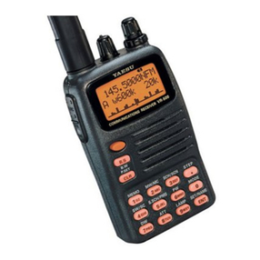
Other Yaesu Receiver manuals

Yaesu
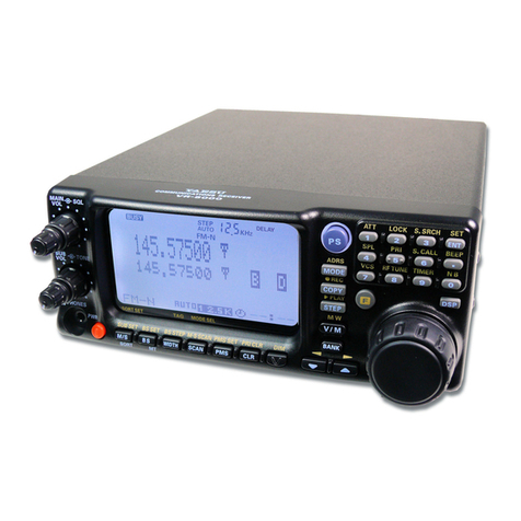
Yaesu VR-5000 User manual

Yaesu
Yaesu FRG-8800 User manual

Yaesu
Yaesu FRG-7700 User manual

Yaesu
Yaesu FR-100-b User manual

Yaesu
Yaesu FT-710 Technical manual

Yaesu
Yaesu FRG-8800 User manual

Yaesu
Yaesu FRG-100 Manual

Yaesu
Yaesu FL-101 User manual

Yaesu
Yaesu VR-500 User manual

Yaesu
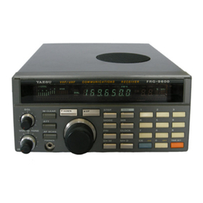
Yaesu FRG-9600 User manual