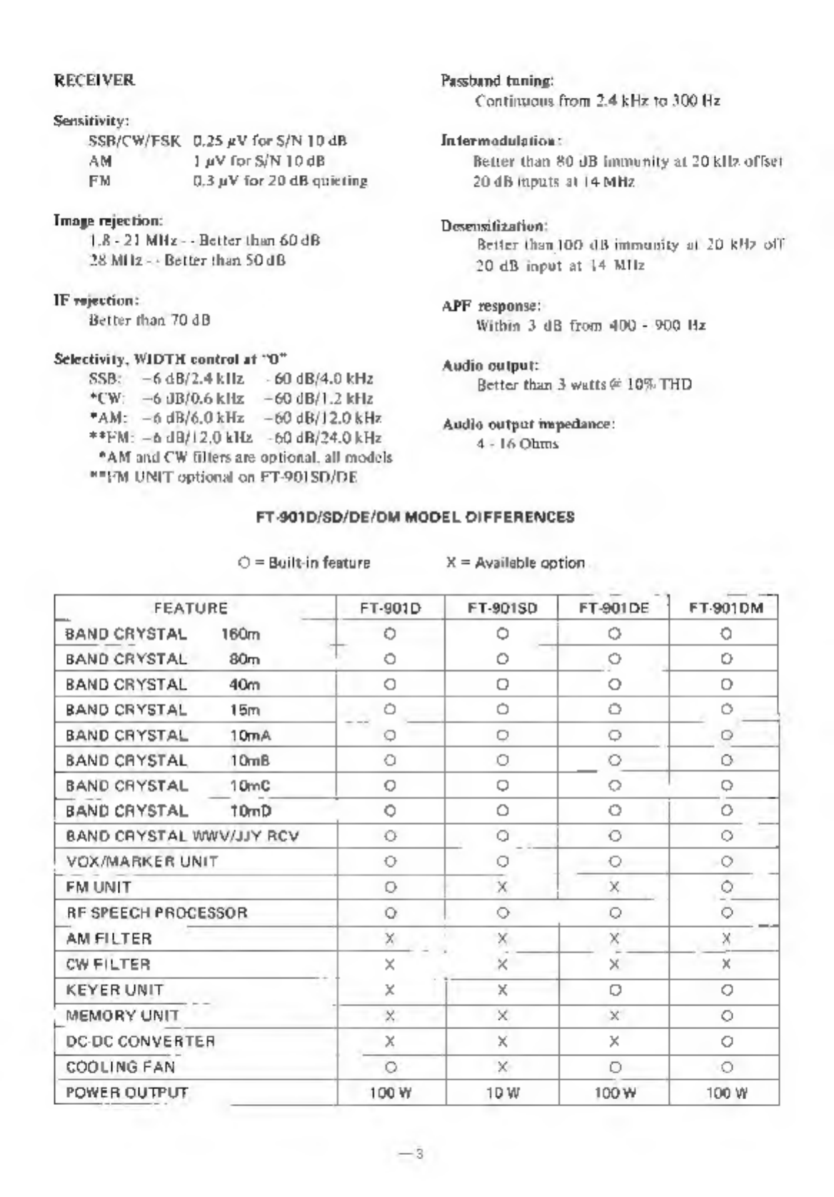
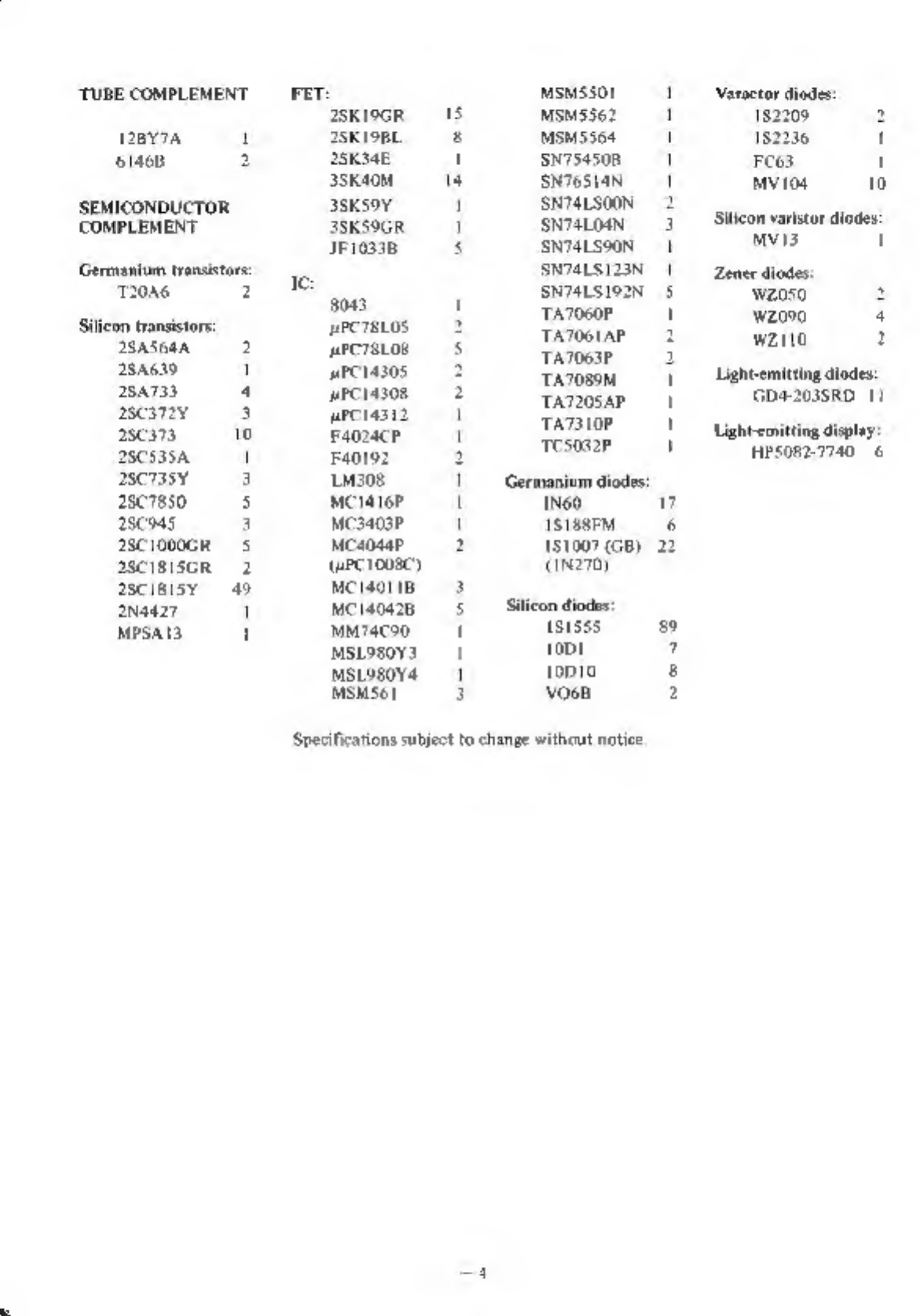
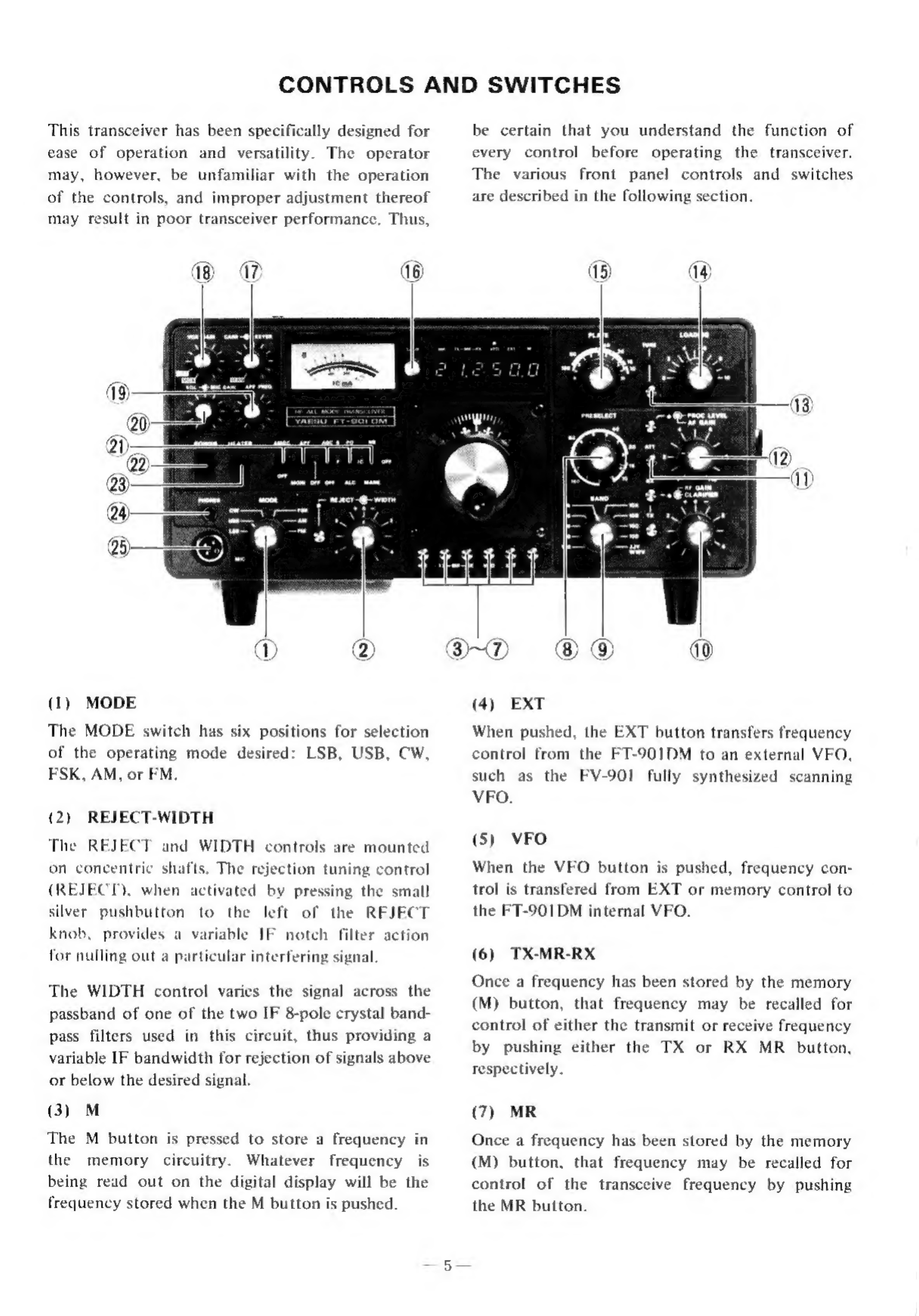
Yaesu FT-901DM User manual

INSTRUCTION
MANUAL
FT-901DM
YAESU
MUSEN
CO.,
LTD.

TABLE
CONTENTS
GENERAL
SPECIFICATIONS
CONTROLS
AND
SWITCHES
REAR
APRON
CONNECTIONS.
.
INSTALLATION
OPERATION
BLOCK
DIAGRAM.
es
CIRCUIT
DESCRIPTION
MAINTENANCE
AND
ALIGNMENT.

ALL
MODE
HF
TRANSCEIVER
FT-901DM
GENERAL
DESCRIPTION
The
FT-901DM
is
a
precision
engineered,
high-
performance
HF
transceiver
of
advanced
design,
providing
all
band
coverage
(160
-
10
meters)
on
all
modes
of
operation:
LSB,
USB,
CW,
FSK,
AM,
and
FM.
This
transceiver
operates
at
an
input
power
of
180
watts
SSB/CW
and
80
watts
on
AM,
FM,
and
FSK.
Advanced
features
include
PLL
(Phase
Locked
Loop)
frequency
derivation,
digital
plus
analog
frequency
readout
with
large
display
LED
digits,
a
built-in
Curtis
8043
IC
electronic
keyer,
and
memory
frequency
control
circuitry.
State-of-the-
art
receiver
performance
features
include
rejection
tuning,
dual-filter
variable
IF
bandwidth
tuning.
and,
for
CW.
an
audio
peak
filter
(APF)
for
un-
surpassed
rejection
of
unwanted
signals.
Other
built-in
features
include
VOX,
semi-break-in
CW
with
sidetone,
25
kHz
calibrator,
advanced
noise
blanker,
RF
speech
processor.
and
a
20
dB
RF
attenuator
for
protection
against
receiver
overload.
All
circuits,
except
the
transmitter
driver
and
final
amplifier
stages,
are
solid
state,
utilizing
modern
plug-in
printed
circuit
boards,
thus
per-
mitting
easy
maintenance.
The
FT-901DM
transceiver
is
entirely
self-con-
tained,
requiring
only
an
antenna
and
power
source
for
operation.
For
base
station
operation,
AC
power
voltages
of
100/110/117/200/220/234
VAC
may
be
chosen,
though
the
unit
normally
is
sup-
plied
with
117
volt
capability.
A
DC-DC
converter
unit
provides
for
mobile
or
portable
operation.
Selection
of
AC
or
DC
power
source
is
automati-
cally
made
when
the
proper
line
cord
is
inserted.
For
mobile
operation
a
separate
switch
is
provided
on
the
front
panel
to
turn
off
the
tube
heaters
while
in
the
receive
mode.
With
the
heaters
off,
current
consumption
is
only
1.1
amp.
Among
the
available
options
on
economy
models
FT901D/SD/DE
are
the
memory
unit,
the
keyer
unit,
the
DC-DC
converter,
the
FM
unit,
and
the
cooling
fan.
Optional
equipment
on
all
models
are
the
600
Hz
CW
filter
and
the
6
kHz
AM
filter.
The
entire
FT-901DM
transceiver
weighs
approxi-
mately
18
kg.,
and
is
342
mm
wide,
154
mm
high,
and
324
mm
deep.
A
diecast
front
panel
and
heavy-duty
case
provide
maximum
protection
against
damage
from
shock
and
vibration
during
travel
use.

SPECIFICATIONS
GENERAL
Frequency
coverage:
160m
18-20
Mile
80m
35-40.
MHz
410
70-75
MHz
20m
14.0-18,5
MHz
15m
21,0-21.5
Mz
Toma
28,0-
28.5
MHz
10m
28:5-29.0MHz
Vom
29,0-
29.5
MHz
1mb
29.5.
29.9
Mile
WWV/LIY
15.0-15.5
Milz,
RX
only
Power
requirements:
‘AC
100/{10/117/200/220/234
W,
$0}60
Ile
DC.
13.5
V,
negative
ground
(DC
option
FT-901D/SDIDF)
Power
consumption:
(FT-901DM/D/DE
ACIITV:
TOwatts
receive
(45
watts
HEATER
OFF)
320
watts
tansinit
(max)
DE
ILS
Vs
SA
receive
(TA
HEATER
OFF)
2A
transmit
(max)
(FT9018)
AC
IITV:
55
watts
receive
(4S
wats
EATER
OFF)
105
watts
tansmmit
(max)
DC
IRS
V:
3K
A
receive
(08
A
HEATER
OFF)
7.5.8
transmit
(mux)
Size
342
(W)
x
154
(HD)
x
324
(0D)
mm
Weight:
Ike
TRANSMITTER
Emission:
LSB,
USB
(AR).
CW
CAT),
AM
(ASD),
FM.
(£3)
(option
FT-901SD/DE).
FSK
(1)
PA
input
power:
FT-901DM/D/DE
SSB/CW.
180
watts
DC
AN/ESK/FM.
0
watts
DC
F901sD
SSB/CW/FSK/FM:
20.watts
DC
aN.
S
watts
DC
Carrer
suppression:
Better
than
40
db
wanted
sideband
suppression:
Better
than
40.48
1000
He
Spurious
radiation:
etter
than
40
UR
below
rated
output
‘Transmitter
frequency
response
300-2700
He
(~6
db)
‘Third
order
distortion
produets:
Beiter
than
31
dB
below
rated
ourput
‘Transmitter
frequency
stability
tess
thin
300
Hp
after
10
exinute
wasmup,
fess
than
100
1b
after
30
minute
wartnup,
Negative
feedback:
dB
at
14
MHZ
Modulation:
ABE:
Balanced
mods
ABI:
Amplitude
modulation
of
«
low
power
Pa:
Variable-reacta
©
frequeney.
moguls
tion,
mas.
deviation
#5
kH2
(F3
fea:
ture
optional
on
FT-9O1SD/DE)
Antenna
output
impedance:
50-15
Ohms.
unbalanced
Microphone
input
impedance:
500
-
600
Ohms

RECEIVER
Sensitivity
SSBICW/FSK
0.25
4V
for
SIN
10
dB
AM
TAY
for
SIN
1048
a
0.3
AV
for
20 48
gvieting
Image
rejection:
18-21
Miz
Better
than
60.48
28
Mila
--
Better
than
SOaD
IF
rejection
‘etter
than
70
dB
‘Selectivity,
WIDTH
control
at
“0
SSB:
—60B/2.4kI2
60
dB/4.0
kHz
CW:
6
UB/O.6
KHz
60
0B/1.2
Hz
TAM:
—6
dB/6.0kH2
60
dB/12.0kHr
AEM:
68/120
kHz
-60.dB/24,0
kH2
AM
and
CW
filters
are
optional
all
models
**EM
UNIT
optional
on
FT-901SD/DE.
Passband
toning:
‘Continuous
from
2.4
kHe.
10
300
He
Intermodulation
Better
than
80
UB
jmmunity
at
20
kite
offset
20.48
mpuis
at
14
Mttz
Desensitization:
Better
than
100
JB
immunity
at
20
kM?
off
20
dD
input
at
14
MItz
APF
response
Within
3
eB
from
400
-
900
Hz
Audio
outpur:
Better
than
3
watts
@
10%
THD
Audio
output
impedance:
4-16 0hms
FT-901D/SD/DE/OM
MODEL
DIFFERENCES
Buitein
feature
X=
Available
option
i
FEATURE
[F801
|
Frs0is0
|
Frsoine
|
Freoion]
[Bano
caYsTAt
160m
[0
°
|
o
°
BAND
CRYSTAL
80m
° °
2
©
BAND
CRYSTAL
40m
© 9
@
°
BAND
CRYSTAL
16m
3 6
5
©
BAND
CRYSTAL
10mA
-_:
°
°
°
BAND
CRYSTAL
108
ql
3
©
©
BAND
CRYSTAL
10m
© ©
5
©
[BAND
cAYSTAL
_—10n0
©
°
©
5
BAND
CRYSTAL
WWV/UY
RCV
©
om
©
oJ
VOXIWARKER
UNIT
°
°
e
o
|
[em
unit
°
x x
2
RF
SPEEGH
PROCESSOR
oe
70
° 6
[aM
FILTER
x x x
7]
OW
FILTER
x
x
x
=
EYER
UNIT
x x
3 3
[MEMORY
UNIT
x
x
x
o
COC
CONVERTER
x x
x
3
COOLING
FAN
o
x
oO
o
POWER
OUTPUT
Too
w
iow
woow
|
T00w

“TUBE
COMPLEMENT
12By7A
1
61468
2
SEMICONDUCTOR
COMPLEMENT
Germanium
transistors:
T20A6
2
Silicon
transistors
2SASGAA
2
28nei9
1
2sa733
4
DcsTY
3
2scs73,
10
28C535A
2SCTSSY
3
28C7850
5
28945
a
2sc1o00GR
5
28C1818GR
2
ascisisy
49
2Na827
1
MPSAI3
1
Ic
25KI9GR
2sKI9RL
2SK34E
38K40M
38K59Y
39KS9GR
110338
8083
PCTELOS
PCTSLOS
HPC14305
HPCI4308
wPciasi2
F4024cP
40192
LM308
MCI416P
MC3403P
Mcao4aP
(upc
1008)
MC
1401
1B
MC
140428
MMT4C90
MSLUSOY3
MSLOBOY4
MSMS61
MsMssor
MSM5562
MSM5364
SN754508
SN76S14N
SN74LSOON
SN74LO4N
SNT4LSOON
SNDALS]23N
SN7ILS192N
‘TATO60P
TATOGLAP
TA7063P
TA7059M
TA7205AP
TA7310P
‘Te5032P
1
1
1
1
1
a
1
Hl
5
'
1
1
1
'
Germanium
diodes:
1N60
1S
188M
151007
(GB)
INTO)
Silicon
diodes:
18158589
toot
7
top10
5
voos
2
Specifications
subject
to
change
without
notice
Varactor
diodes:
182209
182236
'
F
C63
t
MVIog
10
Silicon
vatistor
diodes:
MVI3
t
Zener
diodes:
wz0s0
Wz090
wzit0
Light-emitting
diodes:
GD4-2038RD
11
Lightemitting
display’
HPS082-7740
6

CONTROLS
AND
SWITCHES
This
transceiver
has
been
specifically
designed
for
ease
of
operation
and
versatility.
The
operator
may,
however,
be
unfamiliar
with
the
operation
of
the
controls,
and
improper
adjustment
thereof
may
result
in
poor
transceiver
performance.
Thus,
(1)
MODE
The
MODE
switch
has
six
positions
for
selection
of
the
operating
mode
desired:
LSB,
USB,
CW,
FSK,
AM,
or
FM.
(2)
The
REJECT-WIDTH
REJECT
and
WIDTH
controls
are
mounted
on
concentric
shafts.
The
rejection
tuning
control
(REJECT),
when
activated
by
pressing
the
small
silver
pushbutton
left
the
REJECT
knob,
provides
a
variable
IF
notch
filter
action
for
nulling
out
a
particular
interfering
signal
to
the
of
The
WIDTH
control
varies
the
signal
across
the
passband
of
one
of
the
two
IF
8-pole
crystal
band-
pass
filters
used
in
this
circuit,
thus
providing
a
variable
IF
bandwidth
for
rejection
of
signals
above
or
below
the
desired
signal.
(3)
M
The
M
button
is
pressed
to
store
a
frequency
in
the
memory
circuitry.
frequency
is
being
read
out
on
the
digital
display
will
be
the
frequency
stored
when
the
M
button
is
pushed.
Whatever
wy
7)
be
certain
that
you
understand
the
function
of
every
before
operating
the
transceiver.
The
various
front
panel
controls
and
switches
are
described
in
the
following
section.
control
®
(4)
EXT
When
pushed,
the
EXT
button
transfers
frequency
control
from
the
FT-901DM
to
an
external
VFO,
such
as
the
FV-901
fully
synthesized
scanning
VFO.
(5)
VFO
When
the
VFO
button
is
pushed,
frequency
con-
trol
is
transfered
from
EXT
or
memory
control
to
the
FT-901DM
internal
VFO.
(6)
TX-MR-RX
Once
a
frequency
has
been
stored
by
the
memory
(M)
button,
that
frequency
may
be
recalled
for
control
of
either
the
transmit
or
receive
frequency
by
pushing
either
the
TX
or
RX
MR
button,
respectively.
(7)
MR
Once
a
frequency
has
been
stored
by
the
memory
(M)
button,
that
frequency
may
be
recalled
for
control
of
the
transceive
frequency
by
pushing
the
MR
button.

(8)
PRESELECT
This
control
pretunes
the
signal
cireuils
for
bath
transmit
and
receive.
The
PRESELECT
circuit
Drowites
continuous
peemeability
tuning
through
‘ur
the
Frequency
range
of
the
bransecive
1)
HAND,
Ihe
BAND
switch
provides
selection
of
the
band
10
through
10
meters
plus
WWV/JIY
Arecrive
nly
Uosire,
(10)
RF
GAIN/CLARIFIER
The
RF
GAIN
und
CLARIFIER
controls
are
hnowted
on
concentsic
shafts,
The
RF
GAIN
keonisol
provides
manual
contro!
of
the
gait
eels
ff
the
RF
and
IF
amplifies
on
receive,
‘The
CLARIFIER
control
allows
mana
offset
of
ELS
Kllz
of
either
the
ttansmit
oF
receive
tre
{queney.
Selection
of
transmit
oF
reecive
clarifier
ie
hy
the
two
silver
pushbuttons
to
the
left
of
the
CLARIFIER
contol
an
atr
The
ATT
(RF
antequator)
button
provides
inser
lion
of
4
20
dB
attenuator
in
the
incoming
signal
path
fa
minimize
recviver
cross
modulation
eaused
by
extremely
strong
focal
signa,
(12)
PROC
LEVELJAF
GAIN
‘The
PROC
LEVEL
and
AF
GAIN
controls
are
‘mounte
on
concentric
shafts.
The
PROC
LEVEL
contra!
allows
manual
contro!
of
the
outpat
level
fof
the
RF
speech
processor.
The
processor
is
actuated
by
pressing
the
silver
pushbutton
to
the
left
ofthe
PROC
LEVEL
contrat
‘The
AF
GAIN
control
adjusis
the
audio
output
level
at
the
speaker
and
phone
Jack.
Clockwise
rotatinn
increases
the
audio
output
(13)
TUNE
This
pushbutton,
when
depressed,
places
the
trans
milter
inthe
“Tune”
condition
for
ten
seconds
for
tuning
purposes.
After
ten
seconds,
the
train
ceiver
is
returned
to
the
receive
mode
so
a
to
al_ampitier
mbes
caused
‘ime
during
toneup.
prevent
damage
to
the
by
cxoessive
“key
down
(14)
LOADING.
This
control
tunes
the
output
eireuit
of
the
ps
net-
Work
to
match
the
antenna/feedtine
impedance.
(15)
PLATE
This
control
tunes
the
plate
circuit
of
the
final
amplifier
(16)
CALIB,
When
the
MARK
switeh
is
activated,
the
CALIB
knob
provides
manual
vontrol
for
zeroing
the
calibration
of
the
digital
display
with
he
eal
brator
signal
(17)
CARR/KEYER
The
CARR
and
KEYER
controls
are
mounted
fon
concentric
shafis.
The
CARR
control
varies
the
amount
of
cartier
in
the
CW,
AM,
FSK.
and
FM
models
af
operation
‘The
KEVER
contiol
varies
the
speed
of
the
builtin
Curtis
8043
IC
electronic
keyer,
(18)
VOX
GAIN
This
control
selects
MOX/PTT/VOX
transmitter
relay
control
as
well
as
adjusting
the
sensitivity
of
the
VOX
circuitry.
The
PIT
position
provides
pust-io-alk
operation
from
4
microphone
PTT
switch
oF a
footswitch,
The
MOX
position
provides
‘manual
transmit,
It
must
be
returned
to
the
PTT
position
For
receiver
recovery
(19)
APF
FREQ.
‘This
knob,
when
actuated
by
cuming
on
the
APF
switch,
provides
manual
control
for
peaking
the
auitio
peak
filter
(APE)
citeuit
on
the
desited
signal.
This
control
witl
find
its
chief
wsefulness
‘on
CW.
because
is
bandwidth
is
much
tow
marrow
for
normal
SSB
reveption.
(20)
SOLMIC
GAIN
‘The
SQL
and
MIC
GAIN
controls
are
mounted
on
concentric
shafts,
The
SOL
control
sets
the
squeleh
threshold
level
for
FM
reception,
‘The
MIC
GAIN
control
varies
the
audio
lev!
from
the
microphone
amplifier
stage,
The
control
has
sulficient
range
to
permit
the
use
of
any
low
inv
edance
(50
-
600
Ohm)
erystal
or
dynamic
‘microphone.
Clockwise
rotation
increases
the
level
of
output
from
the
microphone
amplifier
stag,
(21)
FUNCTION
SWITCHES:
AMGC,
APF/MONI,
AGC,
PO/IC/ALC,
and
NB/MARK
‘The
AMGC
switeh
activates
+
microphone
gain
threshold
circuit
which
requires
a
particular

minimum
input
level
from
the
microphone
to
trigger
the
microphone
amplifier.
Low-level
back-
ground
noise
will
not
activate
the
transmitter
with
the
AMGC
in
operation.
This
circuit
may
be
considered
a
“microphone
squelch”
system.
The
M
GAIN
control
functions
normally
with
the
AMGC
system
in
operation.
When
the
APF/MONI
switch
is
in
the
APF
posi-
tion,
the
audio
peak
filter
(APF)
circuitry
is
activated.
The
exact
frequency
of
the
audio
peak
is
set
by
the
APF
FREQ
knob.
When
this
switch
is
placed
in
the
MONI
position,
monitor-
ing
of
the
microphone
level
may
be
accomplished
for
operator
convenience
or
tape
recording
both
~
sides
of
a
QSO.
In
the
CW
mode,
CW
sidetone
will
be
heard
regardless
of
the
position
of
the
APEF/MONI
switch.
The
AGC
switch
controls
the
length
of
the
re-
covery
time
for
the
receiver
AGC
circuitry.
This
switch
provides
slow
or
fast
recovery,
and
will
also
turn
off
the
AGC
if
desired.
The
PO/IC/ALC
switch
will
hereafter
be
referred
to
as
the
METER
switch.
In
the
PO
position,
relative
transmitter
output
power
can
be
observed.
In
the
IC
position,
transmitter
final
amplifier
cathode
current
may
be
measured.
In
the
ALC
position,
transmitter
ALC
voltage
may
be
read.
When
the
FT-901DM
is
in
the
receive
mode,
the
meter
functions
as
an
“S”
meter.
The
NB/MARK
switch
provides
for
actuation
of
either
the
Noise
Blanker
(NB)
or
crystal
calibrator
(MARK),
The
marker
oscillator
can
produce
cali-
bration
signals
at
intervals
of
either
25
kHz
or
100
kHz
by
proper
positioning
of
a
switch
inside
the
cabinet.
(22)
POWER
This
is
the
main
on/off
switch
for
the
transceiver.
In
the
OFF
position,
the
memory
circuits
are
disabled,
so
that
when
the
transceiver
is
turned
to
ON
again,
the
memory
circuits
will
have
to
be
reset.
(23)
HEATER
With
the
HEATER
switch
in
the
down
position,
the
transmitter
tube
heaters
are
turned
off.
This
reduces
battery
drain
to
1.1
amp
and
thus
permits
long
periods
of
listening
without
excessive
battery
drain.
Placing
this
switch
in
the
up
position
pro-
vides
supply
voltage
to
the
tube
heaters,
and
after
30
seconds
of
warmup
the
transmitter
is
ready\for
operation.
This
switch
operates
in
both
the
AC
and
DC
modes.
SS)
(24)
PHONES
This
is
a
standard
1/4”
phone
jack
for
accom-
modation
of
headphones.
The
internal
speaker
is
disabled
when
headphones
are
plugged
into
this
jack.
(25)
MIC
This
four-conductor
jack
microphone
plug
for
microphone
input
as
well
as
for
PTT
actuation.
accommodates
—
the
Mic
plug
Headphone
plug

REAR
APRON
CONNECTIONS
O®
(1)
GND
Threaded
lug
for
ground
connection.
la
(2)
RF
OUT
Signal
frequency
output
from
the
driver
stage
may
be
obtained
at
this
jack
for
use
with
optional
equipment,
such
as
the
FTV-901R
VHF/UHF
transverter.
(3)
ANT
Coaxial
connection
for
antenna.
(4)
POADJ
Sets
PO
meter
sensitivity.
ond
receiver
receives
its
antenna
connection
through
thisjack.
ACC
Cessory
socket.
Provides
access
to
transceiver
operating
voltages
and
relay
contacts.
—————
(7)
KEY
Three-conductor
jack
paddle
or
external
key.
for
connection
to
keyer
(8)
EXT
VFO
Connections
for
external
VFO.
OH/ODO®
w
7)
\
5
————
a
“MU
(
REC.)
(9)
FUSE
;
Fuse
holder
requires
5
amp
fuse
for
117
volt
or
*
3
amp
fuse
for
220
volt
operation.
For
12
volt
DC
operation,
a
20
amp
fuse
power
cable.
installed
in
the
When
replacing
fuses,
be
certain
to
install
a
fuse
of
the
proper
rating.
The
warranty
does
not
cover
damage
caused
by
improper
fuse
replacement.
(10)
POWER
Power
receptacle.
Both
AC
and
DC
cables
are
Std€tone
output
for
second
receiver
(if
used).
—
(12)
IF
OUT
2
Wide-bandwidth
8.9
MHz
IF
signal
for
connection
to
a
spectrum
analyzer,
ete.
(13)
PATCH
Speech
input
terminal
for
phone
patch
connection,
Impedance
is
500
ohms.
(14)
A-PRIP
ntj-tfip
input
from
second
receiver
(if
used).
——
(15)
SP
Audio
output
is
provided
at
this
jack
for
an
ex-
ternal
speaker.
Output
impedance
is
4
ohms,
and

the
internal
speaker
will
be
disabled
when
plug
is
inserted.
(16)
PTT
This
jack
may
be
used
for
external
actuation
of
the
transmitter.
As
an
example,
a
footswitch
may
be
connected
to
this
jack
to
provide
remote
con-
trol
of
the
transmitter
relay,
leaving
the
operator’s
hands
free
for
writing
and
tuning
purposes.
(17)
FSK
Input
from
the
FSK
terminal
may
be
made
through
this
jack.
The
FT-901DM
is
set
up
for
170
Hz
shift.
(18)
IFOUT
1
Narrow
bandwidth
8.9
MHz
IF
output
is
avail-
able
for
use
with
an
IF
monitorscope,
etc.
(19)
REMOTE
Provides
switched
13.5
VDC
for
relay
control
for
external
low-pass
filter
units,
etc.
As
the
band-
switch
is
rotated,
13.5
VDC
will
appear
at
various
pins
on
the
REMOTE
jack.
Use
a
VOM
to
deter-
mine
the
proper
pin
for
the
band
in
use.
por
—
oe
nee
7
oc
ae
“Se
«
Van
External
speaker
ACC
plug
Pin
plug
Cooling
fan

INTERCONNECTIONS
430MHz
ANTENNA
144MHz
ANTENNA
|
SOMHz
ANTENNA
=F
a
|||]
—10=

INSTALLATION
This
transceiver
is
designed
to
be
a
single-unit
station
for
fixed,
portable,
or
mobile
operation.
Consequently,
power
supply
connections
provid-
ing
for
operation
from
a
variety
of
source
voltages
are
available.
This
system
provides
the
flexiblity
required
for
changing
locations
or
quick
moves
from
fixed
to
mobile
operation.
BASE
STATION
INSTALLATION
The
FT-901DM
is
designed
for
use
in
many
areas
of
the
world
using
supply
voltages
that
may
differ
from
the
operator’s
local
supply
voltage.
For
this
reason,
be
sure
that
the
voltage
marked
on
the
rear
of
the
transceiver
agrees
with
the
local
AC
supply
voltage.
THIS
INSPECTION
MUST
BE
MADE
BEFORE
CONNECTING
THE
AC
POW-
ER
CORD
TO
THE
POWER
OUTLET.
CAUTION
PERMANENT
DAMAGE
WILL
RESULT
IF
IM-
PROPER
AC
SUPPLY
VOLTAGE
IS
APPLIED
TO
THE
TRANSCEIVER.
The
transceiver
should
be
connected
to
a
good
earth
ground,
The
ground
lead
should
be
made
with
a
heavy
braid
wire
and
should
be
connected
to
the
GND
terminal
on
the
rear
apron
of
the
transceiver.
We
do
not
recommend
the
use
of
power
con-
nectors
other
than
the
ones
supplied
by
Yaesu.
If
a
rig
brought
in
for
servicing
is
blowing
fuses
every
time
you
plug
it
in,
check
to
make
sure
that
no
“improvements”
have
been
made
to
the
power
cord
through
substitution
of
or
modification
to
the
power
connector,
For
base
station
installation,
the
only
important
consideration
that
need
be
made
is
to
ensure
adequate
circulation
around
the
unit.
Do
not
place
books
or
papers
on
or
around
the
cabinet,
nor
should
the
unit
be
placed
on
top
of
another
heat-generating
device
such
as
a
linear
amplifier.
Avoid
heat
ducts
and
window
locations
which
are
exposed
to
the
hot
sun,
and
you
will
keep
your
transceiver
running
at
full
speed
for
a
long,
long
time.
Be
certain
to
ground
the
transceiver
through
a
heavy,
braided
cable
less
than
10
feet
long.
Cold
water
pipes
in
newer
houses
probably
are
unsatis-
factory
as
grounding
posts;
it is
much
better
practice
to
use
a
system
of
one
or
more
ground
rods,
with
the
ground
line
securely
bonded
to
the
ground
system.
MOBILE
INSTALLATION
(Note:
The
DC-DC
converter
described
herein
is
built-in
on
the
FT-901DM,
and
is
an
available
option
on
the
FT-901D/SD/DE
models)
The
FT-901DM
will
operate
satisfactorily
from
any
13.5
Volt
DC
negative-ground
battery
source
by
connecting
the
DC
power
cord
to
the
rear
panel
receptacle.
For
under-dash
mounting,
a
special
mobile
mounting
bracket
is
available
from
your
dealer.
In
mobile
installations
the
trans-
ceiver
should
be
suited
away
from
heater
ducts.
No
special
precautions
need
be
observed
if
ade-
quate
ventilation
spaces
is
available.
A
minimum
of
two
inches
of
air
space
above
the
cabinet
top
and
on
all
sides
is
recommended
to
allow
proper
air
flow
around
the
cabinet.
Never
stack
other
units
above
or
below
the
transceiver
since
the
accumulated
heat
from
both
units
could
cause
damage.
The
transceiver
requires
an
average
of
14
amps
on
transmit,
with
20
amps
on
voice
peaks,
The
DC
power
cable
comes
equipped
with
a
20
amp
fuse.
When
making
connections
to
the
car
battery,
be
absolutely
certain
that the
RED
lead
is
con-
nected
to
the
positive
(+)
terminal
and
the
BLACK
lead
is
connected
to
the
negative
(—)
terminal.
Reversed
connections
could
permanently
damage
the
transceiver.
ury]
lsocxe
r
ruse
Fuse
mOLOER
woLoeR

The
BLACK
lead
should,
preferably,
run
directly
to
the
negative
terminal
of
the
battery.
Using
the
car
frame
as
a
negative
connection
or
connecting
the
RED
lead
to
a
positive
point
such
as
the
ig-
nition
switch
places
the
transceiver
in
the
same
current
path
as
noise-creating
devices,
thus
failing
to
take
advantage
of
the
filtering
action
of
the
battery.
The
power
cable
should
be
kept
away
from
ignition
wires
and
should
be
as
short
as
possible
to
minimize
voltage
drop
and
to
provide
a
low
impedance
path
from
the
transceiver
to
the
battery.
Before
connecting
the
power
cable
to
the
trans-
ceiver,
check
the
battery voltage
with
the
engine
running
(battery
charging).
If
the
voltage
exceeds
15
Volts
DC,
the
regulator
should
be
readjusted
so
that
the
highest
charging
rate
does
not
ex-
ceed
15
Volts.
The
transceiver
should
always
be
switched
OFF
while
the
car
engine
is
being
started
to
prevent
voltage
transients
from
damaging
power
supply
components.
Width
=
"1"
ANTENNA
CONSIDERATIONS
The
FT-901
transceivers
are
designed
for
operation
using
an
antenna
system
presenting
a
50-75
ohm
resistive
load
at
the
antenna
jack.
Amateur
instal-
lations
seldom
meet
this
requirement
over
the
entire
spread
of
every
band,
but
the
final
amplifier
pi
network
is
sufficiently
forgiving
to
allow
for
minor
deviations
from
the
target
figure.
However,
significant
departures
from
the
50-75
ohm
range
will
result
in
seriously
degraded
transceiver
per-
formance.
If
an
open-wire
feedline
is
used,
or
if
the
input
impedance
of
the
antenna
system
presents
a
very
high
or
very
low
impedance
at
the
coaxial
input,
some
sort
of
antenna
tuner
must
be
used
to
pro-
vide
a
SO
-
75
Ohm
unbalanced
feedpoint
for
the
transceiver.
For
mobile
operation,
most
of
the
commercially-
available
antennas
on
the
market
will
provide
good
results
if
care
is
taken
to
tune
the
antenna
for
minimum
SWR.
The
outer
conductor
of
the
coaxial
cable
should
be
securely
grounded
to
the
automobile
chassis
at
the
antenna
mount.
Wssu
cu
Rejection
Tuning
Action
SSB,
CW
SSB
Filters
Filter
10
7
|
‘
f
11h)
{|
to=400Hz
im
<2
to=600112
‘ompiorts
oe
1
_
APF
Action
—12—

OPERATION
“The
tuning
procedure
for
this
transceiver
is
not
complicated.
However,
care
should
be
exercised
when
tuning
so
that
peak
performance
of
the
‘equipment
is
scoured.
The
following
paragraphs
describe
the
procedure
for
receiver
and
transmitter
eration
INITIAL
CHECK,
Before
connecting
the
trunsceiver
to
4
power
source,
carefully
examine
the
unit
for
any
visible
damage,
Check
that
all
modules
are
firmly.
in
place
and
that
the
conteels
and
switches
are
of-
erating
normally.
Make
sure
that
tke
voltage
spe-
cifcation
marked
on
the
rear
panel
matches
your
supply
voltage,
and
that
the
line
fase
oo
the
rear
Panel
matches
the
supply
voltage;
for
117
VAC.
use
a
S
ump
fuse,
and
for
220
VAC
use
a
3
amp
fuse,
For
DC
operation
fuse
holder
is
installed
in
the
DC
cable,
and
a
20
amp
fuse
should
be
installed
here
FREQUENCY
SELECTION
Frequency
readout
for
the
FT-201DM
inciy
booth
analog
and
digital
readout,
The
analog
reud-
‘out
dial
shows
calibrations
at
the
100
kHz
and
10
kHz
points,
and
is
marked,
as
well,
ia
1
kEl2
increments
for
fine
tuning.
The
digital
readout
tisplays
all
digits
of
the
operating
frequency,
with
resolution
down
to
100
Hz
accuracy
RECEIVE
OPERATION
(1)
Preset
the
controls
and
switches
as
indicated
POWER...
.OFF
HEATER...
OFF
VFO
Switch
depresed
VOX
GAIN,
.
PTT
position
RF
GAIN.
Fully
clockwise
Adjust
subsequently
for
com
fortable
level
Desiced
band
Desired
mode
BAND.
MODE
PRESELECT.
.Desired
band
sexment
e
@)
a
o
oy
Turn
the
POWER
switsh
to
ON.
The
meter
will
Tight
up
snd
the
operating
frequency
will
be
displayed
on
the
dial
window.
Adjust
the
AF
GAIN
control
for
2
comfortable
listening
level,
and
adiust
the
PRESELECT
control
for
maximum
mesiver
nose
or
signal
level.
The
PRESELECT
control
may
require
repeaking
as
the
main
tuning
dial
Is
tuned
e108
the
band,
‘The
RX
CLARIFIER
may
be
usilized
if
the
received
signal
is
drifting,
Pushing
the
RX
button
and
rotating
dhe
CLARIFIER
control
will
provide
4
means
of
offsetting
the
receiver
Frequency
£2.5
kH2
without
clanging
the
transmitting
frequency.
“red
LED
indieator
will
Light
up
when
the
CLARIFIER
is
in
use
When
pubetype
noise
is
encountered,
the
NB
(Noise
lanker)
switch
should
be
acti=
vated,
providing
fective
suppression
of
this
type
of
nose
Rejection
of
adjacent-chanael
interference
may
be
accomplished
by
several
means.
The
REJECT
control
may
be
utilized
t0
place
a
steep-skirt
30
dB
noted
attenuation
on
any
interfering
signal
within
the
IF
pastband
‘The
WIDTH
control
vavies
the
center
fre-
queney
of
one
of
two
IF
filters
(the
other
is
fixed
and
presents
a
boundary
for
narrow
ing
the
passband).
Varying
the
WIDTH
com
trol
varias
the
IF
selectivity
from
approxi:
rately
300
Hz
to
2.4
kHz
(at
2.4
KH
the
WIDTH
controt
is
at
“O™
and
the
two
filters
have
the
stme
center
frequency).
Clockwise
rolalion
from
the
center
(°O")
position
makes
the
passband
narrow
toward
the
high
frequency
side,
while
counterclockwise
ro
{ation
narrows
the
passband
on
the
low
Frequency
sid.
For
CW
reception.
the
APF
(Audio
Peak
Filter)
may
be
activated.
This
filter
has
100
He
peak
bandwidih
with
very.
steep
skirts
so
as
to
provide
sinslesignal
reception
for
CW,
with
insertion
loss
of
less
than
1
dB
when
the
APF
conttol
is
tuned
exactly
ta
the
signal
frequency.
The
APF
FREQ
control
varies
the
peak
frequency
from
approximately
4400
Hz
fo
900
Itz.
The
operator
will
observe
that
the
APE
system
provides
a
significant

improvement
in
signalto-noise
ratio.
The
selectivily
of
the
APP
circuit
may
be
varied
hy
adisting
VRsy
ule
the
top
cover
(OY
For
extremely
strong
signals,
the
ATT
(RE
attenuator)
switch
may
be
presied
to
activate
220
di
attenuation
of
the
incowning
signal
This
should
prevent
any
chanee
of
overioat
Cf
the
receiver
front
end.
‘TRANSMITTER
TUNE-UP.
‘The
following
tune-up
procedure
must
be
per-
formed
prior
ta
commencing
operation
on
the
desired
mode:
LSB,
USB,
CW,
FSK,
AM,
ar
FM.
See
the:
paragraphs
relating
(0
the
specific
mode
after
basie
transmitter
tune-up
8
described.
Connect
a
dummy
loud
oF
matched
antenna
to
the
coaxial
fitting
on
the
rear
apron.
Preset
the
‘eantrals.as
Follows:
POWER
OFF
HEATER
OFF
CARK
Fully
counterclockwise
position
MICGAIN.
Folly
counteeslockwie
postion
ANG
OFF
METER
switch
IC
SELECT
VFO
(Depressed)
BAND
Desired
band
segment
USB
or
LSB
Desired
band
segment
Desired
band
segment
“To
position
show
in
table
PROC
OFF
(Not
depressed
TUNE
OF
(Not
depressed)
CLAR
TX...
.OFF
(Not
depressed)
VOX
GAIN...
PTT
position
‘Turn
the
POWER
and
HEATER
switches
to
ON,
From
cof
start.
allow
60
seconds
after
the
HEATER
switel
¢
turned
on
for
warm-up
of
the
transmitter
tubes.
Bo
certain
that
the
accessory
plug
is
inserted
in
the
accessory
plug
is
inserted
Jn
the
accessory
sockel;
without
this
plug
being
so
connected,
there
will
he
no
power
applied
ta
the
lube
heaters,
Heater
voltage
is
supplied
through
pins
1
and
2
of
the
accessory
socket.
LOADING
POSITIONS.
BAND
160
80
40
lon
|
Note:
LOADING
postions
are
aominsl.
Minor
variations
from
positions
shown
are
10
he
expected
Set
the
VOX
GAIN
control
to
MOX,
The
meter
will
now
read
final
amplifier
resting
exthode
current,
This
should
read
.05
(50
mA)
If
itis
not,
adjust
the
bias
eosteol
located
ander
the
top
cover
near
the
rear
of
the
sot,
Set
the
METER
switch
to
ALC
and
adjust
the
ALC
control
under
the
top
cover
for
full
seae
deflection
of
the
meter.
Return
the
meter
switeh
to IC
and
the
VOX
GAIN,
conttal
to
PTT.
Not:
On
the
PT-90ISD,
resting
exthode
‘current
showld
be
025
(25
mA).
PRE-TUNING
UMPORTANT
NOTE:
Subsequent
transmitter
tuning
utilizes
the
TUNE
button
instead
of
MOX
for
actuating
the
transmitter,
When
presse,
the
TUNE
button
causes
the
transmitter
to
be
act
vated
for
ten
seconds,
after
which
time
the
FT-
901DM
retums
t0
the
reecive
condition,
This
is
2
protective
feature
that
sould
not
be
nullified
by
use
of
the
MOX
eontrol.»
(1D)
Adjust
the
PRESELECT
control
for
maxi-
rum
reveiver
noise
evel
2)
Depress
the
TUNE
button,
Rotate
the
CARR
control
until
the
meter
reuding
rises
just
above
the
normal
idling
current
of
0S
(50
may,
B)
Adjust
the
PRESELECT
control
for
maxi-
‘urn
meter
indication,
Cavtion:
if
the
meter
reading
exceeds
1
(100
mA)
reduce
the
setting
of
the
CARR,
contrl.

(2)
Rotate
the
PLATE
control
for
a
minimum
meter
reading
dip”
in
final
amplifier
eallinde
current)
(5)
Push
the
TUNE
button
again
to
rote
the
transceiver
tothe
receive
condition,
FINAL
TUNING
Final
peak
runing
utlizes
the
relative
power
out
Dut
position
of
the
METER
switch,
At
full
cated
Power
inte
SO
Ohm
load,
the
meter
will
read
approximately
12
to.
2/3 ull
scale.
IF
the
PO
reading
is
too
igh
(olf
scale)
oF
too
low
(1/4
seale
fr
less}
and
the
load
impedance
is
very
dlose
10
50 Ohms,
the
PO
ADJ
control
on
the
rear
apron
may
be
adjusted
so
as
to
provide
1/2
to
2/3
seale
election
at
Fill
power,
Once
the
PO
meter
is
calibrated,
ofseale
meter
defections
are
the
result
of
reflected
power
dur
(0
high
SWR,
and
corrective
action
may
be
required
in
the
antenna
Final
fransmitter
peaking
is
deseribed
below.
(1)
See
the
METER
switch
to
the
PO
position
and
rotate
the
CARR
control
to
the
U1
o'clock
position
Press
the
TUNF
button
and
rotate
the
PRE:
SELECT
control
for
a
maximum
meter
reade
ing.
Press
the
TUNE
button
agsin
to
return
to
the
revive
condition,
(3)
Peess
the
TUNE
button
and
rotate
the
LOAD:
ING
control
for
a
maximum
meter
reading
Pres.
the
TUNE
button
agin
to
rerum
10,
the
receive
condition,
(4)
Poss
the
TUNE
button
and
rotate
the
PLATE
ontrol
for
s
maximum
meter
reading.
Press
the
TUNE
button
again
to
return
¢©
the
re
ceive
condition,
(3)
Repeat
steps
2
through
4,
advaneing.
the
CARR
control
approximately
2
units
for
teach
set
of
adjustments
untit
the
CARR
eon:
trot
is
fully
clockwise.
The
transmitter
is
now
tuned
for
maximem
power
output
(6)
Return
the
CARR
control
to
the
fully
coun-
lerelockwise
position,
Reluen
the
METER
switch
to
IC
With
Fomilisrity,
some
of
steps
2
=
4
may
be
per
formed
within
one
press
of
the
TUNE
button,
(aking
advantage
of
the
1second
timer.
The
operator
is
discouraged.
through.
from
excel
tthe
TOsccond
limitation
imposed
by
the
timer
Ghrough
use
of
the
MOX
pesition
oF
the
micro
phone
PTT
switch,
‘SSB
OPERATION
After
completion
of
the
above
tuning
procedure
sel
the
MODE
switch
to
USB
or
LSB
as
desired.
Set the
VOX
GAIN
control
to
PT
and
activate
the
inesmitter
by
pushing
the
microphone
PTT
switch
of
the
footswitch,
if
used.
While
speaking
in
@
normal
voioe
into
the
niieroniione,
sklvanes
the
MIC
GAIN
control
uatit
the
meter
kicks
down
{othe
midscale
of
the
greencolored
portion
of
the
meter
seale
Note:
When
the
METER
switch
is
set
to
16,
Voice
modulation
peaks
will
indicate
150
>
200
ma.
Actual
peak
evtrent.
however.
is
approximately
2
tines
the
indicated
valve,
To
set
the
sensitivity
of
the
VOX
system,
bevin
the
VOX
GAIN
control
in
the
PTT
position,
Advance
the
VOX
GAIN
and
speak
in
a
norma
voles.
The
VOX
GAIN
control
should
be
advanced
luntil
the
voice
aetuates
the
transmitter
(do
not
press
the
microphone
PTT
swite
or
footswitch.
i
tus,
during
this
adjustment
Set
the
antitip
potentiometer
under
the
top
over
10
the
minimus
point
whieh
prevents
the
speaker
outpul
from
tripping
the
VOX.
Do
not
lise
more
VOX
GAIN
nor
antitrin
than
necessary
Agiust
the
delay
potentiometer
under
the
top
tote
for
the
desired
release
time,
If
desired,
the
AMGC
circuit
may
be
activated
“This
circuit
ete
as
a
sierophone
squtleh
is,
it
initiates
4
theeshotd
for
mierop!
whet
microphone
amplifier
will
oceur.
This feature
permits
minor
noises
such
as
@
TV in
the
operating
oom
to
be
present
without
going
out
over
the
air,
Adjustment
of
the
AMGC
delay
time
is
made
by
w
control
under
the
top
cover.
RF
SPEECH
PROCESSOR
ADJUSTMENT
{AIL
models)
‘The
FT-90IDM
speech
processor.
when
properly
adjusted,
is
designed
(0
improve
the
intelligibility
threshold
at
the
receiving
em
by
increasing
the
averoge
SSB
power
oulput.
RE
clipping
is
applies
to
the
IP
signal,
which
is
then
Billered
to
remove
harmonics
and
out
of
band.
intermodulation
products

The
distortion
produced
by
RF
envelope
clipping
and
filtering
is
less
objectionable
than
that
caused
by
an
equivalent
amount
of
audio
clipping.
RF
clipping
causes
no increase
in
the
peak
power
output,
but
it
does
clip
the
peaks
of
the
voice
waveform
so
as
to
increase
the
average
power
output.
With
the
processor
switch
(located
immediately
to
the
left
of
the
PROC
LEVEL
control)
in
the
OFF
position
(not
depressed),
set
the
METER
switch
to
the
ALC
position.
Speaking
at
a
normal
level,
set
the
MIC
GAIN
control
to
the
level
where
the
meter
indication
stays
in
the
green
portion
of
the
meter
scale.
Press
the
processor
switch
and
adjust
the
PROC
LEVEL
control
to
the
position
where
the
ALC
indication
stays
in
the
green
por-
tion
of
the
meter
scale
while
speaking
in
a
normal
voice.
Optimum
setting
of
the
MIC
GAIN
and
PROC
LEVEL
controls
may
require
observation
of
the
transmitted
signal
using
an
oscilloscope.
PROCESSOR
ON
CW
OPERATION
Note:
The
Curtis
8043
IC
Keyer
Unit
is
built-in
on
the
FT-901DM/DE,
and
is
an
available
option
on
the
FT-901D/SD
models.
For
electronic
keyer
operation,
insert
a
three
con-
ductor
plug
attached
to
a
keyer
paddle
into
the
KEY
jack
on
the
rear
apron.
Keyer
speed
may
then
be
adjusted
by
varying
the
KEYER
control
on
the
front
panel.
—16—
For
straight
key,
bug,
or
external
electronic
keyer
use,
rotate
the
KEYER
control
fully
counter-
clockwise
into
the
click-stop.
The
desired
key
line
may
then
be
inserted
into
the
KEY
jack.
Refer
to
the
drawings
on
page
9
for
details
of
the
proper
key
line
plug
wiring.
The
transmitter
may
be
activated
on
CW
by
MOX,
PTT,
or
by
VOX
(semi-break-in)
as
desired.
The
key-up
voltage
across
the
key
terminals
is
7
volts,
while
the
key-down
current
is
1.5
mA,
so
most
external
electronic
keyers
may
be
used
with
the
FT-901DM
without
modification.
The
operator
may
select
any
power
output
desired
by
advancing
the
CARR
control
as
desired.
NOTE:
Insertion
of
the
key
plug
automatically
disconnects
the
bias
supply
to
the
PA
tubes.
Therefore,
bias
current
will
not
be
indicated
when
the
METER
switch
is
in
the
IC
position.
AM
OPERATION
AM
operation
of
the
transmitter
is
accomplished
by
setting
the
MODE
switch
to
the
AM
position
and
inserting
the
proper
amount
of
carrier
with
the
CARR
control.
After
completing
basic
transmitter
tune-up,
place
the
MODE
switch
in
the
AM
position.
Activate
the
transmitter,
and
rotate
the
CARR
control
until
the
meter
reads
.10
(100
mA)
in
the
IC
po-
sition
of
the
METER
switch.
While
speaking
into
the
microphone
in
a
normal
voice,
increase
the
MIC
GAIN
control
until
the
meter
indicates
very
slight
movement
with
voice
peaks.
Care
must
be
exercised
that
the
CARR
control
is
not
advanced
too
far.
Do
not
exceed
.10
(100
mA)
meter
indi-
cation
during
AM
operation
or
damage
to
the
transmitter
final
amplifier
tubes
may
result,
For
AM
reception,
an
AM
filter
is
available
as
an
option.
FSK
OPERATION
After
completing
basic
transmitter
tune-up,
place
the
MODE
switch
in
the
FSK
position.
The
FSK
terminal
input
may
be
connected
to
the
FSK
jack

on
the
rear
panel.
The
FT-901DM
is
set
up
for
170
Hz
shift,
and
the
shift
frequency
may
be
ad-
justed
somewhat
by
means
of
the
trimmer
capaci-
tors
located
under
the
top
cover.
The
CARR
con-
trol
must
be
adjusted
in
the
TUNE
position
for
not
more
than
100
mA.
Excessive
cathode
current
may
result
in
damage
to
the
final
amplifier
tubes.
Audio
output
from
the
transceiver
may
be
taken
from
the
SP
jack
in
the
rear
apron.
FM
OPERATION
Note:
The
FM
Unit
is
built-in
on
the
FT-901D/
DM,
and
is
an
available
accessory
on
the
FT-901SD/DE
models.
After
completing
the
basic
transmitter
tune-up,
set
the
CARR
control
for
100
mA
carrier
level
in
the
FM
mode.
Speak
into
the
microphone
in
a
normal
voice.
The
MIC
GAIN
and
PROC
LEVEL
controls
have
no
effect
in
the
FM
mode.
For
FM
reception,
the
SQL
control
on
the
front
panel
should
be
advanced
only
as
far
as
required
to
silence
background
noise.
When
adjusted
just
past
the
silencing
threshold,
the
squelch
circuitry
will
provide
noise-free
reception
with
maximum
sensitivity
to
weak
FM
signals.
DIAL
CALIBRATION
The
frequency
readout
of
the
FT-901DM
is
de-
signed
to
indicate
the
carrier
frequency.
Con-
sequently,
there
will
be
a
3
kHz
difference
be-
tween
USB
and
LSB.
When
calibrating
the
dial
and
digital
display,
the
CLARIFIER
switch
should
always
be
OFF.
(1)
For
SSB
calibration,
place
the
NB/MARK
switch
in
the
MARK
position
to
activate
the
internal
marker
signal
generator.
The
choice
of
25
kHz
or
100
kHz
marker
intervals
may
be
made
by
changing
the
position
of
switch
S601,
Which
is
located
on
the
VOX
unit.
As
the
main
tuning
knob
is
turned,
a
beat
note
will
be
heard
every
25
kHz
or
100
kHz,
depending
on
the
position
of
S¢o,
-
dial
and
secure
a
zero
beat
(lowest
pitch
‘fre-
quency)
with
the
marker
signal
nearest
the
desired
operating
frequency.
Q)
Tune
the
(3)
Turn
the
ribbed
calibration
ring
on
the
main
tuning
knob
shaft
to
calibrate
the
analog
scale
precisely
to
the
zero
or
25
kHz
point.
Adjust
the
CALIB
control
for
a
precisely
correct
reading
in
the
digital
window
(for
example,
14.225.0).
For
CW
calibration,
secure
a
zero
beat
as
above,
then
adjust
the
CALIB
control
until
the
digital
display
frequency
indication
is
705
Hz
higher
than
the
zero
beat
(for
example,
14.000.7).
Then
rotate
the
main
tuning
dial
to
secure
the
zero
or
25
kHz
reading
on
the
al
display
(14.000.0);
rotate
the
ribbed
calibration
ring
on
the
main
tuning
knob
shaft
to
align
the
analog
dial
precisely
with
the
calibration
mark
and
the
digital
display.
In
the
CW
mode,
to
repeat,
the
transmitter
(4)
(5)
carrier
frequency
is
the
frequency
being
displayed.
(6)
In
the
AM
and
FM
modes,
the
zero
beat
signal
is
not
available,
Place
the
WIDTH
con-
and
tune
the
dial
indication
the
trol
in
the
“O”
position,
for
maximum
S-meter
marker
signal
to
establish
point.
the
-
calibration
on
ny
Point
-2-3kHz
(AM.N)
5
6kHz
(AM.W)
10--12kHz
(FM)
meter
Deflection
Frequency
SELECT
SWITCHES/MEMORY
SYSTEM
OPERATION
(Note:
The
memory
unit
is
built-in
on
the
DM
model,
optional
on
the
D/SD/DE
models)
Frequency
control
of
the
FT-901DM
is
by
means
of
the
internal
VFO,
the
memory
unit,
an
ex-
ternal
VFO,
or
various
combinations
of
the
three.

Split.
memory
system
or
the
FV-901
synthesized
ses
hing
VFO.
The
switches
queney
control
may
be
obtained
with
th
wolved
in
frequency
‘control
are
a
follows
MR
RX
MR
vFo
EXT
Note:
‘This
button
recalls
the
memorized
fre-
queney
for
control
of
the
transceive
frequency.
‘This
button
recalls
the
memorized
fre
quency
for
control
of
the
transmit
fre
quency,
‘This
button
recall
the
memorized
fre
{quency
for
control
of
the
receive
fhe
quency,
Frequency
control
is
by
means
of
the
internal
VFO
as
controlled
by
the
main
tuaing
knob,
‘This
switch
selects
the
PV-901
synthe
sized
scanning
VEO
for
frequeney
or
‘tol
a8
follows:
with
the
EXT
and MR.
hnuttons
pushed,
transceive
frequency.
control
is
by
mieans
of
the
external
VFO.
With
the
EXT
and
TX
MR_
buttons
pushed,
the
extemal
VEO.
controls
the
trinsmil
frequency
while
the
internal
VEO
controls
the
receive
frequency.
With
the
EXT
and
RX
MR
buttons
Pushed,
the
extemal
VEO
controls
the
receive
frequeney
while
the
internal
VFO
controls
the
transmit
frequency
‘This
button
is
used
to
store
a
frequency
in-memory.
THE
FREQUENCY
DIS-
PLAYED
ON
THE
DIGITAL
READ-
OUT
WILL
BE
THE
FREQUENCY
STORED
WHEN
THE
M
BUTTON
IS
PRESSED,
When
the
M
button
is
pressed,
the
frequency
previously
stored
in
memory
will
be
destroyed.
When
the
power
is
turned
off,
the
frequency
is
Tost
from
memory.
Because
of
“round-olf
error”
the
disital
Aisplay
and
-memory
system
may
exhibit
2
100
He
difference
between
the
VEO
condition
and
the
memory
recall
condi:
tion,
Operation
of
the
memory
system
&
perhaps
best
\eseribed
by
the
use
of
some
examples
o
a
8
Note
You
are
operating
on
a
net
on
3970
klz
and
must
QSY
down
10
kllz
to
handle
a
piece
of
traffic.
With
the
VFO
button
depressed
and
the
main
dist
on
3970
kHz,
press
M;
3970
Is
how
memorized,
Move
the
main
dial
dows
to
3960
kHz
to
handle
the
message.
When
finished,
press
MR
for
instant
return
to
3970
KHz,
The
main
dial
may
be
left
at
3960
kHz
if
further
QSY
to
that
trequency
is
antici-
pated.
To
retum
to
3960
KH,
simply
press
VFO,
You
ate
operating
split
frequency
on
40
meter
phone,
and
you
hear
DXtDX
on
7030
kHz,
listening
for
calls
on
7205
kll2.
With
the
VFO
button
depressed
and
the
main
dial
on
7090
KFIz,
press
M
to
store
7090
kFle
in
memory,
and
press
RX
MR
0
lock
the
receiver
on
7090
kHz.
Turn
the
main
tuaing
dial
to
7205
kHz;
you
will
now
be
tansmit-
{ing
on
7205
kflz
and
listening
on
7090
bli
To
listen
10
the
pileap
on
7208
kHz
of
stations
calling
DXIDX,
push
VFO:
you
wi
now
be
listening
and
transmitting
on
7208
kflz,
and
another
press
of
RX
MR
will
retry
you
to
7090
kHz
for
receive,
If
DXIDX
‘oul!
begin
to
duift
slightly
in
frequency,
push
TX MR
and
M
to
store
7205
klle
in
memory
and
tock
the
transmitiee
on
that
frequency.
Place
the
main
dial
on
7080
KH
for
precise
tracking
of
the
unstable
DXIDX
signal
You
find
DXIDX
on
21270
kH2,
working,
stations
by
onder
of
call
area,
By
pressing
the
M
bution,
21270
kHz
may
be
stored
in
‘memory
and
the
operator
may
periodically
check
to
se
if
his
call
urea
is
being
acknow:
edged
by
pressine
MR
or
RX
MR,
After
the
M-
bution
is
pushed,
the
¥CO
requires
10
seconds
to
stabilize
on
the
memorized
frequency.
If
one
of
the
MR
buttons
is
pushed
during
this
10second
period,
some
“drifting”
of
the
memorized
frequency
may
he
observed.
Other manuals for FT-901DM
5
Table of contents
Other Yaesu Receiver manuals

Yaesu
Yaesu VR-160 User manual

Yaesu
Yaesu FRG-7700 User manual

Yaesu
Yaesu VR-500 User manual

Yaesu
Yaesu FRG-8800 User manual

Yaesu
Yaesu FR-101 User manual

Yaesu
Yaesu FR-100-b User manual

Yaesu
Yaesu FT-710 Technical manual

Yaesu
Yaesu VR-5000 User manual

Yaesu
Yaesu FT-1000 User manual

Yaesu
Yaesu FRG-7700 Manual