Yaesu VR-500 User manual

YAESU MUSEN CO., LTD.
1-20-2 Shimomaruko, Ota-Ku, Tokyo 146-8649, Japan
YAESU U.S.A.
17210 Edwards Rd., Cerritos, CA 90703, U.S.A.
YAESU EUROPE B.V.
P.O. Box 75525 1118 ZN, Schiphol, The Netherlands
YAESU UK LTD.
Unit 12, Sun Valley Business Park, Winnall Close
Winchester, Hampshire, SO23 0LB, U.K.
YAESU GERMANY GmbH
Am Kronberger Hang 2, D-65824 Schwalbach, Germany
YAESU HK LTD.
11th Floor Tsim Sha Tsui Centre, 66 Mody Rd.,
Tsim Sha Tsui East, Kowloon, Hong Kong
COMMUNICATIONS
RECEIVER
VR-500
OPERATING MANUAL

Contents
Introduction ........................................................... 1
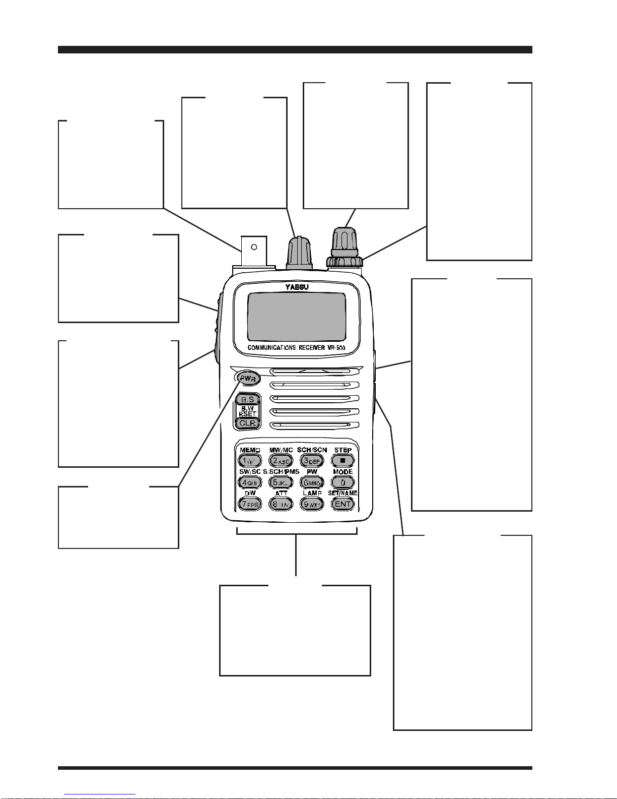
Controls & Connections ........................................ 2
Display Icons & Indicators ................................... 3
Keypad Functions .................................................. 4
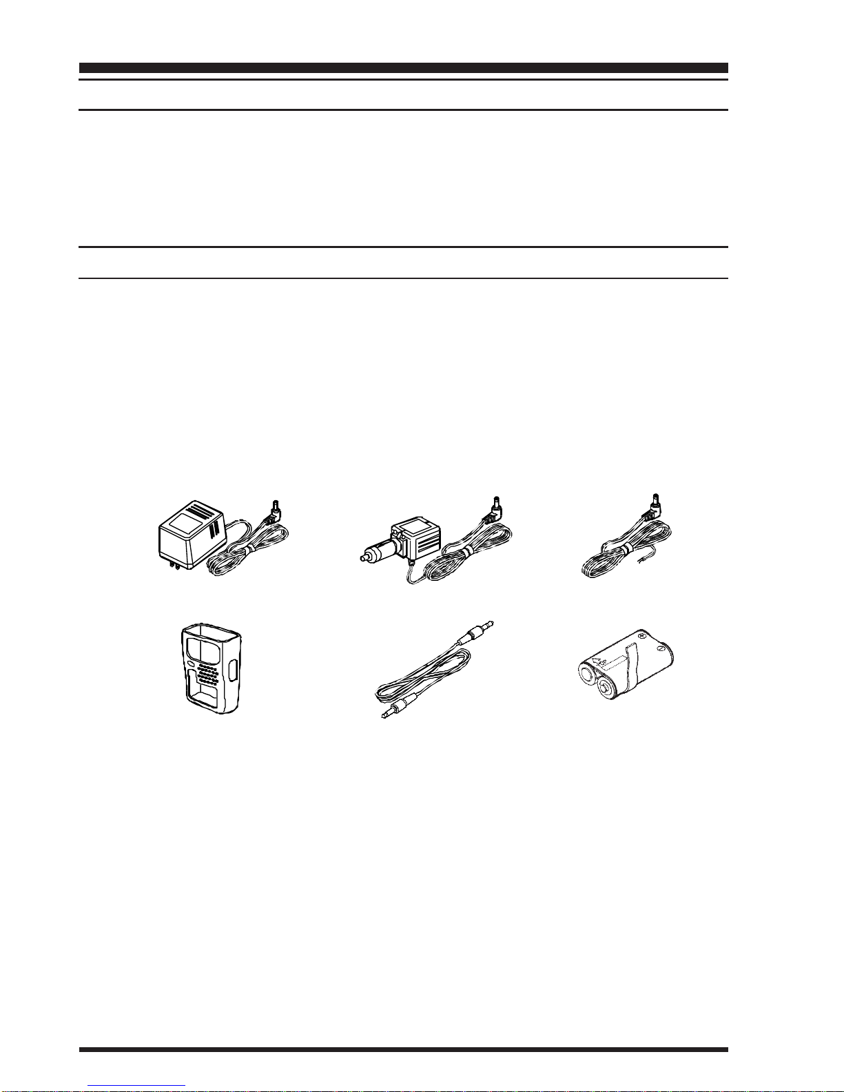
Accessories & Options ........................................... 6
Installation of Accessories ..................................... 7
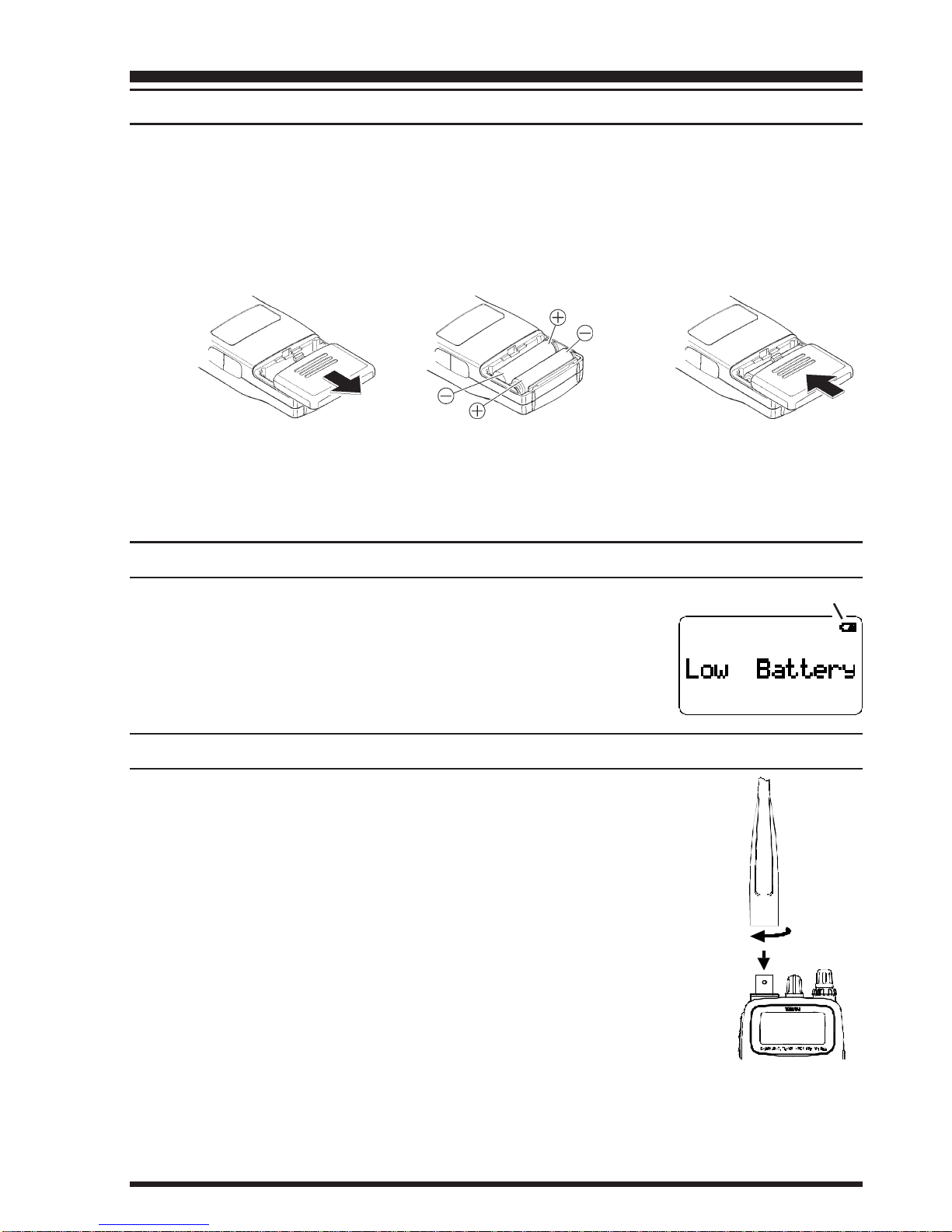
Battery Installation ............................................... 7
Low Battery Indication ......................................... 7
Antenna Installation ............................................. 7
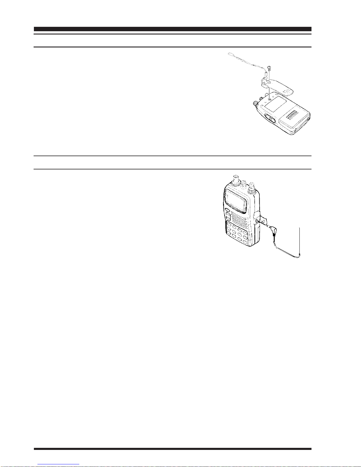
Belt Clip Installation ............................................ 8
AC Operation using the
optional NC-60 AC Adapter ............................ 8
Basic Operation...................................................... 9
Turning the Power On/Off ................................... 9
Adjusting the Volume and Squelch ...................... 9
RF Squelch System Setup .................................... 9
Mode Selection .................................................... 9
Frequency Navigation ......................................... 10
Tuning DIAL ..................................................... 10
Direct Keypad Frequency Entry ......................... 10
VFO Search ....................................................... 11
Changing the Direction of VFO
Search Scanning ....................................... 11
How to Skip (Omit) a Frequency
During VFO Search .................................. 12
Pre-Programmable Frequency Search ............ 13
Changing the Channel Steps .............................. 15
Preset Mode ....................................................... 16
Memory Mode...................................................... 17
Memory Storage................................................. 17
Simple Storage ............................................... 17
Designated Memory Storage .......................... 18
Memory Recall................................................... 19
Labeling Memories ............................................ 20
Memory Channel Scan ....................................... 21
Preferential Memory Scan (PMS) .................. 21
Memory Bank Scanning................................. 22
Mode Scan ..................................................... 23
Deleting Memory Channels................................ 23
Alpha-Numeric Memory Recall ......................... 24
Memory Channel Copying ................................. 25
Memory Channel Swap ...................................... 25
Memory Bank Copy ........................................... 26
Memory Bank Swap ........................................... 26
Clearing of a Memory Bank ............................... 27
Memory Channel Check..................................... 27
Band Scope ........................................................... 28
To Activate the Band Scope ............................... 29
Dual Watch........................................................... 30
Priority Monitoring ............................................. 32
Smart Search ................................................... 33
Reset .................................................................. 35
System Reset ...................................................... 35
Function/Menu Reset ......................................... 35
Set Mode ............................................................... 36
Specifications........................................................ 43
TM

VR-500 OPERATING MANUAL 1
Introduction
The VR-500 is a high-performance miniature com-
munications receiver providing general coverage
reception from 100 kHz to 1300 MHz on the CW,
SSB (LSB and USB), AM, and FM (Wide and
Narrow bandwidths) modes (this coverage includes
the AM and FM broadcast bands, HF Short-wave
Bands up to 16 MHz, VHF and UHF TV bands,
the VHF AM aircraft band, and a wide range of
commercial and public safety frequencies!) .
The VR-500's small size allows you to take it any-
where - hiking, skiing, or while walking around
town, and its operating flexibility brings the user
many avenues of operating enjoyment.
Operation of the VR-500 can be greatly simplified
by utilizing the “PRESET” mode. The “PRESET”
mode provides ten "starting point" frequencies (one
frequency in each of ten popular listening bands),
from which you may then begin manual tuning.
We appreciate your purchase of the VR-500, and
encourage you to read this manual thoroughly, so
as to learn about the many exciting features of your
exciting new Yaesu communications receiver!

VR-500 OPERATING MANUAL2
Controls & Connections
ANTENNAJack
Connect the sup-
pliedrubberflexan-
tenna (or another
antennapresenting
a 50Ωimpedance)
here.
EXT DC Jack
This coaxial DC jack al-
lows connection to an
external DC power
source (9~16 Volts DC).
The center pin of this jack
is the Positive (+) line.
Note: The protective
rubber cover over this
jack must be pulled up to
access it. Press it back
over the jack when not in
use, to protect the inside
of the radio from dust
and water.
[FUNC] Key
Press and hold in this
key, while pressing
one of the keypad's
buttons, to activate
the “Secondary” key
mode.
[MONI(LOCK)] Key
Press this key mo-
mentarily to “open”
the squelch manually,
allowing you to listen
for very weak signals.
Press this key
while
pressing the
[FUNC]
key
to activate the
“Key Lock” Feature.
[PWR] Key
Press and hold in this
key for two seconds
to toggle the radio's
power on and off.
KEYPAD
These 14 keys select many
of the most important oper-
ating features on the VR-
500. The functions of the
keys are described in detail
on pages 4 and 5.
DIAL Knob
This 20-position
detented rotary
switch is the main
tuningdial for the ra-
dio. It used for most
tuning, memory se-
lection, and func-
tion-setting tasks on
the radio.
VOL Knob
This control adjusts
the receiver's audio
volume level, and
also the keypad's
Beeper level.
Clockwise rotation
increases the audio
volume level.
SQL Knob
This control sets
the threshold level
at which received
signals (or noise)
openthe“Squelch.”
It should be ad-
vanced clockwise
just to the point
where background
noise is silenced,
so as to provide the
best sensitivity to
weak signals.
SP Jack
This 2-conductor, 3.5-
mm miniature phone
jack provides audio
output for an ear-
phone. The internal
loudspeaker is dis-
abled when this jack
is used.
Note: The protective
rubber cover over this
jackmust be pulledup
to access it. Press it
back over the jack
when not in use, to
protect the inside of
the radio from dust
and water.

VR-500 OPERATING MANUAL 3
Display Icons & Indicators
VFO Mode Activated
Memory Mode Activated
Memory Channel Scan Activated
VFO Search Activated
Dual Watch Activated
Priority Monitoring Activated
Memory Channel Number
S-Meter and Band Scope
Data Field
Operating Mode
Low Battery
ON and OFF Timer Activated
Battery Save Activated
Key Lock Activated
Scan Skip Memory Activated
Hold Scan and Search Activated
Busy Scan and Search Activated
Memory Channel Scan Activated
Preferential Scan List Activated
Mode Scan Activated
Attenuator Activated
Frequency

VR-500 OPERATING MANUAL4
Keypad Functions
Frequency Entry
Digit “3”
Start scanning.
Frequency Entry
Digit “6”
Frequency Entry
Digit “9”
Activate the Priority
Watch feature.
Display the operating
time and total transmit
time since you most
recently turned the
transceiver on.
Activate the back-
lighting lamp for the
display and keypad
keys for 5 seconds.
[3(SCH/SCN)]
[6(PW)]
[9(LAMP)]
Frequency Entry
Digit “1”
[1(MEMO)] [2(MW/MC)]
Frequency Entry
Digit “2”
Switch to the
“Memory” Mode.
None
Store the VFO
frequency into the
memory, or delete the
current memory
channel’s data.
[4(SW/SC)] [5(S.SCH/PMS)]
Press Key
Press [F/W]+
Press [F/W]+
Key for 2
seconds
[7(DW)] [8(ATT)]
Frequency Entry
Digit “4”Frequency Entry
Digit “5”
Frequency Entry
Digit “7”Frequency Entry
Digit “8”
Program and activate
Preferential Memory
ScanTM operaion.
Activate the Dual
Watch feature.
Store the VFO
frequency pair for the
Dual Watch feature
into the Dual Watch
Memory channel.
Engage the receiver
front-end attenuator.
Store the VFO fre-
quency into the “Scan
Skip” memory, or
delete the “Scan Skip”
memory channel data.
Program and activate
Smart SearCHTM
operation.
Press Key
Press Key
Press [F/W]+
Press [F/W]+
Press [F/W]+
Key for 2
seconds
Press [F/W]+
Key for 2
seconds
None None
None
None None

VR-500 OPERATING MANUAL 5
Keypad Functions
Input of the “Decimal
Point” frequency entry
digit (“ • ”).
Select the synthesizer
steps to be used
during VFO operation.
None
Frequency Entry
Digit “0”
Select the operating
(receiving) mode.
None
Enter the frequency
entry digit into the
VFO.
Activatethe “Set”(Menu)
mode,or enableprogram-
mingofthe Alpha/Numeric
nametag for thecurrent
memorychannel.
[ • (STEP)]
[0(MODE)]
[ENT(SET/NAME)]
[PTT]
[MON]
[LAMP]
Transmit.
Temporary High Power
Transmit.
Transmit.
Illuminate the LCD and
keypad for 5 seconds.
Illuminate the LCD and
keypad until you press
the key again.
Activate the Spectrum
Analyzer feature.
USA version:
Disable the Noise and
Tone Squelch.
European version:
Activate the T. CALL.
Reverse the transmit
and receive frequen-
cies while working
through a repeater.
None
Press Key
Press Key
Press [F/W]+
Press [F/W]+
Press [F/W]+
Press Key
[B.S(B.W)]
Activate the Band
Scope feature.
Select the Band Scope
sweep width.
[CLR(P.SET)]
[MONI(LOCK)]
Toggle the operating
mode between the
“
Preset Mode
” and the
“
Normal Mode
.”
None
Cancel the frequency
entry or Menu mode
setting.
“Open” the squelch
manually
Activate “Key Lock”
feature.
None Press [F/W]+
Key for 2
seconds
Press [F/W]+
Key for 2
seconds
Press [F/W]+
Key for 2
seconds
None
None

VR-500 OPERATING MANUAL6
Accessories & Options
ACCESSORIES SUPPLIED WITH THE VR-500
• Antenna
• Belt Clip
• Hand Strap
• Operating Manual
• Warranty Card
AVAILABLE OPTIONS FOR YOUR VR-500
•NC-60 AC Adapter
‚E-DC-5B DC Cable w/Noise Filter
ƒE-DC-6 DC Cable; plug and wire only
„CSC-72 Soft Case
…CT-35 Cloning Cable
†FNB-59 Rechargeable Battery Pack
•ƒ‚
„…
Availability of accessories may vary. Some accessories are supplied as standard per local
requirements, while others may be unavailable in some regions. Consult your Yaesu Dealer
for details regarding these and any newly-available options. Connection of any non-Yaesu-
approved accessory, should it cause damage, may void the Limited Warranty on this appa-
ratus.
†

VR-500 OPERATING MANUAL 7
Installation of Accessories
BATTERY INSTALLATION
rReferring to Figure 1, slide the Battery Cover toward the bottom to remove it.
rReferring to Figure 2, insert 2 fresh AA batteries into the Battery Holder. When in-
stalling batteries, insert the (–) end first, then press in the (+) end so the battery snaps
into place. Always replace two batteries at the same time.
rReplace the Battery Cover, as shown in Figure 3.
Note: If you do not use the VR-500 for a long time, remove the batteries from the radio,
as battery leakage could cause damage to the VR-500.
LOW BATTERY INDICATION
When the battery voltage becomes too low, the display will indi-
cate “Low Battery” and the “Battery” icon will appear, indicating
the batteries should be replaced. As battery voltage drops further,
the VR-500 will shut off.
ANTENNA INSTALLATION
rTo attach the supplied antenna to the VR-500, grasp the base of the
antenna firmly, and exert a moderate “pinching” pressure on the base
as you press the antenna onto the radio's antenna connector. While
exerting this pressure, rotate the antennaclockwise ¼ turn to lock the
antenna in place.
rTo remove the antenna from the VR-500, grasp the base of the an-
tenna firmly, and pinch the base of the antenna while rotating the
antennacounter-clockwise ¼ turn. You may now lift the antenna away
from the radio.
Figure 1 Figure 2 Figure 3
“Battery” Icon

VR-500 OPERATING MANUAL8
BELT CLIP INSTALLATION
To install the Belt Clip, first place the Hand Strap into the
hole at the top of the Belt Clip, then insert the mounting screw
through the belt clip, and affix it snugly to the mounting hole
on the back of the VR-500.
Do not install the supplied Belt Clip Mounting Screw if you
are not installing the Belt Clip! The screw will cause a “short
circuit” to the internal circuitry, causing serious damage!
Installations of Accessories
AC OPERATION USING THE OPTIONAL NC-60 AC ADAPTER
The VR-500 may be operated from your house current by
use of the optional NC-60AC Adapter.
To use the NC-60, turn the radio off, then plug the minia-
ture connector of the AC Adapter into the EXT DC jack on
the side of the radio. Now plug the AC Adapter into the
wall outlet. You may now turn on the radio.
If 12 Volt DC power is available, the optional E-DC-5B or
E-DC-6 DC Cable may be used for operation. When mak-
ing DC connections via the E-DC-5B or E-DC-6 DC Cable, be absolutely certain to ob-
serve the proper voltage level and polarity guidelines. Do not connect this radio directly to
a DC source which exceeds 15.0 Volts DC, nor to AC power of any kind.
NC-60
E-DC-5B
E-DC-6

VR-500 OPERATING MANUAL 9
TURNING THE POWER ON/OFF
•Press and hold the orange [PWR]Key for two seconds to turn the radio on or off.
‚When you turn on the radio, a “Welcome” message will appear on the display for two
seconds. After this interval, the frequency display will appear. Using the Menu system,
you can change the “Welcome” message yourself; see page 40 for details.
ADJUSTING THE VOLUME AND SQUELCH
•Rotate the VOL knob to adjust the receiver's audio volume. Clockwise rotation of the
VOL knob increases the volume level.
‚The VR-500's Squelch system allows you to mute the receiver's audio output when no
signals are being received. This reduces battery consumption, and reduces annoying
background noise.
ƒTo set the squelch, turn the SQL knob fully counter-clockwise, then turn it clockwise
just past the point where background noise is silenced. Do not rotate the SQL knob
much beyond this threshold point; if you do, the receiver will not respond to weak
signals.
RF SQUELCH SYSTEM SETUP
A special “RF Squelch” feature is provided on this radio. This feature allows you to set the
squelch so that only signals exceeding a user-defined signal level will open the squelch.
To set up the RF Squelch circuit for operation, use the following procedure:
•From the VFO mode, press the [ENT(SET)] key while pressing the [FUNC]key to
activate the “Set” (Menu) mode.
‚Rotate the DIAL knob to select Menu #19 “[RF Squelch].”
ƒRotate the DIALknob while pressing the [FUNC]key to se-
lect the desired signal strength level for the RF Squelch thresh-
old (1 ~ 9 or OFF).
„Press the [ENT(SET)] key while pressing the [FUNC]key to save your new setting
and exit to normal operation.
MODE SELECTION
The VR-500 automatically selects a default receiving mode according to the frequency
band on which you are operating. However, many bands (especially HF Shortwave) may
use a variety of transmission modes in a particular frequency segment.
If you want to change the receiving mode, press the [0(MODE)] key while pressing the
[FUNC]key. The receiving modes available are:
NFM èWFM èAM èLSBèUSB èCW èNFM • • •
Basic Operation

VR-500 OPERATING MANUAL10
FREQUENCY NAVIGATION
Tuning DIAL
Rotating the DIAL allows frequency tuning in the steps pre-programmed at the factory.
Clockwise rotation of theDIAL causes the radio to be tuned to toward ahigher frequency,
while counter-clockwise rotation will lower the operating frequency.
If you rotate the DIAL while pressing the [FUNC]key, the frequency will change in 1 kHz
steps (SSB/CW) or 1 MHz steps (AM/NFM/WFM). This feature is extremely useful for
making rapid frequency excursions over the wide tuning range of the radio. This step size
(1 MHz) can be changed; see the “Changing the Channel Steps” section on page 15 for
details.
Direct Keypad Frequency Entry
The desired operating frequency may be entered directly from the keypad.
To enter a frequency from the keypad:
•Enter the “MHz” portion of the frequency on which you wish to operate.
‚Enter the decimal point after the “MHz” portion by pressing the [• (STEP)] key.
ƒEnter four more digits to complete the frequency.
„If there are “zeroes” at the end of the frequency, you may press the [ENT (SET/NAME)]
key after the final non-zero digit.
Examples:
To enter 146.5200 MHz: Press [1] è[4] è[6] è[•] è[5] è[2] è[0] è[0].
To enter 810 kHz: Press [•] è[8] è[1] è[0] è[0].
To enter 445.4000 MHz: Press [4] è[4] è[5] è[•] è[4] è[ENT].
Basic Operation

VR-500 OPERATING MANUAL 11
Basic Operation
VFO SEARCH
The VFO Search feature causes the radio to scan the band, looking for active frequencies.
Before initiating a VFO Search, set the Squelch so that background noise is silenced. If
you are hearing background noise, the VFO Search feature will not initiate scanning.
From the VFO mode, press the [3(SCH/SCN)] key while press-
ing the [FUNC]key. The radio will initiate a VFO Search, tuning
toward a higherfrequency, and will stop when it receives a signal
strong enough to break through the Squelch threshold. The radio
will then hold on that frequency according to the setup of the “RESUME” mode.
To verify and/or modify the “RESUME” mode, again press the [3(SCH/SCN)] key while
pressing the [FUNC]key. The current “RESUME” mode is indicated at the top of the
Display (except for “Pause,” which is the default setting).
The following “RESUME” modes are available:
Pause èBusyèHold èPause è• • •
Pause (Default): In this mode, the VFO search will halt on a signal it encounters, and will
hold there for 5 seconds. If you do not take action to disable the VFO
search within that time period, the VFO search will resume even if the
station is still active.
Busy: In this mode, the VFO search will halt on a signal it encounters. Two sec-
onds after the carrier has dropped because the other station(s) ceased trans-
mission, the VFO search will resume. In this mode, the “BS” (BusySearch)
icon will appear at the top of the display.
Hold: In this mode, the VFO search will halt on a signal it encounters. It will not
restart unless you re-initiate a VFO search. In this mode, the “HS” (Hold
Search) icon will appear at the top of the display.
To stop the VFO search manually, just rotate the DIALone click.
Changing the Direction of VFO Search Scanning
If you wish to reverse the direction of the scan (i.e. toward a lower frequency, instead of a
higher frequency), rotate the DIAL one click to stop the VFO search, then rotate the DIAL
one click in the counter-clockwise direction. The VFO search direction will be reversed.
Note: If VFO Search has “paused” on a busy channel, it is only necessary to rotate the
DIAL one click in the counter-clockwise direction.
To revert to VFO search toward a higher frequency once more, rotate the DIAL one click,
then rotate it one click clockwise. If paused on a busy channel, just rotate the DIAL one
click clockwise.
Press the [CLR(P.SET)] key to cancel the VFO search.

VR-500 OPERATING MANUAL12
How to Skip (Omit) a Frequency During VFO Search
If the VFO search stops on a frequency or frequencies that you do not need (such as a
spurious radiation from a television), such frequencies can be “skipped” during VFO Search
scanning. This is accomplished by storing these frequencies in a special “Frequency Skip
Memory Bank” reserved for this purpose.
To skip a frequency during VFO Search scanning:
•While VFO Search is stopped on the frequency that you do
not need, press the [4(SW/SC)] key while pressing the
[FUNC]key. The display will indicate “S
nn
WRITE?” as a
request for command confirmation (see next step).
‚Now, press the [4(SW/SC)] key while pressing the [FUNC]key again, to store the
frequency into the VFO Frequency Skip Memory (VFO Frequency Skip Memory
Write), it is to be ignored during VFO search.
Note that the VR-500 has 100 VFO Frequency Skip Memory Channels (channel num-
ber “S00 ~ S99”).
To re-institute the frequency into the VFO search loop:
•Press and hold in the [FUNC]key, then press the[1(MEMO)] key, repeatedly if neces-
sary, to recall the VFO Frequency Skip Memory mode (“S
nn
” will appear at the left
side of the display).
‚Rotate the DIAL knob to select the channel to be re-instituted.
ƒPress the [4(SW/SC)] key while pressing the [FUNC]key.
The display will indicate “S
nn
CLEAR?” as a request for
command confirmation (see next step).
„Now, press the [4(SW/SC)] key while pressing the [FUNC]
key again; this action will delete the channel from the VFO Frequency Skip Memory,
so as to re-institute the frequency into the VFO Search scanning loop.
Basic Operation

VR-500 OPERATING MANUAL 13
Pre-Programmable Frequency Search
The VR-500 allows you to program up to ten band segments within which VFO Search
scanning can be limited. This allows your radio's search to be concentrated on the most
active band segments in your local area, without wasting time in unused frequency segments.
To confine your search within one of the pre-programmed segments, you must first set
Menu #12 (“[Search Mode]”) to the “LIMIT” option, per the following procedure:
•Press and hold in the[FUNC]key; while holding it in, press the [ENT(SET/NAME)]
key to activate the “Set” (Menu) mode.
‚Rotate the DIALknob to select Menu #12 [Search Mode].
ƒPress and hold in the [FUNC]key; while holding it in, rotate
the DIAL knob to select “LIMIT” as the VFO Search mode.
„Press the [CLR(P.SET)] key to exit to the VFO mode.
The VR-500 has been pre-programmed at the factory with default band limits. These are
grouped as “Search Band Memories” per the list below.
Basic Operation
Here is the procedure for initiating VFO Search Scanning within one of the above bands:
•Press and hold in the [FUNC]key; while holding it in, press the [3(SCH/SCN)] key;
the radio will begin VFO Search Scanning (at this point, the frequency range is unim-
portant).
‚While VFO Search is active, press (momentarily) the key corresponding with theSearch
Band Memory as shown above. The VFO Search will now shift to the band segment
within the Pre-Programmed Frequency Range associated with that memory number.
For example, if you press[7]after initiating VFO Search Scan-
ning, the search will be limited to the frequency range 144.0-
148.0 MHz. While VFO Search Scanning is in progress, you
may change ranges by just pressing one of the numbered keys
momentarily; the radio will jump to that range instantaneously, and will immediately
begin VFO Search Scanning inside the new range.
ƒOther aspects of the VFO Search feature within the pre-programmed band limits, such
as the “Resume” mode, are the same as during “regular” VFO Search Scanning.
„Press the [CLR[P.SET)] key to halt the search and return to manual tuning via the
DIAL knob.
Pre-Programmed
Frequency Range 50.0000~ 54.0000 MHz
88.0000~ 108.0000 MHz
144.0000~ 148.0000 MHz
430.0000~ 450.0000 MHz
1240.0000~1300.0000 MHz
0.5200 ~ 1.8000 MHz
1.8000 ~ 3.6000 MHz
3.6000 ~ 10.5000 MHz
10.500 ~ 21.0000 MHz
21.0000~ 30.0000 MHz
0
1
2
3
4
Search Band
Memory # 5
6
7
8
9
Search Band
Memory # Pre-Programmed Frequency
Range

VR-500 OPERATING MANUAL14
You can customize the Pre-Programmed Frequency Range for any of the bands shown on
the previous page, so as to allow you to scan just the band segments you want.
To program the Pre-Programmed Frequency Ranges :
•Select the Lower Frequency Limit for the Pre-Programmed Frequency Range using
direct keypad frequency entry or the main tuning DIAL.
‚Press and hold in the [FUNC]key; while holding it in, press the [3(SCH/SCN)] key
for 2 seconds. The display will indicate “SCH A Write!” briefly, then the frequency
display will return.
ƒNext, select the Higher Frequency Limit for the Pre-Programmed Frequency range.
„Press and hold in the [FUNC]key; while holding it in, press the [3(SCH/SCN)] key
for 2 seconds. The display will indicate “SCH B Write!”
…Now press the [3(SCH/SCN)] key momentarily while pressing the [FUNC]key. This
activates the VFO Search Scanning mode.
†Finally, press and hold in (for 2 seconds) in the numbered key of the Search Band
Memory into which you wish to store these band limits.
Example: Store the band limits 9.450 MHz and 9.850 MHz into Search Band
Memory #2.
•Select 9.450 MHz as the Lower Frequency Limit using direct keypad frequency
entry. Press [9]è[•]è[4]è[5]è[ENT(SET/NAME)].
‚Press and hold in the [FUNC]key; while holding it in, press the [3(SCH/SCN)]
key for 2 seconds. The display will indicate “SCH A Write!” briefly, then the
frequency display will return.
ƒNext, select 9.850 MHz as the Higher Frequency Limit.
„Press [9]è[•]è[8]è[5]è[ENT(SET/NAME)].
…Press and hold in the [FUNC]key; while holding it in, press the [3(SCH/SCN)]
key for 2 seconds. The display will indicate “SCH B Write!”
†Now press the [3(SCH/SCN)] key momentarily while pressing the [FUNC]
key. This activates the VFO Search Scanning mode.
‡Finally, press and hold in the [2(MW/MC)] key for 2 seconds.
Basic Operation

VR-500 OPERATING MANUAL 15
You can check the frequency ranges of the Search Band Memories quickly, to see if you
want to re-program other ranges. To do this:
•From the VFO mode, press the [ENT(SET)] key while pressing the [FUNC]key to
activate the “Set” (Menu) mode.
‚Rotate the DIAL knob to select Menu #13 [SRCH Memory].
ƒRotate the DIAL knob while pressing the [FUNC]key to re-
view the programming of the Search Band Memories. The
Search BandNumber (0 ~ 9) will appear at the left side of the
display, while the current frequency range for that Search Band
Memory will appear at the right side of the display.
„Press the[ENT(SET)] key while pressing the [FUNC]key to exit to normal operation.
CHANGING THE CHANNEL STEPS
This radio's synthesizer provides the option of utilizing channel steps of 0.05/0.1/1/5/6.25/
9/10/12.5/15/20/25/30/50/100 kHz per step, as well as an automatic step selection based
on the current listening frequency (“AUTO”). Additionally, the digit of the frequency to be
changed during “Fast” tuning may be selected, so as to allow rapid frequency excursions at
the rate you prefer.
To change the channel steps:
•Press the [• (STEP)] key (momentarily) while pressing the
[FUNC]key.
‚Rotate the DIAL knob to select the desired frequency step
side for normal tuning via the DIAL knob.
ƒIf you want to change the frequency digit which changes dur-
ing “Fast” tuning, press and hold in the [FUNC]key; while holding it in, rotate the
DIAL knob to select the “blinking” digit to be changed during fast tuning.*
„Press the [• (STEP)] key while pressing the [FUNC]key to save the new setting and
exit to normal operation.
* To verify the new “Fast” step setting, complete the above procedure.
Now press and hold in the [FUNC]key; while holding it in, rotate the DIAL
knob;
the digit selected in step ƒabove will change with each click of the DIAL knob.
Basic Operation
[FUNC]+DIAL Step
DIAL Step

VR-500 OPERATING MANUAL16
PRESET MODE
Operation of the VR-500 can be greatly simplified by utilizing the “PRESET” mode. The
PRESET mode provides ten “starting point” frequencies (one frequency in each of ten
popular listening bands), from which you may then begin manual tuning.
To operate in the PRESET mode:
•Press the [CLR(P.SET)] key (momentarily) while pressing the [FUNC]key to change
the VR-500 operating mode to PRESET.
‚Now just press one of the numbered keys on the keypad to recall the Pre-Programmed
Frequency corresponding to that key, as shown below.
Basic Operation
1
2
3
4
5
6
7
8
9
•
0
0.5200 MHz (AM)
3.5000 MHz (LSB)
7.0000 MHz (LSB)
14.0000 MHz (USB)
50.0000 MHz (CW)
88.0000 MHz (WFM)
144.0000 MHz (CW)
430.0000 MHz (NFM)
1240.0000 MHz (NFM)
Weather Channel
This is a special “PRESET” key which toggles
through the Pre-Programmed Frequencies,
per the following selections:
Channel
Number Pre-Programmable Frequency
ƒOnce you have chosen a PRESET band segment, you can move off of the Pre-Pro-
grammed Frequency by rotating the DIAL knob. However, you cannot perform direct
frequency entry, as each keystroke will select a new Pre-Programmed band segment.
„Press the [CLR(P.SET)]key again, while pressing the [FUNC]key, to disable the
PRESET mode and return to normal operation.

VR-500 OPERATING MANUAL 17
Memory Mode
The VR-500 provides 1000 “standard” memory channels, numbered “000” through “999.”
Memory channels may be used to store frequencies of particular interest, for convenient
recall without the need to scan through an entire operating band.
These memories are partitioned into ten Memory Banks, each
holding up to 100 memory channels. The Memory Bank number
is the first digit of the Memory Channel number, so Memory Chan-
nel005 is in Memory bank “0,” while Memory Channel425 is in
Memory Bank “4.”
MEMORY STORAGE
Two forms of memory storage are available on the VR-500:
• “Simple” memory storage automatically memorizes the desired frequency into the
next-available unused memory channel register (without regard to any particular
memory channel number).
• “Designated” memory storage allows you to assign the frequency data to any desired
memory channel number.
Simple Storage
•While operating in the VFO mode, select the desired frequency and reception mode
(AM, NFM, etc.) for the station to be memorized.
‚Press and hold in the[FUNC]key, then press the [2(MW/MC)]
key momentarily. The microprocessor will automatically se-
lect the next-available “open” memory channel (a memory reg-
ister on which no data has been stored). On the left side of the
display, a three-digit number will appear, indicating the chan-
nel number which will be used for channel data storage. On the right side, “MW/NAME?”
will appear (“MW” stands for “Memory Write”).
ƒIf you wish to append an alpha-numeric label (name) to the channel, press and hold in
the [FUNC]key, then press the [ENT(SET/NAME)] key. Now skip to step ƒof the
Labeling Memories section below, and perform steps ƒthrough ‡.
„Now, press the [2(MW/MC)] key once more while still holding in the [FUNC]key.
This stores the frequency into the memory. “WRITE!” will appear on the right side of
the display, to confirm that the frequency data was successfully stored.
Note: You must press the [2(MW/MC)] key per this step whether or not you are ap-
pending an alpha-numeric label to a memory.
Memory Bank “4”
Memory Channel “425”
“Open” Memory Channel

VR-500 OPERATING MANUAL18
Designated Memory Storage
If you wish to store the frequency into a particular memory channel number, use the “Des-
ignated Memory” storage procedure:
•While operating in the VFO mode, select the desired frequency and reception mode
(AM, NFM, etc.) for the station to be memorized.
‚Press the [2(MW/MC)] key while pressing the [FUNC]key.
ƒIf you wish to append an alpha-numeric label (name) to the channel, press and hold in
the [FUNC]key, then press the [ENT(SET/NAME)] key. Now skip to step ƒof the
Labeling Memories section on page 20, and perform steps ƒthrough ‡.
„Now enter the three-digit memory channel number to be “stored” from the keypad.
When you touch the third digit of the memory channel number, “Write!” will appear at
the right side of the display, confirming that the frequency data has been stored into the
designated memory channel.
Example: Store 162.550 MHz into Memory Channel 005:
•Use the keyboard to enter the desired frequency.
Press [1]è[6]è[2]è[•]è[5]è[5]è[ENT(SET/NAME)].
‚Press the [FUNC]key, then press [2(MW/MC)]. A channel number will appear at
the left side of the display, and “MW/Name?” will appear at the right side.
ƒNow press [0]è[0]è[5]. The display will indicate “005 Write!” momentarily,
after which the display will revert to 162.550 MHz, which is the current VFO
frequency. Memory storage into channel #005 is now complete.
Example: Store 162.450 MHz into Memory Channel 010, and append the label "NOAA
450” to the channel data:
Use the keyboard to enter the desired frequency.
Press [1]è[6]è[2]è[•]è[4]è[5]è[ENT(SET/NAME)].
Press the [FUNC]key, then press [2(MW/MC)]. A channel number will appear at
the left side of the display, and “MW/Name?” will appear at the right side.
Press the [FUNC]key, then press [ENT(SET/NAME)]. You may now release the
[FUNC]key.
You will observe a space blinking on the LCD; this indicates that you are in the
alpha-numeric label entry mode.
Press [6 MNO]è[6 MNO]to enter “N” as the first character. Now press the
[FUNC]key; while holding it in, rotate the DIAL one click clockwise to move on
to the next digit.
Press [6 MNO]è[6 MNO]è[6 MNO]to enter “O” as the next character.
Rotate theDIAL one click clockwise while holding in the [FUNC]key to move on
to the next character.
Memory Mode
Other manuals for VR-500
2
Table of contents
Other Yaesu Receiver manuals

Yaesu
Yaesu FRG-8800 User manual

Yaesu
Yaesu VR-5000 User manual

Yaesu
Yaesu VR-500 User manual

Yaesu
Yaesu VR-5000 User manual

Yaesu
Yaesu FT-560 User manual

Yaesu
Yaesu FRG-9600 User manual

Yaesu
Yaesu FRG-100 User manual

Yaesu
Yaesu FR-100-b User manual

Yaesu
Yaesu FRG-7000 User manual

Yaesu
Yaesu VR-120 User manual