INSTALLATION
The FT-227RB transceiver is designed primarily
for mobile service, requiring only an antenna and
13.8 volt DC power source for operation. The
transceiver has been pre-tuned at the factory, and
requires no further adjustment for normal oper-
ation into a 50 ohm load.
Under no circumstances should the power cable
ever be connected to AC power. OUR WAR-
RANTY DOES NOT COVER DAMAGE CAUSED
BY APPLICATION OF AC POWER TO THE
POWER JACK ON THE REAR APRON OF THE
TRANSCEIVER.
ANTENNA CONSIDERATIONS
In antenna installations, it is desirable that the
antenna be located as high and in the clear as
possible. In addition, be certain that the SWR on
the feedline is less than 1.5 : 1. A higher SWR may
cause a reduction in power output, because of the
protective circuitry incorporated in design. As well,
high SWR will increase the feedline losses.
In all installations, do not economize on coaxial
cable. For mobile applications, in which the feed-
line length is 20 feet or less, type RG-58A/U cable
is satisfactory, and the foam types are preferred,
because of their lower loss. For base station
systems, type RG8A/U may be used for moderate
lengths; for very long cable installations, we recom-
mend the use of type RG-17A/U, air-dielectric
"heliax" cable, or aluminum-jacketed "foamflex"
coax. Beware of "bargain" coax, as the shield
coverage may be very poor, and this can seriously
degrade system performance.
BASE STATION INSTALLATION
As base station, the FT-227RB requires a power
source of 13.8 volts DC at 2.5 amperes. A base
station stand is included with your transceiver,
for easy viewing.
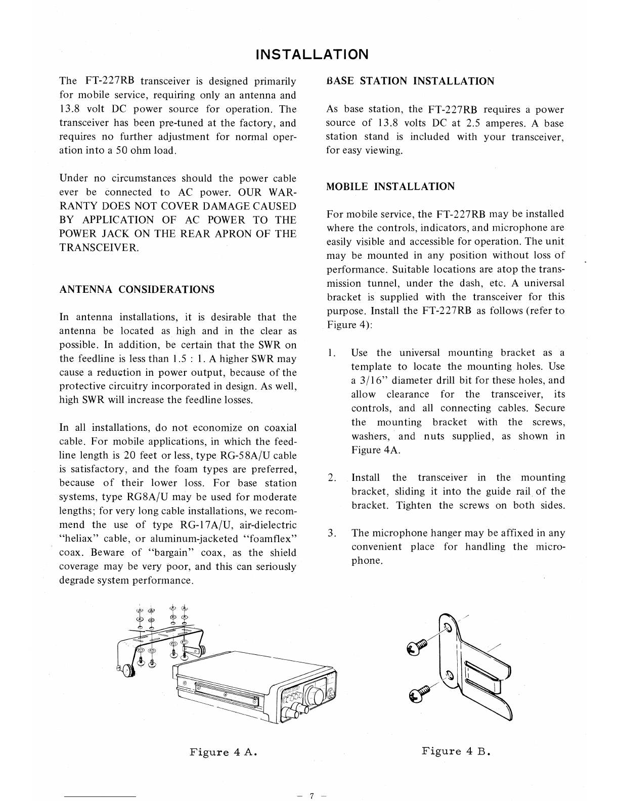
MOBILE INSTALLATION
For mobile service, the FT-227RB may be installed
where the controls, indicators, and microphone are
easily visible and accessible for operation. The unit
may be mounted in any position without loss of
performance. Suitable locations are atop the trans-
mission tunnel, under the dash, etc. A universal
bracket is supplied with the transceiver for this
purpose. Install the FT-227RB as follows (refer to
Figure 4):
Use the universal mounting bracket as a
template to locate the mounting holes. Use
a 3/16" diameter drill bit for these holes, and
allow clearance for the transceiver, its
controls, and all connecting cables. Secure
the mounting bracket with the screws,
washers, and nuts supplied, as shown in
Figure 4A.
2.
Install the transceiver in the mounting
bracket, sliding it into the guide rail of the
bracket. Tighten the screws on both sides.
3.
The microphone hanger may be affixed in any
convenient place for handling the micro-
phone.
Figure 4 A.
Figure 4 B.