Yaesu FT-252 User manual

VHF FM TRANSCEIVER
FT-252
Operating Manual
YAESU MUSEN CO., LTD.
Tennozu Parkside Building
2-5-8 Higashi-Shinagawa, Shinagawa-ku, Tokyo 140-0002 Japan
YAESU USA
6125 Phyllis Drive, Cypress, CA 90630, U.S.A.
YAESU UK
Unit 12, Sun Valley Business Park, Winnall Close
Winchester, Hampshire, SO23 0LB, U.K.
YAESU HK
Unit 2002, 20/F, 9 Chong Yip Street,
Kwun Tong, Kowloon, Hong Kong
cover_130313.indd 1 2013/03/13 17:32:04

Contents
Scanning............................................................29
VFO Scanning ...............................................30
Manual VFO Scan .....................................30
Programmed VFO Scan.............................30
Memory Scanning..........................................31
How to Skip (Omit) a Channel
during Memory Scan Operation ................31
Preferential Memory Scan.........................32
Memory Bank Scan ...................................33
Programmable (Band Limit) Memory Scan
(PMS).............................................................34
“Priority Channel” Scanning
(Dual Watch)..................................................35
Automatic Lamp Illumination
on Scan Stop ..................................................37
Band Edge Beeper .........................................37
Weather Alert Scan ........................................38
Emergency Channel Operation ......................39
Smart Search Operation..................................40
ATS
(Automatic Transponder System)
.....................41
DTMF Operation .............................................43
Miscellaneous Settings.....................................46
CW Identier Setup .......................................46
Password........................................................47
Changing the Channel Steps..........................48
Receive Battery Saver Setup .........................48
TX Battery Saver ...........................................49
Transmitter Time-Out Timer (TOT) ..............49
Busy Channel Lock-Out (BCLO)..................50
DCS Code Inversion......................................50
Changing the TX Deviation Level.................51
Reset Procedures ..............................................52
Set Mode ...........................................................53
Specications ....................................................63
General Description ...........................................1
Accessories & Options .......................................2
Controls & Connections ....................................3
Top & Front Panel ...........................................3
LCD .................................................................4
Installation of Accessories .................................5
Antenna Installation.........................................5
Installation of FNB-124LI Battery Pack..........5
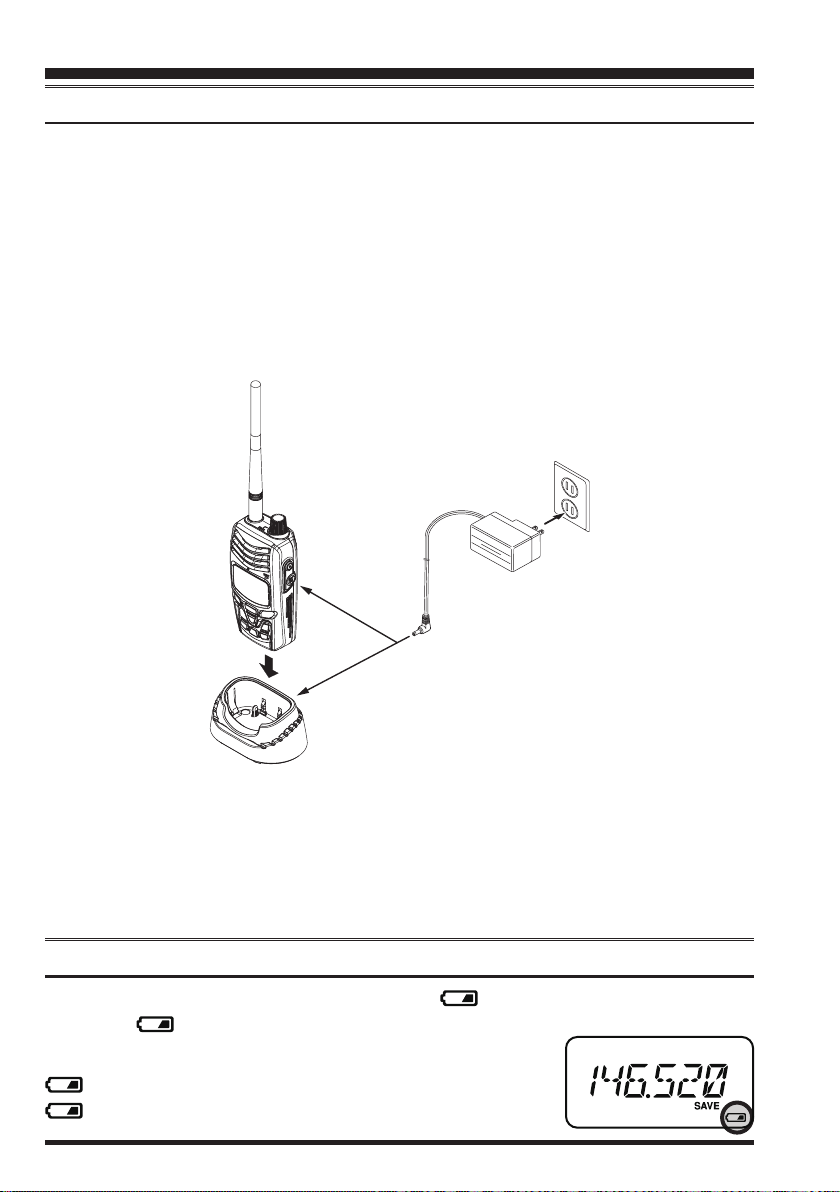
Battery Charging..............................................6
Low Battery Indication....................................6
Belt Clip Installation / Removal ......................7
Operation............................................................8
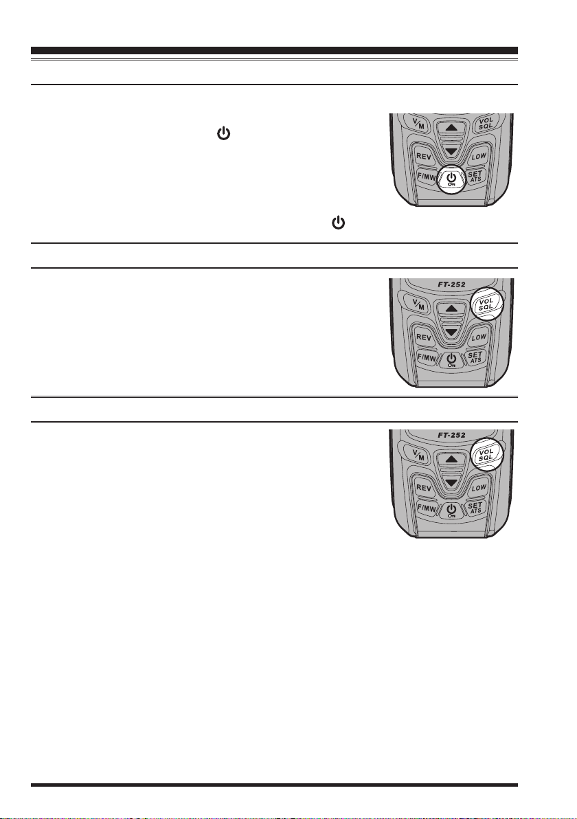
Switching Power On and Off...........................8
Adjusting the Audio Volume Level .................8
Squelch Adjustment.........................................8
Frequency Navigation......................................9
Transmission..................................................10
Advanced Operation........................................11
Keyboard Locking .........................................11
LCD Illumination...........................................12
Disabling the Keypad Beeper ........................12
RF Squelch.....................................................13
Checking the Battery Voltage ........................13
Repeater Operation..........................................14
Repeater Shifts...............................................14
Automatic Repeater Shift (ARS)...................14
Manual Repeater Shift Activation .................15
CTCSS/DCS Operation...................................17
CTCSS Operation ..........................................17
DCS Operation...............................................18
CTCSS/DCS Bell Operation..........................19
Split Tone Operation......................................20
Tone Calling (1750 Hz) .................................21
Memory Mode ..................................................22
Memory Storage ............................................22
Storing Independent
Transmit Frequencies (“Odd Split”)..........22
Memory Recall ..............................................23
HOME Channel Memory ..............................23
Labeling Memories........................................24
Enable the Memory
Alpha-Numeric Tag display...........................24
Memory Offset Tuning ..................................25
Deleting Memories ........................................26
Memory Bank Operation ...............................26
Moving Memory Data to the VFO ................27
Memory Only Mode ......................................27
Weather Broadcast Channels .........................28
cover_130313.indd 2 2013/03/13 17:32:04

FT-252 OperaTing Manual 1
General Description
The FT-252 is a compact submersible*, high-performance FM hand-held providing up
to ve watts of RF power, and a wealth of convenient features for 2-meter amateur band
operations.
Additional features include a transmit Time-Out Timer (TOT), Automatic Power-Off
(APO), Automatic Repeater Shift (ARS), YAESU’s exclusive Auto Transponder System
(ATS), which “beeps” the user when moving out of communications range with another
ATS equipped station; and an RF squelch circuit which allows adjusting the squelch to
open at a programmed setting of the S-Meter, thus reducing guesswork in setting the
squelch threshold.
We appreciate your purchase of the FT-252, and encourage you to read this manual
Thoroughly. You will learn about the many exciting features of your exciting new YAE-
SU hand-held transceiver!
* IPX5 water submersible.
honbun_130313.indd 1 2013/03/13 19:47:31

FT-252 OperaTing Manual2
Supplied Accessories
FNB-124LI 7.4 V Rechargeable Lithium-Ion Battery Pack
YHA-75 Antenna
SAD-11B AC Wall Charger (for USA version)
PA-48B/C/FAC Wall Charger (for EXP version)
CLIP-24 Belt Clip
Operating Manual
Quick Manual
Warranty Card
Available Options
FNB-124LI 7.4 V Rechargeable Lithium-Ion Battery Pack
SAD-11B AC Wall Charger
PA-48B/C/FAC Wall Charger
CD-57 Charger Cradle
SDD-11 DC/DC Converter (with cigarette lighter plug)
E-DC-6 DC Cable (plug and wire only)
YHA-75 Antenna
CLIP-24 Belt Clip
CN-3 BNC-to-SMA Adapter
“B” sufx is for use with 100-120 VAC, “C” is for use with 230-240 VAC, and “F”
is for use with 220 VAC.
Availability of accessories may vary. Some accessories are supplied as standard per lo-
cal requirements, while others may be unavailable in some regions. This product is de-
signed to perform optimally when used with genuine YAESU accessories. YAESU shall
not be liable for any damage to this product and/or accidents such as re, leakage or
explosion of a battery pack, etc., caused by the malfunction of non- YAESU accessories.
Consult your YAESU dealer for details regarding these and any newly-available options.
Connection of any non-YAESU-approved accessory, should it cause damage, may void
the Limited Warranty on this apparatus.
Accessories & Options
honbun_130314.indd 2 2013/03/14 17:43:35

FT-252 OperaTing Manual 3
Antenna Jack
Connect the supplied rubber ex antenna (or an-
other antenna presenting a 50-Ohm impedance)
here.
DIAL Knob
The main tuning Dial is used to set the operating
frequency. It is also used for menu selections and
other adjustments.
Speaker
The internal speaker is located here.
PTT (Push To Talk) Switch
Press this switch to transmit, and release it (to receive) after your transmission is
completed.
LCD (Liquid Crystal Display)
The display shows the current operating conditions, as described on the next page.
Keypad
These 9 keys select many of most important operating features on the FT-252.
MIC
The internal microphone is
located here.
EXT DC Jack
This coaxial DC jack allows
connection to an external DC
power source (5-10V DC).
The center pin of this jack is
the Positive (+) connection.
Do not allow the FT-
252 to become sub-
merged in water while the
rubber cap over the EXT DC
jack is removed.
Controls & Connectors
honbun_130313.indd 3 2013/03/13 19:47:33

FT-252 OperaTing Manual4
Controls & Connectors (LCD)
Operating Frequency
BUSY Indicator
TX Indicator
Memory Channel Number
S- & PO Meter
Skip Memory Channel or Pref-
erential Memory Channel
Repeater Shift Direction
CTCSS/DSC Operation
Bell Alarm Active
Battery Saver Active
Dual Watch Active
Priority Channel
Battery Indicator
Memory Bank Active
Low TX Power Selected
Automatic Power-Off Active
DTMF Autodial Active
Secondary Keypad Active
honbun_130313.indd 4 2013/03/13 19:47:33

FT-252 OperaTing Manual 5
Antenna Installation
The supplied antenna provides good results over the entire frequency range of the trans-
ceiver. However, for enhanced reception on certain non-Amateur frequencies, you may
wish to connect an antenna designed specically for that fre-
quency range, as the supplied antenna is necessarily a com-
promise outside the Amateur band, and cannot be expected to
provide high performance at all frequencies.
To install the supplied antenna, hold the bottom end of the an-
tenna, then screw it onto the mating connector on the transceiv-
er until it is snug. Do not over-tighten by use of extreme force.
Notes:
Never transmit without having an antenna connected.
When installing the supplied antenna, never hold the upper part of the antenna while
screwing it onto the mating connector on the transceiver.
If using an external antenna for transmission, ensure that the SWR presented to the
transceiver is 1.5:1 or lower, to avoid excessive feedline loss.
Installation of FNB-124LI Battery Pack
The FNB-124LI is a high performance Li-ion battery providing high capacity in a compact
package. Recharging can be completed while the pack is installed inside the FT-252.
Installation of the battery is easy and quick:
Release the Battery Cover Latch and remove the
Battery Cover from the radio by lifting the top of the
Cover.
Connect the 3-pin plug from the Battery pack to the
battery jack on the transceiver.
Install the FNB-124LI Battery Pack into the radio.
Replace the Battery Cover by carefully aligning the
two tabs on the bottom of the cover with the slots
on the radio, then gently press the top side of the
Battery Cover. Conrm that a Rubber Gasket of the
Battery Cover is installed correctly.
Close the Battery Cover Latch until it locks in place
with a “Click”.
Caution:
To insure the FT-252 will not be damaged by water
intrusion, make sure the battery cover is properly
installed and the battery latch is closed.
Installation of Accessories
honbun_130313.indd 5 2013/03/13 19:47:35

FT-252 OperaTing Manual6
Battery Charging
If the battery has never been used, or its charge is depleted, it may be charged by con-
necting the SAD-11B or PA-48 AC Wall Charger, as shown in the illustration, to the
EXT DC jack. If only 12 ~ 14 Volt DC power is available, the optional SDD-11 DC/DC
Converter (with its cigarette lighter plug) or E-DC-6 DC Cable may also be used for
charging the battery.
The display will indicate “CHRG”, while the battery is being charged. When charging is
completed, the “CHRG” indication disappears from the display.
A fully-discharged pack will be charged completely in 5 hours. Disconnect the SAD-
11B or PA-48 from the EXT DC jack and the AC line outlet.
Installation of Accessories
Important Note
The
SAD-11B and PA-48 is not designed to power the transceiver for operation (re-
ception or transmission).
Please be advised that the SAD-11B and PA-48 may contribute noise to TV and ra-
dio reception in the immediate vicinity, so we do not recommend its use adjacent to
such devices.
Low Battery Indication
When the battery charge is almost depleted, a “ ” icon will appear on the display.
When the “ ” icon appears, it is recommended that you charge the battery soon.
No Icon: Sufcient Operating Battery Power
: Lower Battery Power
(Blinking): Prepare to charge (or replace) the Battery
CD-57
(option)
honbun_130314.indd 6 2013/03/14 17:44:39

FT-252 OperaTing Manual 7
Belt Clip Installation / Removal
Installation of Accessories
To install the Belt Clip:
Align the Belt Clip to the groove
above the Battery compartment, then
press the Belt Clip downward until it
locks in place with a “Click”.
To remove the Belt Clip:
Press the Belt Clip tab away from the
transceiver to unlock the Belt Clip,
then slide the Belt Clip up-ward to re-
move it.
Belt Clip Tab
honbun_130313.indd 7 2013/03/13 19:47:38

FT-252 OperaTing Manual8
Switching Power ON and OFF
Be sure the Battery Pack is installed, and the battery is fully charged. Connect the
antenna to the top panel ANTENNA jack.
Press and hold the [POWER()] key for two seconds to
turn the radio on. The current DC supply voltage will be
indicated on the display for 2 seconds. After this 2 second
interval, the display will resume its normal indication of
the operating frequency.
To turn the radio off, press and hold the [POWER()] key for two seconds.
Adjusting the Audio Volume Level
Press the [VOL/SQL] key to enter the receiver audio adjust-
ment mode. When “VOL” is displayed, rotate the DIAL knob
or press the [p]/[q] key until the noise or audio from the
speaker is at a comfortable level.
Squelch Adjustment
Press the [VOL/SQL] key twice to enter the squelch level ad-
justment mode. When “SQL” is displayed, rotate the DIAL
knob or press the [p]/[q] key to set the Squelch so that the
background noise is just silenced. This state is known as the
“Squelch Threshold”.
1) A special “RF Squelch” feature is provided on this ra-
dio. This feature allows you to set the squelch so that only signals exceeding a cer-
tain S-meter level will open the squelch. See page 13 for details.
2) If you’re operating in an area of high RF interference, you may need to con-
sider “Tone Squelch” operation using the built-in CTCSS Decoder. This feature
will keep your radio quiet until a call is received from a station sending a carrier
which contains a matching (subaudible) CTCSS tone. If your friends have radios
equipped with DCS (Digital Coded Squelch) like your FT-252, you may try using
that mode for silent monitoring of busy channels.
Operation
honbun_130313.indd 8 2013/03/13 19:47:39

FT-252 OperaTing Manual 9
Operation
Frequency Navigation
The FT-252 will initially be operating in the “VFO” mode, a channelized system which
allows free tuning throughout the operating band.
Two basic frequency navigation methods are available on the FT-252:
1)Tuning Dial
Rotation of the DIAL allows tuning in the pre-programmed steps established for the op-
erating band. Clockwise rotation of the DIAL causes the FT-252 to be tuned upward in
frequency, while counter-clockwise rotation will lower the operating frequency.
If you press the [F/MW] key momentarily, then rotate the DIAL, frequency steps of 1
MHz will be selected. This feature is extremely useful for moving rapidly over the wide
tuning range of the FT-252.
2)Scanning
Press and hold in either the [p]or [q] key for one second to initiate upward or down-
ward scanning (Manual VFO Scan).
If you wish to reverse the direction of the scan (i.e. toward a lower frequency, instead
of a higher frequency), just rotate the DIAL one click in the counter-clockwise direc-
tion while the FT-252 is scanning. The scanning direction will be reversed. To revert to
scanning toward a higher frequency once more, rotate the DIAL one click clockwise.
The scanner will stop when it receives a signal strong enough to break through the
Squelch threshold. The FT-252 will then hold on that frequency according to the setting
of the “RESUME” mode (Set Mode Item 29: RESUME). Press the PTT switch momen-
tarily to cancel the scanning. This only stops the scan; it does not cause transmission to
occur. See page 29 for details regarding Scan Operation.
honbun_130313.indd 9 2013/03/13 19:47:39

FT-252 OperaTing Manual10
Transmission
Once you have set up an appropriate frequency inside the 144 MHz Amateur band on
which the FT-252 can transmit, you’re ready to go on the air! These are the most basic
steps; more advanced aspects of transmitter operation will be discussed later.
To transmit, press the PTT switch, and speak into the front panel microphone (located
in the lower right-hand corner of the speaker grille) in a normal voice level. The “TX”
indicator will appears on the LCD during transmission.
To return to the receive mode, release the PTT switch.
During transmission, the relative power level will be indicated on the bar graph at
the bottom of the LCD; full scale indication confirms
“High Power” operation, while a display of two bars indi-
cates “Low Power” operation. Six bars indicate “Medium
Power” operation. Additionally, the “LOW” icon will ap-
pear at the display while operating on the “Low Power”
and “Medium Power” settings.
1) If you’re just talking to friends in the immediate area,
you’ll get much longer battery life by switching to Low
Power operation, described in the next chapter. And
don’t forget: always have an antenna connected when
you transmit.
2) Transmission is possible only on the 144 MHz amateur
band.
Changing the Transmitter Power Level
To change the power level:
Press the [LOW] key. The LCD shows the current power output level.
Press the [LOW] key (repeatedly, if necessary) to select the desired power output
level. Available selections are “HIGH” (5 W), “MID” (2 W), and “LOW” (0.5 W).
When you have made your choice, press the PTT switch to save the new setting and
return to normal operation.
1) The FT-252 is smart! When you store memories, you can store the power output
settings separately in each memory, so you don’t waste battery power when using
very close-in repeaters!
2) When you are operating on the “Low” or “Medium” power setting, you can press
the [F/MW] key, then press the PTT switch, to cause the FT-252 to transmit (tem-
porarily) on High power. After one transmission, the power level will revert to the
previously-selected (“Low” or “Medium” power) setting.
Operation
“Low”Power
“Mid”Power
“HigH”Power
honbun_130313.indd 10 2013/03/13 19:47:41

FT-252 OperaTing Manual 11
Advanced Operation
Now that you have mastered the basics of FT-252 operation, let’s learn more about
some of the really neat features.
Keyboard Locking
To activate the locking feature, press the [POWER()] key momentarily.
To cancel locking press the [POWER( )] key momentarily again.
In order to prevent accidental frequency change or inadvertent transmission, various
aspects of the FT-252’s DIAL and keypad may be locked out. You may change the lock-
out combinations.
To lock out some or all of the keys:
1. Press the [SET/ATS]key to enter the Set mode.
2. Rotate the DIAL knob or press the [p]/[q] key to select
Set Mode Item 22: LOCK.
3. Press the [SET/ATS]key momentarily to enable adjust-
ment of this Item.
4. Rotate the DIAL knob or press the [p]/[q] key to select the desired locking scheme
as listed below:
LK KEY: Just the front panel keypad is locked out
LKDIAL: Just the top panel DIAL is locked out
LK K+D: Both the keypad and DIAL are locked out (factory default)
LK PTT: The
PTT switch is locked out (TX not possible)
LK P+K: Both the PTT switch and keypad are locked out
LK P+D: Both the PTT switch and DIAL are locked out
LK ALL: All of the above are locked out
5. When you have made your selection, press the PTT switch to save the new setting
and return to normal operation.
honbun_130313.indd 11 2013/03/13 19:47:41

FT-252 OperaTing Manual12
LCD Illumination
Your FT-252 includes a reddish illumination lamp which aids in nighttime operation.
The reddish illumination yields clear viewing of the display in a dark environment, with
minimal degradation of your night vision.
Three options for activating the lamp are provided:
KEY Mode: Illuminates the LCD lamp for ve seconds when you rotate the DIAL
knob or press the keypad or any switch (except PTT switch). This is
the factory-programmed default setting.
CONT Mode: Illuminates the LCD lamp continuously.
OFF Mode: Disables the LCD lamp.
Here is the procedure for setting up the Lamp operating mode:
1. Press the [SET/ATS] key to enter the Set mode.
2. Rotate the DIAL knob or press the [p]/[q] key to select
Set Mode Item 21: LAMP.
3. Press the [SET/ATS] key momentarily to enable adjust-
ment of this Item.
4. Rotate the DIAL knob or press the [p]/[q] key to select one of the three modes de-
scribed above.
5. When you have made your choice, press the PTT switch to save the new setting and
return to normal operation.
Disabling the Keypad Beeper
A keypad beeper provides useful audible feedback whenever a key button is pressed.
If you want to turn the beep off:
1. Press the [SET/ATS] key to enter the Set mode.
2. Rotate the DIAL knob or press the [p]/[q] key to select
Set Mode Item 7: BEEP.
3. Press the [SET/ATS] key momentarily to enable adjust-
ment of this Item.
4. Rotate the DIAL knob or press the [p]/[q] key to change the setting to “OFF.”
5. Press the PTT switch to save the new setting and return to normal operation.
6. To turn the beep back on again, select “KEY” or “KEY+SC (factory default)” in step
4 above.
KEY: The beeper sounds when you press the keypad.
KEY+SC: The beeper sounds when you press the keypad, or when the scanner
stops.
Advanced Operation
honbun_130313.indd 12 2013/03/13 19:47:43

FT-252 OperaTing Manual 13
Advanced Operation
RF Squelch
A special RF Squelch feature is provided on this radio. This feature allows you to set the
squelch so that only signals exceeding a certain S-meter level will open the squelch.
To set up the RF squelch circuit for operation, use the following procedure:
1. Press the [SET/ATS] key to enter the Set mode.
2. Rotate the DIAL knob or press the [p]/[q] key to select
Set Mode Item 31: RF SQL.
3. Press the [SET/ATS] key momentarily to enable adjust-
ment of this Item.
4. Rotate the DIAL knob or press the [p]/[q] key to select the desired signal strength
level for the squelch threshold (S-1, S-2, S-3, S-4, S-5, S-7, S-FULL, or OFF).
5. Press the PTT switch to save the new setting and return to normal operation.
Checking the Battery Voltage
The FT-252 includes feature which will display the current battery voltage.
1. Press the [SET/ATS] key to enter the Set mode.
2. Rotate the DIAL knob or press the [p]/[q] key to select
Set Mode Item 12: DC VLT.
3. Press the [SET/ATS] key momentarily to display the cur-
rent DC voltage being supplied.
4. Press the [SET/ATS] key, followed by the PTT switch to return to normal operation.
honbun_130313.indd 13 2013/03/13 19:47:44

FT-252 OperaTing Manual14
Repeater Operation
Repeater stations, usually located on mountaintops or other high locations, provide a
dramatic extension of the communication range for low-powered hand-held or mobile
transceivers. The FT-252 includes a number of features which make repeater operation
simple and enjoyable.
Repeater Shifts
The FT-252 has been congured, at the factory, with the repeater shift set to 600 kHz.
Depending on the part of the band
in which you are operating, the re-
peater shift may be either downward
(–) or upward (+), and one of these
icons will appear at the top of the
LCD when repeater shifts have been
enabled.
Automatic Repeater Shift (ARS)
The FT-252 provides a convenient Automatic Repeater Shift feature, which causes the
appropriate repeater shift to be applied automatically whenever you tune into the desig-
nated repeater sub-bands in your country. These sub-bands are shown below.
If the ARS feature does not appear to be working, you may have accidentally disabled it.
To re-enable ARS:
1. Press the [SET/ATS] key to enter the Set mode.
2. Rotate the DIAL knob or press the [p]/[q] key to select
Set Mode Item 5: ARS.
3. Press the [SET/ATS] key momentarily to enable adjust-
ment of this Item.
4. Rotate the DIAL knob or press the [p]/[q] key to select “ARS. ON”.
5. When you have made your selection, press the PTT switch to save the new setting
and return to normal operation.
honbun_130313.indd 14 2013/03/13 19:47:45

FT-252 OperaTing Manual 15
Repeater Operation
Manual Repeater Shift Activation
If the ARS feature has been disabled, or if you need to set a repeater shift direction other
than that established by the ARS, you may set the direction of the repeater shift manually.
To do this:
1. Press the [SET/ATS] key to enter the Set mode.
2. Rotate the DIAL knob or press the [p]/[q] key to select
Set Mode Item 32: RPT.MOD.
3. Press the [SET/ATS] key momentarily to enable adjust-
ment of this Item.
4. Rotate the DIAL knob or press the [p]/[q] key to select the desired shift among
“RPT.–”, “RPT.+”, and “RPT.OFF.”
5. When you have made your selection, press the PTT switch to save the new setting
and return to normal operation.
If you manually change the shift direction, but still have Automatic Repeater Shift en-
gaged (see previous section), when you change frequency (by rotating the DIAL knob,
for example) the ARS will over-ride your manual setting of the shift direction. Turn
ARS off if you do not wish this to happen.
If you manually change the repeater shift on a memory channel that you have already
stored, the radio will consider this a “temporary” change, unless you store the memory
once more, this time with the desired repeater shift engaged.
Changing the Default Repeater Shifts
If you travel to a different region, you may need to change the default repeater shift to
ensure compatibility with local operating requirements.
To do this, follow the procedure below:
1. Press the [SET/ATS] key to enter the Set mode.
2. Rotate the DIAL knob or press the [p]/[q] key to select
Set Mode Item 28: R SHIFT.
3. Press the [SET/ATS] key momentarily to enable adjust-
ment of this Item.
4. Rotate the DIAL knob or press the [p]/[q] key to select the new repeater shift mag-
nitude.
5. When you have made your selection, press the PTT switch to save the new setting
and return to normal operation.
If you have only one “odd” split that you need to program, don’t change the “default”
repeater shifts using this Set Mode Item. Instead, enter the transmit and receive fre-
quencies separately, as shown on page 22.
honbun_130313.indd 15 2013/03/13 19:47:46

FT-252 OperaTing Manual16
Checking the Repeater Uplink (Input) Frequency
It often is helpful to be able to check the uplink (input) frequency of a repeater, to see if
the calling station is within direct (“Simplex”) range.
To do this, just press the [REV] key. You’ll notice that the display has shifted to the
repeater uplink frequency. Press the [REV] key again to cause operation to revert to
normal monitoring of the repeater downlink (output) frequency. While you are listening
on the input frequency to the repeater using the [REV] key, the repeater offset icon will
blink.
The conguration of this key may be set either to “REV” (for checking the input fre-
quency of a repeater), or “HOME” (for instant switching to the “Home” channel for
the band you are operating on). To change the conguration of this key, use Set Mode
Item 30: REV/HM. See page 59.
Repeater Operation
Manual Repeater Shift Activation
honbun_130313.indd 16 2013/03/13 19:47:46

FT-252 OperaTing Manual 17
CTCSS/DCS Operation
CTCSS Operation
Many repeater systems require that a very-low-frequency audio tone be superimposed
on your FM carrier in order to activate the repeater. This helps prevent false activation
of the repeater by radar or spurious signals from other transmitters. This tone system,
called “CTCSS” (Continuous Tone Coded Squelch System), is included in your FT-252,
and is very easy to activate.
1. Press the [SET/ATS] key to enter the Set mode.
2. Rotate the DIAL knob or press the [p]/[q] key to select
Set Mode Item 40: SQL.TYP.
3. Press the [SET/ATS] key momentarily to enable adjust-
ment of this Item.
4. Rotate the DIAL knob or press the [p]/[q] key so that
“TONE” indication appears on the display; this activates
the CTCSS Encoder, for access to repeaters requiring a
CTCSS tone.
5. Rotation of the DIAL knob one more “click” or pressing
the [p]/[q] key one more “press” in step “4” above will
cause the “TSQL” notation to appear. When “TSQL” is
displayed, this means that the Tone Squelch system is ac-
tive and will mute the FT-252 receiver until it receives a call from another radio that
is sending a matching CTCSS tone. This can help keep your radio quiet until a spe-
cic call is received; this may be helpful while operating in congested areas of the
band.
1) You may notice a “REV TN” indication on the display while you rotate the
DIAL knob in this step; this means that the Reverse Tone Squelch system is
active, which mutes your FT-252’s receiver (instead of opening the squelch)
when it receives a call from any radio sending a matched CTCSS tone. The
“ ” icon will blink on the display when the Reverse Tone Squelch system is
activated.
2) You may notice the “DCS” indications on the display while you rotate the
DIAL knob still more. We’ll discuss the Digital Code Squelch system (DCS)
later.
6. When you have made your selection of the CTCSS tone mode, press the PTT switch
to save the new setting.
7. Press the [SET/ATS] key to enter the Set mode.
8. Rotate the DIAL knob or press the [p]/[q] key to select
Set Mode Item 42: TN FRQ.
9. Press the [SET/ATS] key momentarily to enable adjust-
ment of this Item.
honbun_130313.indd 17 2013/03/13 19:47:48

FT-252 OperaTing Manual18
10. Rotate the DIAL knob until the display indicates the Tone Frequency required by the
repeater you are using (if you don’t know the tone frequency, ask the repeater owner/
operator).
11. When you have made your selection,
press the [SET/ATS] key, then press
the PTT switch to save the new set-
tings and exit to normal operation. This
is different than the usual method of
restoring normal operation, and it ap-
plies only to the configuration of the
CTCSS/DCS frequencies.
Your repeater may or may not re-transmit a CTCSS tone - some systems just use
CTCSS to control access to the repeater, but don’t pass it along when transmitting. If
the S-Meter deects, but the FT-252 is not passing audio, repeat steps “1” through “4”
above, but rotate the DIAL so that “TSQ” disappears - this will allow you to hear all
trafc on the channel being utilized.
DCS Operation
Another form of tone access control is Digital Code Squelch, or DCS. It is a newer,
more advanced tone system which generally provides more immunity from false pag-
ing than does CTCSS. The DCS Encoder/Decoder is built into your FT-252, and op-
eration is very similar to that just described for CTCSS. Your repeater system may be
congured for DCS; if not, DCS is frequently quite useful in Simplex operation if your
friend(s) use transceivers equipped with this advanced feature.
Just as in CTCSS operation, DCS requires that you set the Tone Mode to DCS and
that you select a tone code.
1. Press the [SET/ATS] key to enter the Set mode.
2. Rotate the DIAL knob or press the [p]/[q] key to select
Set Mode Item 40: SQL.TYP.
3. Press the [SET/ATS] key momentarily to enable adjust-
ment of this Item.
4. Rotate the DIAL knob or press the [p]/[q] key so that
“DCS” indication appears on the display; this activates the
DCS Encoder/Decoder.
5. Press the PTT switch to save the new setting.
6. Press the [SET/ATS] key to enter the Set mode.
7.
Rotate the DIAL knob or press the [p]/[q] key to select Set Mode Item 13: DCS.COD.
8. Press the [SET/ATS] key momentarily to enable adjustment of this Item.
CTCSS Operation
CTCSS/DCS Operation
CTCSS TONE FREQUENCY (Hz)
67.0 69.3 71.9 74.4 77.0 79.7
82.5 85.4 88.5 91.5 94.8 97.4
100.0 103.5 107.2 110.9 114.8 118.8
123.0 127.3 131.8 136.5 141.3 146.2
151.4 156.7 159.8 162.2 165.5 167.9
171.3 173.8 177.3 179.9 183.5 186.2
189.9 192.8 196.6 199.5 203.5 206.5
210.7 218.1 225.7 229.1 233.6 241.8
250.3 254.1 – – – –
honbun_130313.indd 18 2013/03/13 19:47:49
This manual suits for next models
1
Table of contents
Other Yaesu Transceiver manuals

Yaesu
Yaesu FTDX-9000 Contest User manual

Yaesu
Yaesu FT-912R User manual

Yaesu
Yaesu FT-2000 - MENU MODE LIST User manual

Yaesu
Yaesu VXA-200 User manual

Yaesu
Yaesu FT-65R User manual

Yaesu
Yaesu FT DX 3000 User manual

Yaesu
Yaesu FT-5100 User manual

Yaesu
Yaesu VX-246 User manual

Yaesu
Yaesu FTDX-9000D User manual

Yaesu
Yaesu FT-707 Manual
Popular Transceiver manuals by other brands

YouKits
YouKits HB-1B MK4 manual

Vertex Standard
Vertex Standard VX-160V Service manual

Kenwood
Kenwood TK-860G series Service manual

Solectek
Solectek KM Series installation guide

Hallicrafters
Hallicrafters SR-150 Operating and service instructions

Vertex Standard
Vertex Standard VX-420E series operating manual