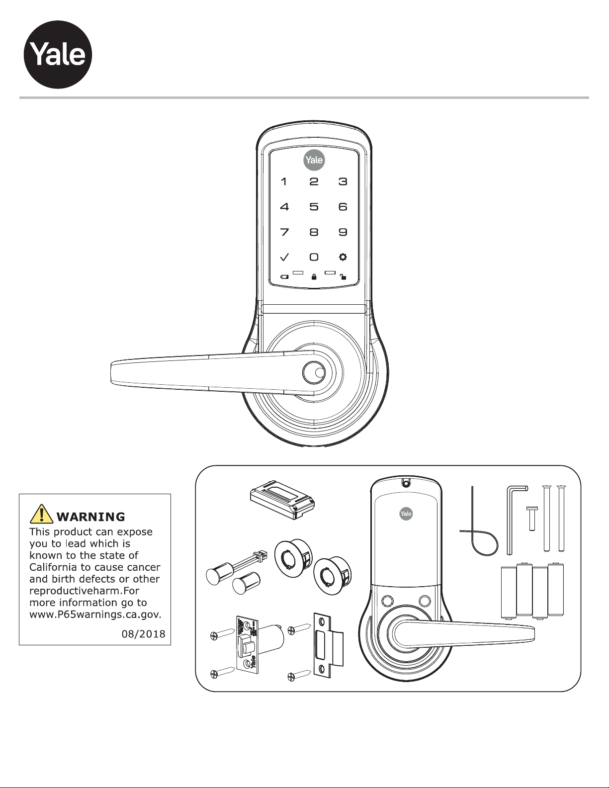
Yale Lift-Tech nexTouch Technical specifications

Retrofitting or modifying this product may impact fire rating, safety features and warranty.
Consult with code specifications to ensure compliance with all codes and ratings.
nexTouch™Keypad Access Cylindrical Lock
Touchscreen and Push Button
Installation and Programming Instructions
AA
AA
AA
AA
Optional
3/32"
Optional
80-9150-0080-010 11-21
Part of ASSA ABLOY

Determine Handing
The hand of a door is determined from the secure side of the door.
The term "secure" means the side from which you initially unlock
and enter.
Left Hand “LH”, Hinges Left.
Open Inward.
Left Hand Reverse "LHR", Hinges Left.
Open Outward.
Right Hand "RH", Hinges Right.
Open Inward.
Right Hand Reverse "RHR", Hinges Right.
Open Outward.
2
80-9150-0080-010 11-21
Part of ASSA ABLOY

Prepare Door
Drill holes 1/2 way
thru door then
complete from other
side to prevent
splitting.
DPS Option
Wood Door:
3/8" Dia. Thru to
Hole in Door Face
*Metal Door:
3/4" Dia. Thru to
Hole in Door Face
*Metal Door Installations
Supplied plastic collar MUST be
installed for DPS to function properly.
1
3
80-9150-0080-010 11-21
Part of ASSA ABLOY

Prepare Frame
DoorFrame
1" Dia. x
1/2" Deep
Frame
Inside
of Door
Frame
3-1/2"
DPS Option
Wood Frame:
3/8" Dia. x 1"
*Metal Frame:
3/4" Dia. x 1"
See Instruction
A7983B
7-16 / 8-32 x 1" UNCWS
x2
*Metal Door Installations
Supplied plastic collar MUST be
installed for DPS to function properly.
2
4
80-9150-0080-010 11-21
Part of ASSA ABLOY

Prepare Inside Lock
Do not take apart the
keypad.
3
2
1
3
5
80-9150-0080-010 11-21
Part of ASSA ABLOY

Curved edge of latchbolt
faces direction door closes.
Install Latchbolt
Inside of Door
7-16 / 8-32 x 1" UNCWS
x2
2-3/8" Latchbolt for thin doors sold separately.
See Installation Options.
Remove Battery Cover
4
5
6
80-9150-0080-010 11-21
Part of ASSA ABLOY

Install Keypad
Inside of Door
Inside of Door
1
2
View from Outside of Door
"T" Tabs
Retractor Pocket
Mounting Flange
Two moving "T" tabs
must be fully captured
in retractor pocket.
Mounting Flanges
must be in Mounting
Flange Pockets.
Mounting Flange Pocket
Mounting
Flange
Mounting Flange Pocket
Thin door gaskets sold separately.
See Installation Options.
Optional DPS
6
7
80-9150-0080-010 11-21
Part of ASSA ABLOY

10-32 x 2-1/2" PFHMS
Install Inside Support
x2 Do Not
Overtighten Screws
Inside of Door
Optional DPS
7
8
80-9150-0080-010 11-21
Part of ASSA ABLOY

Attach Cables to Inside Lock
Optional
DPS
Connection
Motor
Connection
Keypad
Connection
8
9
80-9150-0080-010 11-21
Part of ASSA ABLOY

Install Inside Lock
Test Inside Lever Operation
Avoid Crimping
Cables
Thin door gaskets sold separately.
See Installation Options.
9
10
80-9150-0080-010 11-21
Part of ASSA ABLOY

Install Batteries & Cover
Optional Network or Yale
Accentra Key module must
be installed BEFORE
batteries. See Installation
Options.
"Welcome to Yale."
Congratulations, you've installed the
Yale nexTouch™Cylindrical Lock!
10
11
80-9150-0080-010 11-21
Part of ASSA ABLOY

Network or Yale Accentra Key Module
Installation Options
Adjusting for 1-3/8" Door (if necessary)
Privacy DPS Switch
Order 1-3/8" Thin Door Kit: 14-4761-0106
Inside of Door
Door Position Switch Option
enables Privacy feature
Metal Frame/Door Installations
Supplied plastic collars MUST be
installed for DPS to function properly.
O
optional
Inside
Gasket
Outside
Gasket
CAUTION: Cylinders furnished with
nexTouch™ lock for use in 1-3/8"
doors have a tailpiece that is 1/4"
shorter than the standard cylinders
that are furnished for 1-3/4" doors.
Trying to install a standard cylinder
in 1-3/8" door will DAMAGE the lock.
2-3/8" Latchbolt
12
80-9150-0080-010 11-21
Part of ASSA ABLOY
The Yale Accentra Key module
enables access with physical
(cards and fobs) and mobile
credentials ONLY. Creation and use
of User PIN codes are disabled.

Programming Instructions
Inside Lock
Speaker
Privacy
Button
Low Battery Indicator
(Touchscreen)
Keypad
9Volt Battery
Override Terminal
Lockout Mode Indicator
(Touchscreen)
Unlock Indicator
(Touchscreen)
Lock Activation (Touchscreen)
Press Yale logo
Touch keypad with whole hand
Press check key
Lock Activation (Push Button)
Press any key
13
80-9150-0080-010 11-21
Part of ASSA ABLOY

Press
Press
Press
Activate Lock
Enter 4-8 digit
Master PIN Code.
"Register Master
Code. Press the gear
key to continue."
"Enter a 4-8 digit
PIN code. Press the
gear key to continue."
"Registered."
"Completed."
Creating Master PIN Code
1Creating a Master PIN Code must be performed upon installation or after resetting the
lock to factory default. Programming and use of lock is not possible until this step has
been successfully completed.
14
80-9150-0080-010 11-21
Part of ASSA ABLOY

Activate Lock "Menu Mode,
enter number."
Creating User PIN Codes
Master PIN code must be created first.
*Max User Codes = 500
Enter Master
PIN code
Press
Press
Press
"Press 1 to
register a code."
"Register User code.
Press the gear key
to continue." Press
Press
"Register User code.
Press the gear key
to continue."
"PIN code registration.
Enter a 4-8 digit PIN code.
Press the gear key
to continue."
15
80-9150-0080-010 11-21
Part of ASSA ABLOY
The Yale Accentra Key module enables access with physical (cards and fobs) and
mobile credentials ONLY. Creation and use of User PIN codes are disabled.
2a

Creating User PIN Codes con't
Press
Adding more User Codes:
Enter 4-8 digit PIN code
Press
To end programming:
Press
"Registered.
Press the check key to
complete. Press the gear
key to continue."
Enter 4-8 digit PIN code
followed by
"Completed."
"Registered.
Press the check key to
complete. Press the gear
key to continue."
16
80-9150-0080-010 11-21
Part of ASSA ABLOY
2b

3Locking & Unlocking Door with
Registered Master or User PIN Code
Enter PIN Code
Press
Activate Lock
17
80-9150-0080-010 11-21
Part of ASSA ABLOY
The Yale Accentra Key module enables access with physical (cards and fobs) and
mobile credentials ONLY. Creation and use of User PIN codes are disabled. Master
PIN code is only used for programming and configuring lock with Yale Accentra
Multi-Family configuration app and will not unlock door. When lock is configured
into Accentra, "#2" and "#6" will no longer be visible when in "menu" mode.

4
Testing Outside Lever Operation
Locking Door with Privacy Button
18
80-9150-0080-010 11-21
Part of ASSA ABLOY

Resetting Lock to Factory Default
1. Remove inside lever with the
supplied lever removal tool.
2. Remove the battery cover with
supplied hex wrench and then
remove batteries.
3. Remove network module if installed.
4. Remove the 10-32 x 3/4" pan
head screw from the center of
the battery housing.
5. Remove the inside lock
from the door to access the
reset button on back of
inside lock. Cables may stay
connected. (See illustration
above for location of the reset
button.)
6. Reinstall four (4) AA batteries.
7. Press the reset button for 3
seconds.
8. While continuing to press the
reset button, temporarily
remove one (1) AA battery.
9. Reinstall the battery.
10. Release reset button and wait
approximately 15 seconds.
Speaker will announce
"Welcome to Yale."
11. Reassemble inside lock and
lever.
12. If utilizing a network module,
remove batteries. Insert module.
Reinstall batteries.
Inside Lock
When lock is reset to factory defaults all PIN codes (including the Master PIN code*) are deleted
and all programming features are reset to original default settings (see Factory Settings).
Upon reset, Master PIN Code creation is the only option available and must be performed prior to
any other programming of the lock.
Lever Removal Tool Hex Wrench
Button
Reset
IMPORTANT: The Reset Button is located on Inside Lock.
The keypad remains assembled.
19
80-9150-0080-010 11-21
Part of ASSA ABLOY

All Code Lockout Mode: This feature is enabled by the Master PIN code. When enabled, it restricts all user
(except Master) PIN code access. When attempting to enter a code while unit is in Lockout, there will be
an audible lock response. The touchscreen keypad will display a RED locked padlock.
(Main Menu selection #6.)
Automatic Re-lock Time: After a successful unlock, unit will re-lock automatically after 3 seconds or for a
duration selected in Advanced Lock Settings (Main Menu selection #3 then #1).
Eco Mode: When enabled, Eco Mode puts unit in low power mode extending life of battery.
Language Setting Mode: Choose English (1), Spanish (2) or French (3) for lock's voice prompts. (Main
Menu selection #5.)
Low Battery: When battery power is low, the Low Battery Warning indicator is a flashing red battery icon
on the touchscreen keypad and the Yale logo will flash red on the push button keypad. If battery power is
completely lost, use 9Volt battery override. To use 9V battery override apply 9V battery, in either direction,
to terminals on the keypad for backup power option. Activate the lock and enter your pin code to unlock
door.
Master PIN Code: The Master PIN code is used for programming and for feature settings. It must be
created prior to programming the lock. The Master PIN code will also unlock/lock the lock except when
configured to Accentra system.
Network Module Setting: With optional Network Module installed, this setting becomes available (Main
Menu selection #7 or #0 with Accentra Module) and allows the lock to connect with a network controller.
One Touch Locking: When unit is unlocked, activating the lock will lock unit (during Automatic Re-lock
duration or when Automatic Re-lock is disabled). When One-Touch Re-lock is not in use (disabled), any
valid PIN code will re-lock the lock. (Main Menu selection #3 then #3.)
Passage PIN Code: When used to unlock, lock will remain unlocked/open. Lock cannot be locked/secured
until Passage code is entered again.
Privacy Button to Lock Door: A press of this button will lock the door.
Privacy Mode: With optional Door Position Switch installed, Privacy Mode enabled thru Menu Mode and
door closed, all keypad functions can be disabled with a press of the Privacy Button. Privacy Mode is
disabled by default. Enable Privacy Mode thru Main Menu selection #3 then #4. With door closed, press
and hold the privacy button until voice prompt indicates Privacy Mode is enabled. Privacy Mode duration
ends when door is opened and voice prompt indicates Privacy Mode is disabled.
Shut Down Time: Unit will shut down for sixty (60) seconds and not allow operation after wrong code
entry limit (5 attempts) has been met. When unit is in Shut down, the keypad will be flashing.
Tamper Alert: Audible alarm sounds if attempting to forcibly remove outside lock from door.
User PIN Code: The User code operates the lock. Maximum number of user codes is 500.
Volume Setting Mode: The volume setting for PIN code verification is set to HIGH (1) by default;
otherwise it can be set to Low (2) or Silent (3) for quiet areas. (Main Menu selection #4.)
Wrong Code Entry Limit: After five (5) unsuccessful attempts at entering a valid PIN code, the lock will
not accept a PIN code for the duration of the shut down time. The touchscreen keypad will flash, and a red
padlock symbol will be at the bottom of the keypad. The push button keypad will flash and the Yale icon
will flash blue for the shut down period. The keypad will be available after the shut down time is complete.
Definitions
20
80-9150-0080-010 11-21
Part of ASSA ABLOY
Table of contents
Popular Door Lock manuals by other brands

Schlage
Schlage Ease S2 quick start guide

Sargent and Greenleaf
Sargent and Greenleaf 3007 Direct Drive Basic Programming & Operations Guide

Transmitter Solutions
Transmitter Solutions GEM-300 installation manual

Lockly
Lockly DEADBOLT EDITION PGD1128 installation manual

DORIC
DORIC DS2800 installation guide

Mul-t-lock
Mul-t-lock HaspLock Diamond Installation and service instructions

Yale
Yale Real Living YRL210 Installation and programming instructions

Anviz
Anviz bl100 installation guide

LOCKEY
LOCKEY SUMO GL2LINX installation instructions

Stuv
Stuv 3.31.270 Series Assembly instructions

Assa Abloy
Assa Abloy Corbin Russwin MP6600 Series installation instructions

Allegion
Allegion Falcon K12 installation instructions