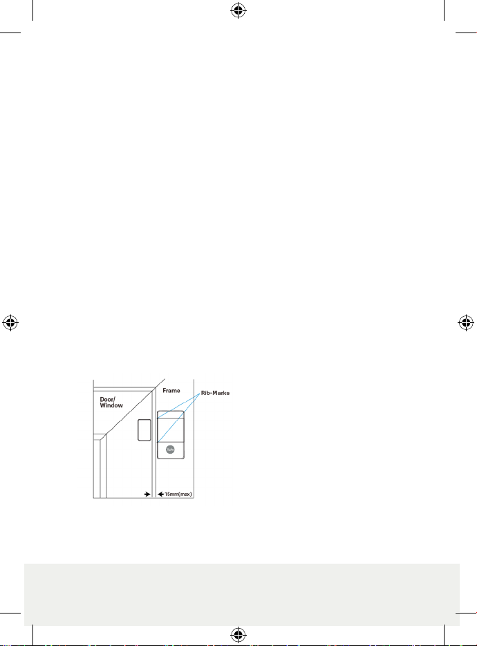
1. Rib Marks
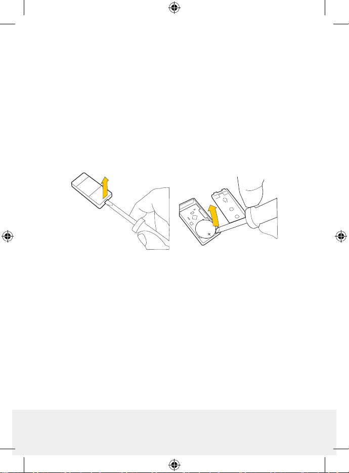
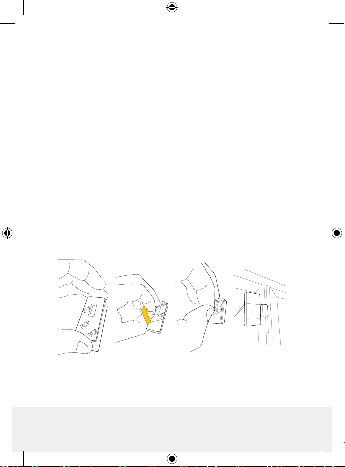
2. Battery Insulator
3. Learn / Test Button
4. Red LED Indicator
5. Tamper Switch
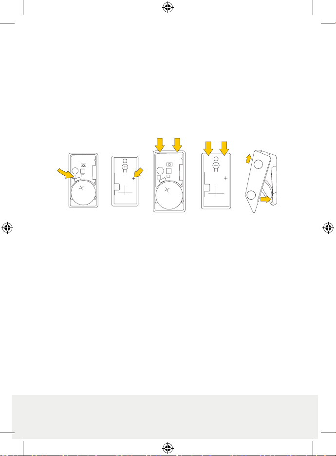
6. Battery
8. Tamper Compression Mark
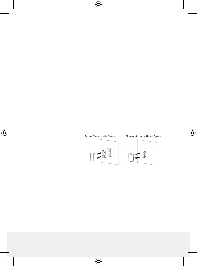
10. Magnet Spacer
1
Mini Door Contact (MDC-3) User Manual
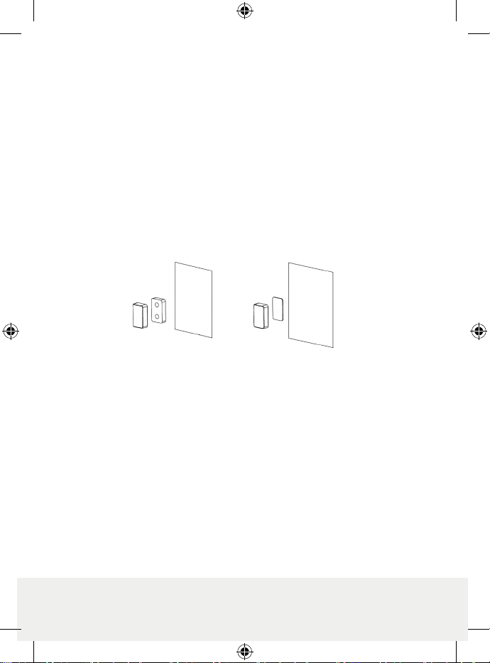
The Mini Door Contact monitors the opening/closing of specified devices (e.g. door or window). The Door Contact is fixed to the
monitored device frame with an actuating magnet fixed to the device. When the door or window opens, the magnet moves away
from the Door Contact, activating an internal magnetic switch causing the Door Contact to transmit alarm signal to the Control
Panel. The device also has the capabilities of communicating signal problems along with low battery situations.
The Door Contact design is consisted of a front cover and a back cover. The front cover(back) contains all electronics and the
back cover provides a means for fixing the device. An enclosed PCB tamper switch provides tamper protection against
unauthorized device opening.
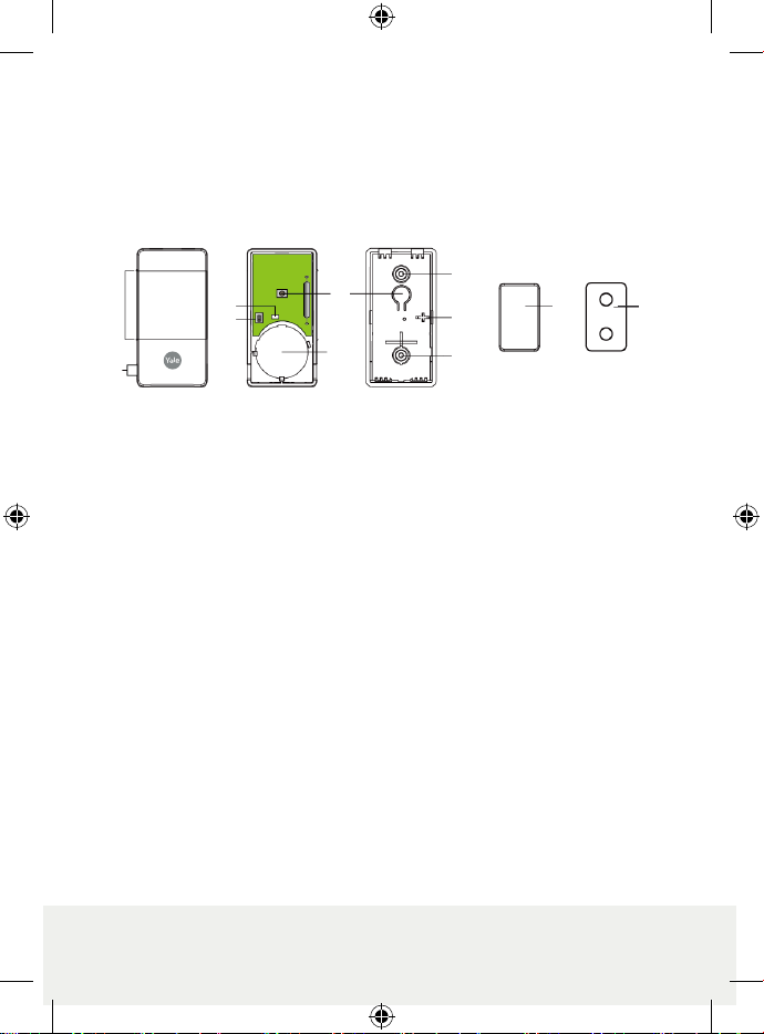
Identifying the parts
1. Rib Marks
2. Battery Insulator
3. Learn / Test Button
- Press the Test button to transmit a learn code.
- Press the Test button once to enter Test Mode for 3 minutes.
4. Red LED Indicator
5. Tamper Switch
6. Battery
7. Mounting Holes (Knockouts)
8. Tamper Compression Mark
9. Magnet
10. Magnet Spacer
Accessories Included
a) 1 Magnet
b) 1 double-sided adhesive Magnet Spacer
c) 2 Screws
d) 4 Wall Plugs
e) 1 double-sided adhesive Velcro tape (for Door Contact)
f) 1 double-sided adhesive tape pad (for Magnet)
g) 2 Magnet mounting screws
Features
LED Indicator
In Normal operation mode, the LED indicator remains off except in the following situations:
When Door Contact’s Tamper switch is triggered.
When the Door Contact is activated with either Tamper or Low battery condition.
When the Door Contact is activated and transmitting the signal under the Test mode.
Supervision
The Door Contact will automatically transmit Supervisory signals periodically to the Control Panel at random
intervals of 90 to 110 minutes in Normal Operation Mode.
If the Control Panel has not received the signal from the Door Contact for a preset period of time, the Control
Panel will indicate that particular Door Contact is experiencing an out-of-signal problem.