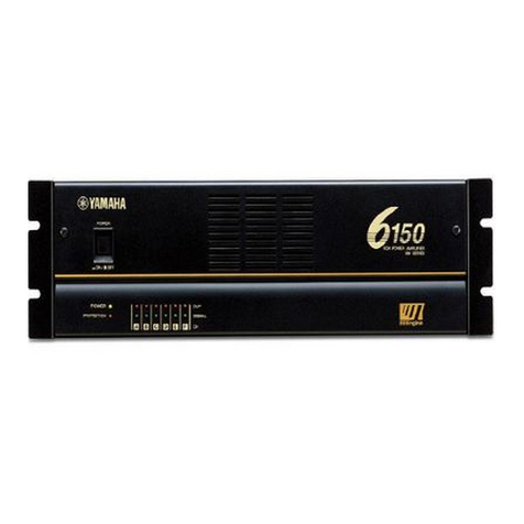
Yamaha CP2000 User manual

SERVICE MANUAL
PA 011553
HAMAMATSU, JAPAN
1.222K-496 Printed in Japan '00.11
CONTENTS
SPECIFICATIONS···································································· 3
PANEL LAYOUT······································································· 4
CIRCUIT BOARD LAYOUT······················································ 5
WIRING····················································································· 6
DIMENTIONS ··········································································· 7
BLOCK DIAGRAM···································································· 8
DISASSEMBLY PROCEDURE················································· 9
IC BLOCK DIAGRAM ····························································· 11
CIRCUIT BOARDS································································· 12
INSPECTIONS········································································ 17
PARTS LIST
OVERALL CIRCUIT DIAGRAM
POWER AMPLIFIER
This document is printed on chlorine free (ECF) paper with soy ink.

CP2000
2
WARNING: CHEMICAL CONTENT NOTICE!
The solder used in the production of this product contains LEAD. In addition, other electrical/electronic and/or plastic (where
applicable) components may also contain traces of chemicals found by the California Health and Welfare Agency (and possibly
other entities) to cause cancer and/or birth defects or other reproductive harm.
DO NOT PLACE SOLDER, ELECTRICAL/ELECTRONIC OR PLASTIC COMPONENTS IN YOUR MOUTH FOR ANY REASON
WHAT SO EVER!
Avoid prolonged, unprotected contact between solder and your skin! When soldering, do not inhale solder fumes or expose eyes
to solder/flux vapor!
If you come in contact with solder or components located inside the enclosure of this product, wash your hands before handling
food.
IMPORTANT NOTICE
This manual has been provided for the use of authorized Yamaha Retailers and their service personnel. It has been assumed that
basic service procedures inherent to the industry, and more specifically Yamaha Products, are already known and understood by
the users, and have therefore not been restated.
WARNING: Failure to follow appropriate service and safety procedures when servicing this product may result in personal
injury, destruction of expensive components and failure of the product to perform as specified. For these
reasons, we advise all Yamaha product owners that all service required should be performed by an authorized
Yamaha Retailer or the appointed service representative.
IMPORTANT: This presentation or sale of this manual to any individual or firm does not constitute authorization, certification,
recognition of any applicable technical capabilities, or establish a principal-agent relationship of any form.
The data provided is belived to be accurate and applicable to the unit(s) indicated on the cover. The research engineering, and
service departments of Yamaha are continually striving to improve Yamaha products. Modifications are, therefore, inevitable and
changes in specification are subject to change without notice or obligation to retrofit. Should any discrepancy appear to exist,
please contact the distributor's Service Division.
WARNING: Static discharges can destroy expensive components. Discharge any static electricity your body may have
accumulated by grounding yourself to the ground bus in the unit (heavy gauge black wires connect to this bus).
IMPORTANT: Turn the unit OFF during disassembly and parts replacement. Recheck all work before you apply power to the
unit.
WARNING
Components having special characteristics are marked and must be replaced with parts having specification equal to those
originally installed.
IMPORTANT NOTICE FOR THE UNITED KINGDOM
Connecting the Plug and Cord
IMPORTANT. The wires in this main lead are coloured in
accordance with the following code:
BLUE: NEUTRAL
BROWN: LIVE
As the colours of the wires in the main lead of this apparatus may not
correspond with the coloured markings identifying the terminals in
your plug, proceed as follows:
The BLUE wire must be connected to the terminal that is marked with
the letter N (or coloured BLACK).
The BROWN wire must be connected to the terminal that is marked
with the letter L (or coloured RED).
Be certain that neither core is connected to the earth terminal of the
three pin plug.
SPECIFICATIONS
CP2000
3
Power Output Level 8 Ω/STEREO
1 kHz, THD+N=1 % 4 Ω/STEREO
8 Ω/BRIDGE
1 kHz 2 Ω/STEREO
20 ms, non-clip 4 Ω/BRIDGE
Power Bandwidth THD+N=0.2 % (half power)
Total Harmonic Distortion (THD+N) 4–8 Ω/STEREO
20 Hz–20 kHz (half power) 8 Ω/BRIDGE
Intermodulation Distortion 4–8 Ω/STEREO
60 Hz:7 kHz, 4:1, half power 8 Ω/BRIDGE
Frequency Response 8 Ω, Po=1W
Channel separation Half power, RL=8 Ω
LEVEL=max., input 600 Ωshunt
Residual Noise LEVEL=min., 12.7 kHz LPF, IHF-A network
S/N Ratio 12.7 kHz LPF
Damping Factor RL=8 Ω, 1 kHz
Sensitivity LEVEL=max., rated power into 8 Ω
Voltage Gain LEVEL=max.
Input Impedance
Front panel
Controls Rear panel
Input
Connectors Output
POWER
PROTECTION
TEMP
Indicators CLIP
SIGNAL
Protection Circuit
Fan Circuit
Limiter Circuit
Power requirements
Idle Power Consumption
1/8 Power Consumption (4 Ω)
Maximum Power Consumption (4 Ω)
Dimensions (W x H x D)
Weight
AC Power cord length
450 W + 450 W
650 W + 650 W
1300 W
1000 W + 1000 W
2000 W
10 Hz—40 kHz
0.1%
0.1%
0 dB, +0.5 dB, -1 dB f=20 Hz—50 kHz
≥70 dB, 1 kHz
≤-70 dB
104 dB
≥200
+4 dB
33.8 dB
30 kΩ(balanced), 15 kΩ(unbalanced)
POWER switch (push on/push off)
LEVEL attenuator (31 position) x2
Mode switch (STEREO/BRIDGE/PARALLEL)
YAMAHA SPEAKER PROCESSING switch (ON/OFF)
XLR-3-31 type (balanced) L+R
1/4" phone jack (balanced) L+R
1/4" phone jack L+R
5-way binding post x1
x1 (green)
x1 (red)
x1 (red) heatsink temp ≥85 °C
x2 (red)
x2 (green) output voltage ≥2 V
x2 (yellow) output voltage ≥20 V
POWER switch on/off mute
DC detection
TEMP (heatsink temp ≥90 °C)
PC limiter: RL ≤1 Ω
Stop–low speed (50 °C)–variable–high Speed (70 °C)
Comp: THD≥0.5 %
U.S.A. & Canada 120 V AC, 60 Hz
Europe 230 V AC, 50 Hz
Australia 240 V AC, 50 Hz
30 W
400 W
2000 W
480 x 88 x 416 mm (18.9 x 3.46 x 16.4 inches)
14 kg (30.9 lbs)
2.3 m
* 0 dB=0.775 V rms, half power = 1/2 output level.

1
8
9 10 12
11
2 3 4 5
6 7
1POWER switch
2POWER indicator
3PROTECTION indicator
4TEMP indicator
5Level controls
6CLIP indicators
7LEVEL indicators
8INPUTs
9Mode switch
10 YAMAHA SPEAKER PROCESSING switch
11 SPEAKERS connectors
12 GND terminal
CP2000
4
PANEL LAYOUT
Front Panel
Rear Panel

CIRCUIT BOARD LAYOUT
CP2000
5
70
80
CN615
CN303 CN305 CN304 CN302
CN616
CN606
CN607
CN608
CN612
CN610
CN609
CN611
CN614
CN313
CN603
CN604
CN605
CN601 CN602
CN301
CN102
CN105
CN106
CN101
CN103
CN104
CN306
CN617
AC 4/6
IN PA
AC 6/6 AC 5/6
AC 1/6
AC 2/6
AC 3/6
Power transformerFront panel Fan
AC 4/6-CN615 IN-CN303 7P 100mm
Connector AssemblyPart No.
MF107100
Location Destination Remarks
AC 6/6-CN617 IN-CN305 9P 120mmMF109120
70
80
3NC2-V617020
1 1
23
U, V, T H, W, B A
BR
WH
BL
BE
BE
BR
RE
BE
BR
• Wire Colors
1
2
3
2

to Rear panel
AC cord
AC 4/6
IN
PA
AC 6/6 AC 5/6 AC 1/6
AC 2/6
AC 3/6
FAN
KEC-92573
POWER
TRANSFORMER POWER
switch
3
CP2000
6
WIRING

DIMENTIONS
CP2000
7
88
480
410
416
Unit: mm

KEC-92572 1
CHANNEL L
(BRIDGE)
(PARALLEL)
CHANNEL R
INPUT
JK301
JK303
12
3
2
3
1
JK302
JK304
12
3
2
57
6
+
-
3
1BA
IC301
POWER
LD602 POWER CIRCUIT
AC Cord
POWER SW
SW601
31
2
+
-
BA
IC301
1
3
SW302
IC302
1
3
IC303
VR602
VR601
SW301
ON
OFF
CHANNEL
L
ATT
YAMAHA
SPEAKER
PROCESSING
SW302
ON
OFF
INV
CLIP
LD604
LD605
LD606
JK601
SP601
JK602
LD608
LD609
LD601
SIGNAL
SIGNAL
LD603
CLIPLD607
CHANNEL
R
ATT
PARALLEL
BRIDGE
STEREO
Limiter
Lch Power Amp
Limiter
AC 4/6 AC 3/6, 5/6, 6/6
AC 1/6 AC 2/6,
CN615
IC302
76
CN303
IN
CN302
CN614 +B
E
-B
+24
E
-24
Rch Power Amp
Temperature
Sensor
(Heat Sink) Protection
Circuit
CN304
CN616
PROTECTION
TEMP
PA
PA
W607
CN105
RY101
W609
CN106
RY102
SPEAKERS
CHANNEL L
L+R BRIDGE
CHANNEL R
FAN
Power transformer
CP2000
8
BLOCK DIAGRAM

(Fig. 1)
(Fig. 2)
(Fig. 3) (Fig. 4)
[420]
[420] [420]
[420]
[420]: Bind Head Tapping Screw-B 4.0X8 MFZN2BL (EG340190)
[290]: Bonding Tapping Screw-B 3.0X8 MFZN2BL (VN413300)
[300]: Bind Head Tapping Screw-B 3.0X12 MFZN2BL (VQ074600)
[320]: Bind Head Tapping Screw-B 3.0X8 MFZN2BL (EP600190)
[103]: Bind Head Tapping Screw-B 4.0X8 MFZN2BL (EG340190)
[140]: Bind Head Tapping Screw-B 3.0X8 MFZN2BL (EP600190)
[80A]: Bind Head Screw A4.0X8 MFZN2BL (VP156800)
[120]: Bind Head Tapping Screw-B 3.0X8 MFZN2BL (EP600190)
[160]: Bonding Tapping Screw-B 4.0X8 MFZN2BL (VR779900)
[180]: Bind Head Tapping Screw-B 3.0X8 MFZN2BL (EP600190)
Top cover
<Top view>
<Rear view> <Side view>
[180][160]
IN
AC 3/6
AC 2/6
[290A] [320] [300] [320]
[A] [B]
[290B]
Speaker terminal cover [B]
AC 3/6
[80A]
[120]
DB angle
DB angle
[140][103]
[C]
Transformer holder PA unitPower transformer
DISASSEMBLY PROCEDURE
CP2000
9
1. Top Cover (time required: about 3 minutes)
1-1 Remove the nine (9) screws marked [420]. The top cover
can then be removed. (Fig. 1)
2. IN Circuit Board(time required: about 8 minutes)
2-1 Remove the top cover. (See procedure 1.)
2-2 Remove the six (6) screws marked [180], the four (4) screws
marked [290A] and the two (2) hexagonal nuts marked [A].
The IN circuit board can then be removed. (Fig. 2, Fig. 3)
3. AC3/6 Circuit Board
(time required: about 10 minutes)
3-1 Remove the top cover. (See procedure 1.)
3-2 Remove the two (2) screws marked [320]. The speaker
terminal cover can then be removed. (Fig. 3)
3-3 Remove the screw marked [290B], the two (2) screws
marked [300] and the two (2) hexagonal nuts marked [B].
The AC3/6 circuit board can then be removed. (Fig. 3)
4. AC2/6 Circuit Board
(time required: about 15 minutes)
4-1 Remove the top cover. (See procedure 1.)
4-2 Remove the AC3/6 circuit board. (See procedure 3.)
4-3 Remove the screw marked [80A], the three (3) screws
marked [120] and the two (2) screws marked [140]. The
AC2/6 circuit board and the DB angle can then be removed.
(Fig. 2, Fig. 4)
5. Power Transformer
(time required: about 8 minutes)
5-1 Remove the top cover. (See procedure 1.)
5-2 Remove the two (2) screws marked [103] and the
hexagonal bolt marked [C]. The transformer holder and
the power transformer can then be removed. (Fig. 2, Fig. 4)

[250]
(Fig. 7)
[250]
Front panel
<Front View>
[250]: Oval Head Screw 4.0X8 MFZN2BL (VS153600)
8. Front Panel (time required: about 5 minutes)
8-1 Remove the top cover. (See procedure 1.)
8-2 Remove the six (6) screws marked [250]. The front panel
can then be removed. (Fig. 7)
9.
AC1/6, AC4/6, AC5/6 and AC6/6 Circuit Board
(time required: about 20 minutes)
9-1 Remove the top cover. (See procedure 1.)
9-2 Remove the front panel (See procedure 8.)
9-3 AC1/6 Circuit Board:
Pull out the power switch knob. (Fig. 6)
Remove the two (2) screws marked [60]. The AC1/6 circuit
board can then be removed. (Fig. 6)
9-4 AC4/6 Circuit Board:
Pull out the attenuation knobs. (Fig. 6)
Remove the two (2) hexagonal nuts marked [D]. The AC4/6
circuit board can then be removed. (Fig. 6)
9-5 AC5/6 Circuit Board:
Remove the screw marked [100A]. The AC5/6 circuit board
can then be removed. (Fig. 6)
9-6 AC6/6 Circuit Board:
Remove the screw marked [100B]. The AC6/6 circuit board
can then be removed. (Fig. 6)
• PA Unit [80B]
[80B]
[80B]
[80B]
[80B]
[80B]
(Fig. 5)
Transistor holder (L)
Transistor holder (R)
[40]
PA
PA
[40]: Bind Head Screw SP 3.0X8 MFZN2BL (EG330290)
[80B]: Bind Head Tapping Screw-B 3.0X12 MFZN2BL (VQ074600)
(Fig. 6)
[50]: Bind Head Screw 4.0X8 MFZN2BL (EG340360)
[60]: Bind Head Screw 3.0X8 MFZN2BL (VB659000)
[100]: Bind Head Tapping Screw-B 3.0X8 MFZN2BL (EP600190)
[60] x 2
[D]
[50]
Fan
AC 1/6
AC 4/6
Power switch
knob
Attenuation knob
AC 5/6 AC 6/6
[100A]
[100B]
CP2000
10
6. PA Unit & PA Circuit Board
(time required: about 15 minutes)
6-1 Remove the top cover. (See procedure 1.)
6-2 Remove the six (6) screws marked [160]. The PA unit can
then be removed. (Fig. 2)
6-3 Remove the eighteen (18) screws marked [80B]. And then
remove the left and right transistor holders from the PA unit.
(Fig. 5)
6-4 Remove the six (6) screws marked [40]. And then remove
the PA circuit board from the PA unit. (Fig. 5)
7. DC Fan (time required: about 8 minutes)
7-1 Remove the top cover. (See procedure 1.)
7-2 Remove the PA unit. (See procedure 6-2.)
7-3 Remove the two (2) screws marked [50]. The fan can then
be removed. (Fig. 6)

IC BLOCK DIAGRAM
CP2000
11
M5238AP (XM085A00)
Dual Operational Amplifier
IN: IC301
NJM2068L-D (XM356A00)
Dual Operational Amplifier
IN: IC302, 303
1
2
3
4-V
8
7
6
5
Output A +V
Non-Inverting
Input A
-DC Voltage Supply
+DC Voltage
Supply
Output B
Inverting
Input B
Non-Inverting
Input B
Inverting
Input A
+-
+- 1
A
2345678
OUT
A-IN
A+IN
A+IN
B-IN
BOUT
B
-V +V
-
+
B
-
+
CIRCUIT BOARDS CONTENTS
AC 1/6 Circuit Board (XY969B0)················································································ 12
AC 2/6 Circuit Board (XY969B0)················································································ 16
AC 3/6 Circuit Board (XY969B0)················································································ 13
AC 4/6 Circuit Board (XY969B0)················································································ 12
AC 5/6 Circuit Board (XY969B0)················································································ 12
AC 6/6 Circuit Board (XY969B0)················································································ 12
IN Circuit Board (XY968B0) ······················································································· 12
PA Circuit Board (XY970B0)······················································································ 14
Note: See parts list for details of circuit board component parts.

to IN-CN303
Component side
LEVEL CONTROL L LEVEL CONTROL R
to IN-CN304
to IN-CN305
Component side
Component side
Component side
POWER ON/OFF
to AC 2/6-
CN601
to AC 2/6-
CN603
to AC 2/6-
CN602
POWER
PROTECTION
TEMP
LEVEL L
LEVEL R
CLIP L
CLIP R
A
A'
to FAN
to AC6/6
-CN617
to AC 5/6
-CN616
to AC 4/6
-CN615
to AC 2/6-CN614
CP2000
12
CIRCUIT BOARDS
IN: 3NA-V607200
AC 1/6, 4/6, 5/6, 6/6: 3NA-V607220 1
2
IN Circuit Board
AC 4/6 Circuit BoardAC 1/6 Circuit Board
AC 5/6 Circuit Board
AC 6/6 Circuit Board

INPUT
CHANNEL R
CHANNEL L
YAMAHA
SPEAKER
PROCESSING
PARALLEL
BRIDGE
STEREO
(BRIDGE)
ON
OFF
A
A'
to PA-CN101
Component side
CP2000
13
Component side
SPEAKERS
(-) BRIDGE (+)
12 21
CHANNEL L CHANNEL R
to PA-CN106
to AC 2/6-CN612to PA-CN105 to REAR PANEL
IN: 3NA-V607200
AC 3/6: 3NA-V607220 1
2
AC 3/6 Circuit Board

CP2000
14
B
B'
CN101:
CN102: to IN-CN306
to AC 2/6-W604 CN103:
CN104: to AC 2/6-W605
to AC 2/6-W606 CN105:
CN106: to AC 3/6-W607
to AC 3/6-W609
PA Circuit Board
3NA-V60721 1

CP2000
15
B
B'
Component side
3NA-V60721 1

Component side
CN601:
CN602:
CN603:
CN604:
CN605:
to AC 1/6-W601
to AC 1/6-W602
to AC 1/6-W603
to AC cord (L)
to AC cord (N)
CN606:
CN607:
CN608:
CN609:
CN610:
to Power transformer
CN611:
CN612:
W604:
W605:
W606:
to Power transformer
to AC 3/6-W608
to PA-CN102
to PA-CN103
to PA-CN104
to IN-CN301
to Power
transformer
U, V, T
H, W, B
A
BL
CN604
BR
BR
WH
CN605
BE
BE
BR
CN606, CN607
BE
RE
• Wire Colors
CP2000
16
AC 2/6 Circuit Board
3NA-V607220 2

INSPECTIONS
CP2000
17
1. Inspection during stereo mode and parallel mode
1.1 Preparations
1.2 Inspection and adjustment
1.2.1 Fan and temperature indicator
The fan shall operate when the two jumper wires inside the frame marked
FAN-C inside sheet IN are shorted. Next, the temperature indicator shall
come on when the two jumper wires inside the frame marked TM-C are
shorted. (Refer to the figure to the right for FAN-C, TM-C.)
1.2.2 Power on muting time
At t=2.5 ±1 seconds after the power switch is turned on, the muting shall be cancelled and the protection indicator shall go off.
1.2.3 Idling current
Ground the input terminal and adjust VR101 (L ch) and VR102 (R ch) so that the CN108 (L ch) and CN107 (R ch) No. 1 and 2
terminals show DC voltage of Vb=0.5 ±0.1 mV.
Once all inspections have been completed, re-inspect Vb and adjust so that it is Vb=0.5 ±0.1 mV.
1.2.4 Output terminal DC voltage
Ground the input terminal and measure the Vdc (direct current voltage) of the output terminal. It shall be Vdc=0 ±75 mV.
1.2.5 Gain
An output voltage of +24.0 ±0.5 dBu shall be attained when 1 kHz, -10.0 dBu sine wave is input to the input terminal.
This inspection shall also be performed in the PARALLEL mode.
1.2.6 Frequency characteristics
* YAMAHA SPEAKER PROCESSING OFF:
Using 1 kHz as a standard for the output voltage, the output voltage shall be within -0.5 ±0.5 dB at 20 kHz when 20 Hz, 1 kHz,
20 kHz, -10 B dBu sine waves are input to the input terminal.
* YAMAHA SPEAKER PROCESSING ON:
Using 1 kHz as a standard for the output voltage, with the Yamaha speaker processing off, the output voltage shall be within +
6.5 ±1.5 dB when a 70 Hz, -10 dBu sine wave is input to the input terminal.
1.2.7 Total harmonic distortion ratio characteristics
The total harmonic distortion ration shall be THD=1 % or less when a 1 kHz high definition sine wave is input to the input terminal
and the rated output of 650 w + 650 w / 4 ohm (36.4 dBu/ch) has been attained. This inspection shall be completed within 30 seconds.
1.2.8 Channel separation load resistance 8 Ω
When the input terminal for one of the channels has attained a 1kHz, -5dBu sine wave has and that input terminal is grounded by
the introduction of 600 Ωresistance, the measured output voltage of the other channel shall by -70 dB or less, using a output voltage
with (0 dB) as the reference level.
1.2.9 Output noise level
Measure the noise level at the output terminal when the input attenuator has been set to MAX and a input terminal has been grounded
by the introduction of a 600 Ωresistance. It shall be -67 dBu or less. Next, set the input attenuator to MIN and measure. It shall be
-70 dBu or less.
Input attenuator
Input terminal
Mode SW
Yamaha speaker processing
Output terminal
Others
MAX
Cannon connector No. 2 hot; No. 1, 3 ground
Stereo
Off
Resistance load 4 Ω, Non inductance resistor, input capacitance 500 W or more.
Unless otherwise specified, drive both channels unless otherwise specified.
INPA
AC 3/6
AC 2/6
TM-C
FAN-C
<Top View>

1.2.10 Stability
The following conditions shall be met when a 10 kHz, -10dBu rectangular pulse is input and a capacitance of 10 pf ~ 0.47 µF is
connected in parallel with a load resistance of 4 Ω.
Overshoot Vp/Vo 1.8
Ringing: Within 5 waves
Next, when there is only a pure capacitance of 10 pf ~ 0.47 µF the following conditions shall be met.
Vp/Vo 2.5
Ringing: There shall be convergence within 7 waves and no oscillation, etc.
1.2.11 Protection circuit
The protection circuit shall operate and the relay shall not open when a 10 Hz, +5.4 dBu sine wave is input and the output wave is
made to clip. Next, the protection circuit shall operate within two seconds and break the output when a 1 Hz, 0.0 dBu sine wave is
input. In addition, when the input signal is cut, it shall automatically recover within 10 seconds.
1.2.12 Efficiency
(1) The primary electrical power shall be measured and be within the range shown below when a 1 kHz, -6.6 dBu sine wave is input
to the input terminal.
330 W ±50 W (U: 4.0 A ±0.6 A, H: 2.0 A ±0.3A)
(2) The primary electrical power shall be measured and be within the range shown below when the input terminal is grounded by the
introduction of the input terminal.
25 W ±10 W (U: 0.33 A ±0.13 A, H: 0.20 A ±0.08 A)
1.2.13 PC limiter and comp
Input a 1 kHz, -1.5 dBu sine wave to the input terminal and connect 1 Ω(±5 %) as a load to the output terminal. Under these conditions,
a 10 V Vrms 16 V sine wave shall be attained at the output. The total harmonic distortion ratio shall be THD=5 % or less.
Also at this time, the clip indicator shall come on. This inspection shall be completed within 30 seconds.
1.2.14 Signal indicator
The green signal indicator shall come on when a 1 kHz, -23 dBu sine wave is input.
In addition, the green and yellow signal indicators shall come on when a 1 kHz, -4 dBu sine wave is input.
2. Bridge mode
2.1 Preparations
2.2 Inspection
2.2.1 Gain
An output voltage of +24.0 ±1.0 dBu shall be attained when a 1 kHz, -10 dBu sine wave is input to the input terminal.
<
=
<
=
<
=<
=
CP2000
18
Input attenuator
Input terminal
Mode SW
Yamaha speaker processing
Output terminal
Load resistance
Measurement connection
L channel only operates. Set to MAX.
L channel cannon connector (No. 2 hot, No. 1, 3 ground)
Bridge
Off
Use L channel +, R channel +.
4 Ω+ 4Ω, Non inductance resistor, input capacitance 500 W or more.
Set to a floating ground and connect at center point of load resistance.
SPEAKERS
INPUT
MEASURING
INSTRUMENT
GND

CP2000
19
2.2.2 Frequency characteristics
Using 1 kHz as a standard for the output voltage, the output voltage shall be within -0.5 ±0.5 dB at 20 kHz when 20 Hz, 1 kHz, 20
kHz, -10 B dBu sine waves are input to the input terminal.
2.2.3 Total harmonic distortion ratio characteristics
The total harmonic distortion ration shall be 1 % or less when a 1 kHz high definition sine wave is input to the input terminal and the
output voltage of 36.4 dBu has been attained. This inspection shall be completed within 30 seconds.
2.2.4 Output noise level
Measure the noise level at both terminals of the load resistance when the input attenuator has been set to MAX and the input
terminal has been grounded by the introduction of a 600 Ωresistance. It shall be -60 dBu or less. Next, set the input attenuator to
MIN and measure. It shall be -60 dBu or less.
3. Process after completion of inspection
Close up the input attenuator in a half-clockwise direction.
Set YAMAHA SPEAKER PROCESSING to on.
Set the mode switch to STEREO.
4. Others
A DIN audio filter shall be used for the measurement of the noise level.
0 dBu=0.775 V

CONTENTS
OVERALL ASSEMBLY······························································································································2
ELECTRICAL PARTS ·························································································································5~12
PARTS LIST
WARNING
Components having special characteristics are marked and must be replaced with parts having
specification equal to those originally installed.
A: Australian model
B: British model
C: Canadian model
D: German model
E: European model
F: French model
H: North European model
I : Indonesian model
J: Japanese model
M: South African model
O: Chinese model
Q: South-east Asia model
T: Taiwan model
U: U.S.A. model
V: General export model (110 V)
W: General export model (220 V)
N,X:General export model
Y: Export model
Notes: DESTINATION ABBREVIATIONS
•The numbers in “ QTY ” show quantities for each unit.
•The parts with “ - - ” in “ PART NO. ” are not available as spare parts.
•The mark “ ” in the remarks column indicates that these parts are interchangeable.
•The second letter of the shaded ( ) part number is O, not zero.
•The second letter of the shaded ( ) part number is I, not one.
POWER AMPLIFIER
Other manuals for CP2000
2
Table of contents
Other Yamaha Amplifier manuals

Yamaha
Yamaha MA2030 User manual

Yamaha
Yamaha DG-Stomp User manual

Yamaha
Yamaha AS1000 - Amplifier User manual

Yamaha
Yamaha AVC-50RS User manual

Yamaha
Yamaha DSP-Z11 User manual

Yamaha
Yamaha P1150 User manual

Yamaha
Yamaha M-60 User manual

Yamaha
Yamaha AX-300 User manual

Yamaha
Yamaha PC4800N User manual

Yamaha
Yamaha A-S201 User manual

Yamaha
Yamaha MX-1 User manual

Yamaha
Yamaha CX-1000 User manual

Yamaha
Yamaha C-4 User manual

Yamaha
Yamaha CX-A5200BL User manual

Yamaha
Yamaha DSP-AX620 User manual

Yamaha
Yamaha AX-596 User manual

Yamaha
Yamaha T-100 Guide

Yamaha
Yamaha DSP-A500 User manual

Yamaha
Yamaha AX-397 User manual

Yamaha
Yamaha DSP-A970 User manual