Yamaha MX825V-EFI User manual
TABLE OF CONTENTS
Model :MX825V-EFI
2
Feature Map………………………………………. 3
Specification..…………..……………………….. 4
Features & Structures.………………………. 5~17
FI Diagnostic Tool………………………………. 18
Wiring Schematic………………………………. 21
Equipment Information…………………….. 22
Oil Pressure Switch……………………………. 23
Valve Shim Adjustment Overview……… 24
Valve Adjustment Procedure…………….. 25
Fuel Pump Information……………………… 26
MX825 Owner’s Manual……………………. 27
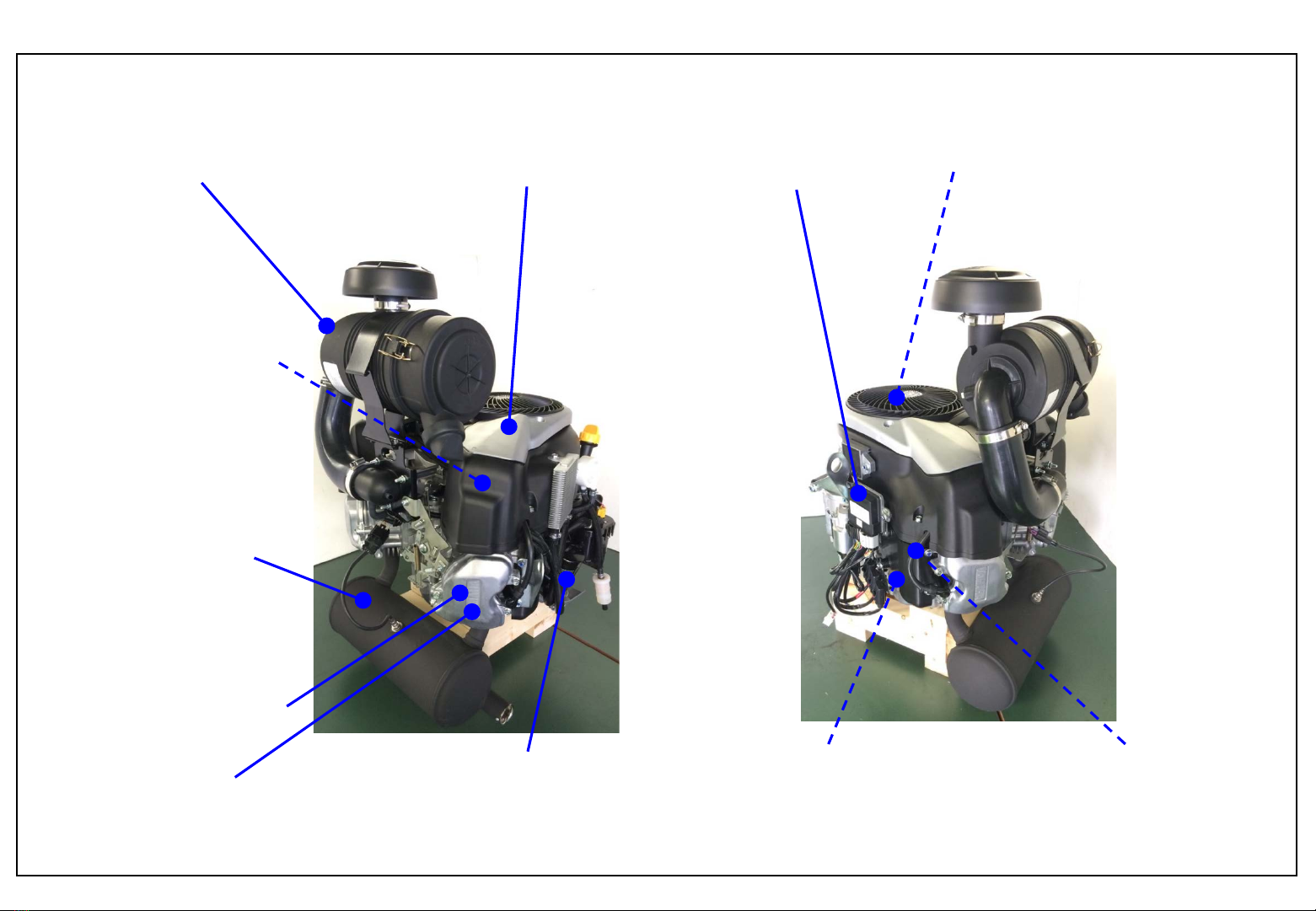
FEATURE MAP
Model :MX825V-EFI
3
3 valves(IN x2, EX x1)
(high performance)
Oil filter Position
(easy to replace)
Debris screen
(reduces the amount of grass
clippings and other debris
entering the flywheel/cooling
fan area)
Fan case cover
(good maintainability)
75 degree V-bank angle
(compact engine)
30 degree phase shift
Crankshaft
(reduced vibration)
Yamaha muffler
(high performance,
low noise)
Fuel injection system
(good fuel efficiency &
performance, emission)
Shim type valve
clearance adjustment
(long maintenance interval)
Forced Lubrication system
(reduced engine wear)
Donaldson® cyclone-type air
cleaner
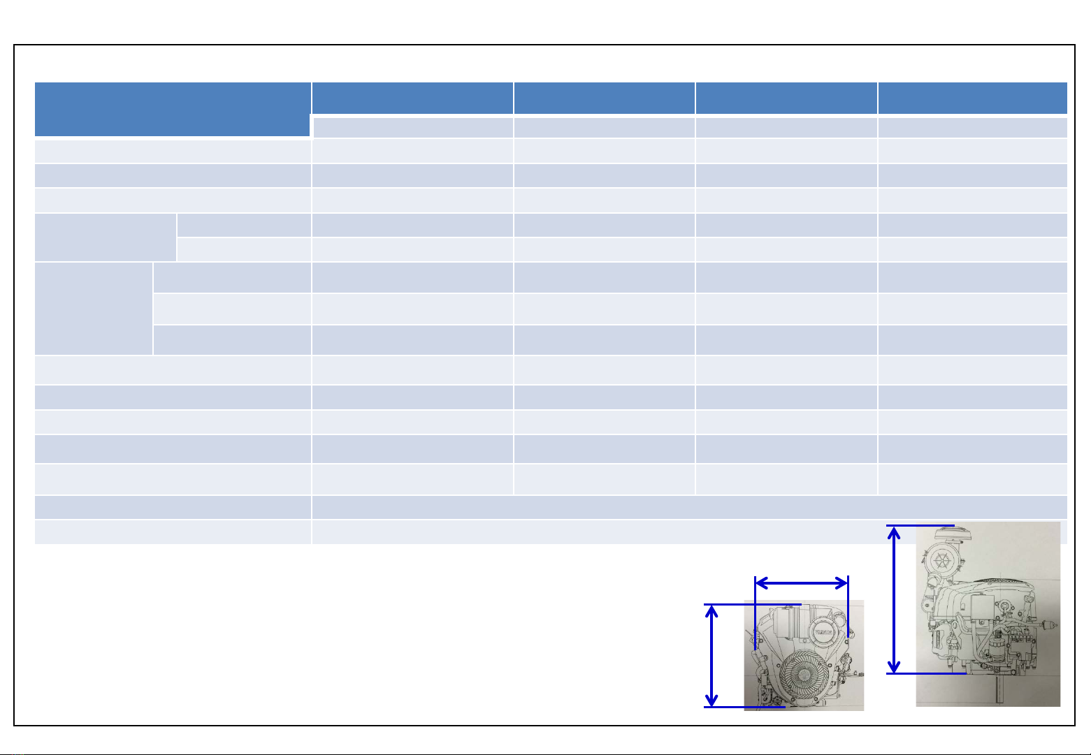
Specification
Model :MX825V-EFI
Model Name MX825V-EFI ECV 880 Vanguard 810 FX850V
Yamaha Kohler B&S Kawasaki
Dimensions* (in.) L x W x H 19.6 x 18.3 x 25.2 19.7 x 20.5 x 24 19.9 x 18.5 x 22.9 18.9 x 18.1 x 24.2
Weight –kg (lbs)60.0 (132.2) 61.7 (136) 41.3 (91) 47.6 (105)
Displacement –cc (ci) 824 (50.3) 824 (50.3) 810 (49.4) 852 (51.9)
Maximum Power
SAE J1995 (hp)
SAE J2723 33 - - 27
SAE J1940 -33 28 -
Measured
Maximum
Power
SAE J1995 (
hp)
SAE Certified Power 33.8 - - **
Measured by 3rd party -32.25 - -
Measured in house - - 28 -
Maximum Torque (ftlbs)50.1 51.1 -44.6
Bore –mm (in) 80 (3.15) 86 (3.39) 83.8 (3.30) 84.5 (3.33)
Stroke –mm (in) 82 (3.23) 71 (2.79) 73.4 (2.89) 76 (2.99)
Compression Ratio 9.1:1 8.9:1 8.4:1 8.2:1
Oil capacity (including filter)Not final na 2.1 qt.2.4 qt.
ENG configuration air cooled –vertical crankshaft
Lubrication full pressure with filter
4
499
464
639
*Competitor information from published public
data. Locations of measurements unclear.

Theme
Target
ContentPart
Performance for customer Service Tip
Model :MX825V-EFI
5
•Adopt 30 degree phase shift crank pins with internal oil passages
•Reduces vibration, and the number of parts required
•Balancer weight not needed to reduce vibration
Crankshaft
1) 30 degree phase shift design 2) Internal oil passageways
1) Reduce vibration 2) Increase reliability, reduce wear
30 degree Phase shift
#2 Crank Pin
#1 Crank Pin
Engine oil pumped from Crankcase
through the Crankshaft
Back to Oil Pan
To Con-rod Big end
•Compact engine design fits a wide variety of applications while allowing easy
access to maintenance components
•Good reliability and reduced engine wear

Theme
Target
ContentPart
Performance for customer Service Tip
Model :MX825V-EFI
6
•Thin 1st and 2nd piston rings reduce engine friction
•Short-skirt design piston also reduces friction
Piston/Piston Rings
Lightweight, short-skirt design piston, w/ thin Piston Rings
Less power is lost to friction, which means more power is available for work and
increased fuel economy.
Reduce internal engine friction
•The 1st ring can be installed either direction –the ‘R’
mark can be up or down
•The ‘RN’ mark on the 2nd ring, indicates upper side
‘R’ on 1st ring
‘RN’ on 2nd ring
The ‘RN’ mark shows upper side for 2nd ring
Thin piston rings
Short skirt
Theme
Target
ContentPart
Performance for customer Service Tip
Model :MX825V-EFI
7
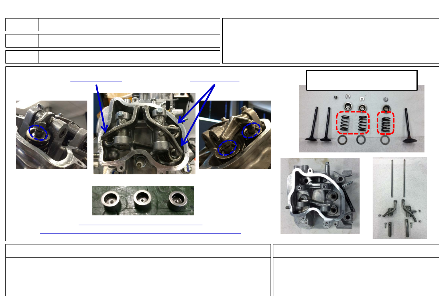
•2 inlet Valves.
•Adopt shim valve adjustment design.
Valve system
1) Multi valve (2 IN, 1EX) , 2) Shim valve adjustment design.
•High performance
•Long maintenance interval
1) High performance, 2) Long maintenance interval.
•Valve clearance:IN 0.04~0.08mm
EX 0.08~0.12mm
•Periodical Check: 1,000 hr
•Shim increments: 0.05mm
2 Intake Valves
1Exhaust Valve Valve springs for intake are
different from that for exhaust
Shims for Valve clearance adjustment
(valve adjustment procedure outlined in the Service Tips section -Click

Theme
Target
ContentPart
Performance for customer Service Tip
Model :MX825V-EFI
8
•Fan case consists of 2pieces -Fan case and Fan case cover
•There are 2maintenance hatch under fan case cover
Fan Case Cover
Fan Case Cover consists of 2parts
•Good maintainability
Easy to remove grass clippings from cooling system
•Periodical Maintenance –minimum 200 hr
•Clean cooling fan area as needed using compressed air
•Clean oil cooler and any grass that may be trapped
on backside
Fan Cover Fan Case
Maintenance hatch to
remove grass clippings

Theme
Target
ContentPart
Performance for customer Service Tip
Model :MX825V-EFI
9
•Debris screen is installed to reduce the amount of grass clippings from
entering the flywheel/cooling fan area
Debris Screen
Adopt Debris Screen
•Good maintainability
To reduce grass clippings from clogging and easy maintenance
Debris screen
•Used compressed air to remove grass clippings and
other debris when cooling system is clogged.
•Periodical Maintenance
Clean cooling area: as needed –minimum 200 hr
Theme
Target
ContentPart
Performance for customer Service Tip
Model :MX825V-EFI
10
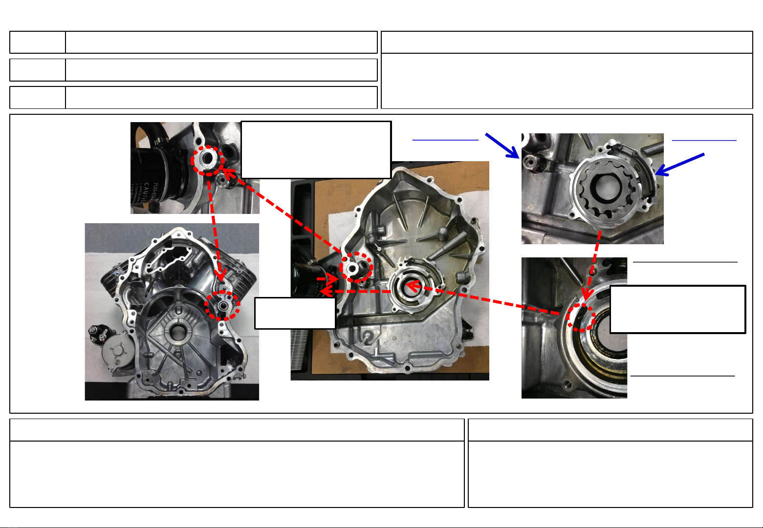
•Forced lubrication system with trochoid pump
•Trochoid pump with oil strainer and pressure relief valve
•Oil Cooler incorporated (air-cooled, radiator type)
Lubrication
Forced lubrication system
Good reliability and reduced engine wear.
Superior engine lubrication, reliability and reduced wear
Pressurized oil goes to
oil filter and oil cooler
through this hole.
To Oil filter &
Oil cooler
Oil is supplied to the
Crankshaft & Camshaft
after passing thru the oil
cooler.
Trochoid Oil Pump
Trochoid Oil Pump
Oil Strainer
Relief Valve
•Periodical maintenance
Change engine oil:100hr
Change oil filter :200hr
Table of contents
Other Yamaha Engine manuals

Yamaha
Yamaha F100C User manual

Yamaha
Yamaha EH63 User manual

Yamaha
Yamaha F200 User manual

Yamaha
Yamaha MZ250 User manual

Yamaha
Yamaha YF200 R1 User manual

Yamaha
Yamaha WB760 WaveBlaster 760 User manual

Yamaha
Yamaha F50D Building instructions

Yamaha
Yamaha XF375 User manual

Yamaha
Yamaha EH64 User manual

Yamaha
Yamaha YFM400FWA 2000 5GH3-AE1 User manual

Yamaha
Yamaha PHASER MF User manual

Yamaha
Yamaha 396 Service manual

Yamaha
Yamaha MX800V User manual

Yamaha
Yamaha 40XMH User manual

Yamaha
Yamaha TRANSERVO SSC04 User manual

Yamaha
Yamaha F150B User manual

Yamaha
Yamaha MZ175 User manual

Yamaha
Yamaha F25A User manual

Yamaha
Yamaha MZ400 Manual

Yamaha
Yamaha MZ125 User manual


