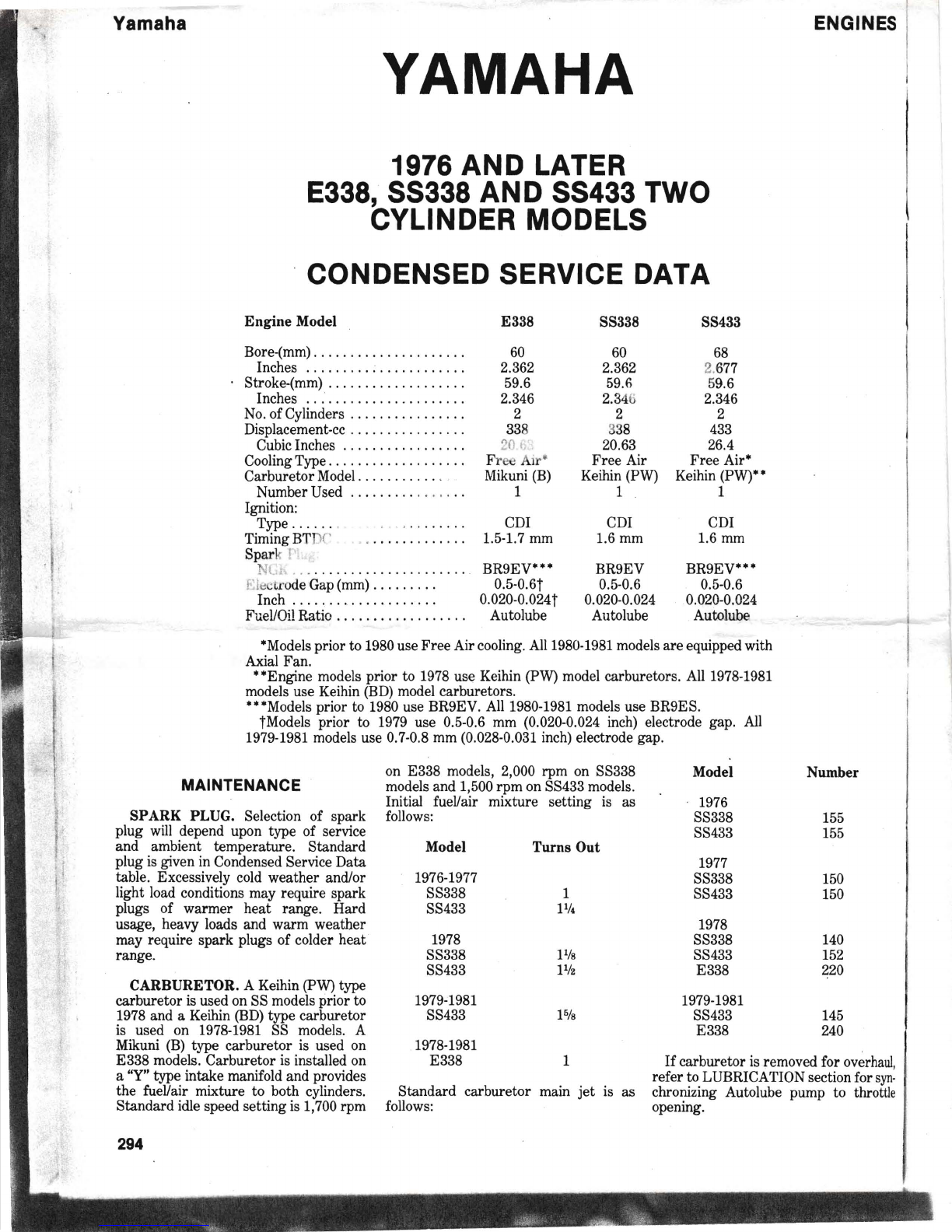
CarburetorService
ENGINE~
Fig .
14-Exploded
view
of
operat
ing
diaphragm
(7),
spr ing (8),
spr
ing
seat
(9)
and
regulator
cover
(10).
Upper
end
of
adjusting
stud
is
shown
at (A).
5---,
.......
;--11
16
17
Fig.
12-Exploded
v
iew
of
KEIHIN
d
iaphragm
type
carburetor
showing
component
parts.
S
ight
tube
(21) is
used
to
set
fuel
level
and
. is
not
a
part
of the
carburetor
.
I.
Throttle body
2. Low speed screw 12. Bleed plug
3. High speed needle 13. Spring
4. Low speed needle 14. Pivot shalt
5. Pump diap hragm 15. Valve lever
6. Pump upper cover 16. Regulating diaphrag m
7. Gasket 17. Spring
B. Pump check valves lB. Regulator cover
9. Pump (regulating) body 19. Lock screw
10. Inlet fitti ng 20. Adjust ing screw
11. Inlet needle & seat 21. Sight tube
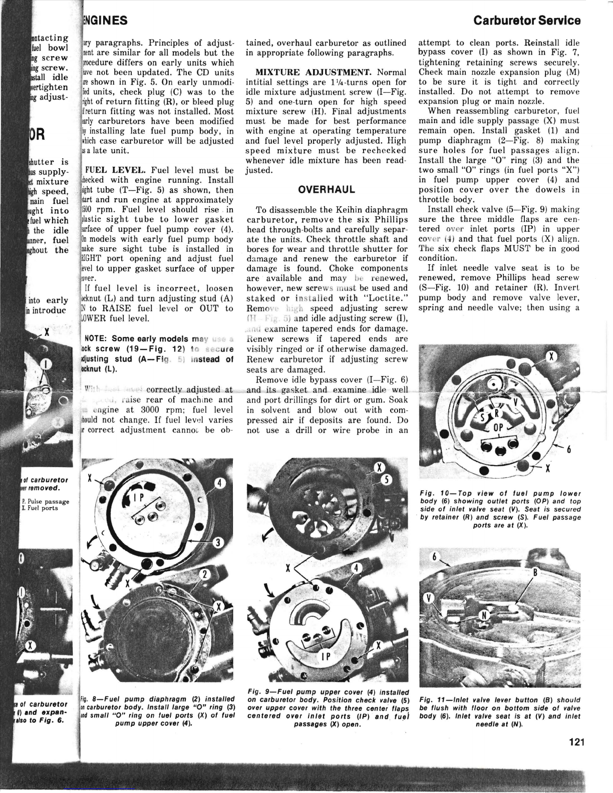
Fig.13-0perating
diaphragm
(7)
and
associ-
ated
parts
installed
on
lower
side
of
valve
body.
7. Operating diaphr agm
B. Spring P. Pulse fitti ng
9. Spring seat R. R
eturn
fitting
F. Inlet fuel fitting X. Fuel passages
good pin punch of appropriate size,
drive valve seat
(V
) 1I ,V
••
>I out of
valve body. Valve h,ts are available
in standard size and OD oversizes of
0.01 , .d 0.002 mm. Oversize valves
a
"il
t'iied by one or two annular
<J"'
S around outside of body while
standard body is smoot h. Rein
stall
retainer (R
-Fig.
10), needle valve and
lever, then check height of actuating
button
(B-Fi
g. 11) which should be
flush with valve body floor. Adjust if
neces
sary
by b
ending
t
ang
whicl
contacts valve needle (N).
Fig. 13 shows operating diaphragn
(7), spring (8) and spring seat (9
correctly positioned.
Part
s are showr
exploded in proper order in Fig. 14. Ar
initial starting point for adjusting stue
(A) in regulator cover
(1
0) is with
tW
I
threads showing when viewed fron
inside as shown. Adjust the
assem
bled
carburetor after installation as previ
ously outlined.
KEIHIN
TYPE FLOAT CARBURETOR
WITH BUTTERFLY THROTTLE
Carburetors are identified by a model
number which consists of a let
ter
prefix
"BD" followed by a
set
of numb
ers
such
as "44-38". First
par
t of number in-
dicates
thr
ottle bore (in millimeters) and
second p
art
of number indicates venturi
diameter.
ADJUSTMENT
FLOAT
LEVEL.
Float is adjusted by
bending metal
tang
between float body
(16-
Fig. 14A) and float pin (17). As
shown in Fig. 14B, distance (D) should
be 0.48-0.67 inch when carburetor is
tilted
~t
a 20-30 degree angle.
IDLE
SPEED.
Idle speed is adjusted
by turning screw
(8-Fig
. 14A). Idle
speeds vary from model to model, con-
sult respective manufacturer specifica-
tion for recommended speed setting.
IDLE MIXTURE. Idle mix
tur
e ae
justment is done by turning sere.
(6- Fig. 14A).
Start
engine and bring u
to normal operating temperature. Tur
screw either in (lean) or out (rich) to ot
tain an even engine idle. Readjust idl
speed to recommended setting
after
idl
mixture is
set
.
MAIN
JET.
To insure top p
erf
orn
ance of engine, main jet
(13-Fig
. 14
..1
may need to be changed if there is :
2000 feet change in altitude or an
1:
degree F change in temperature. Whe:
altitude or weather temperature if
creases a lower number of
jet
should b
used. Whenever altitude or weathe
temperature decreases a larger numbe
of
jet
should be used. Caution should
b.
taken especially when operating at .
lower altitude, too lean of fuel mixtur.
could shorten engine life.
.
• ..
~
~'I~
' "
......'
h. :
,l
......
,,{.
"'~.
• ..
tj;..~..
.."
\
~
.
122