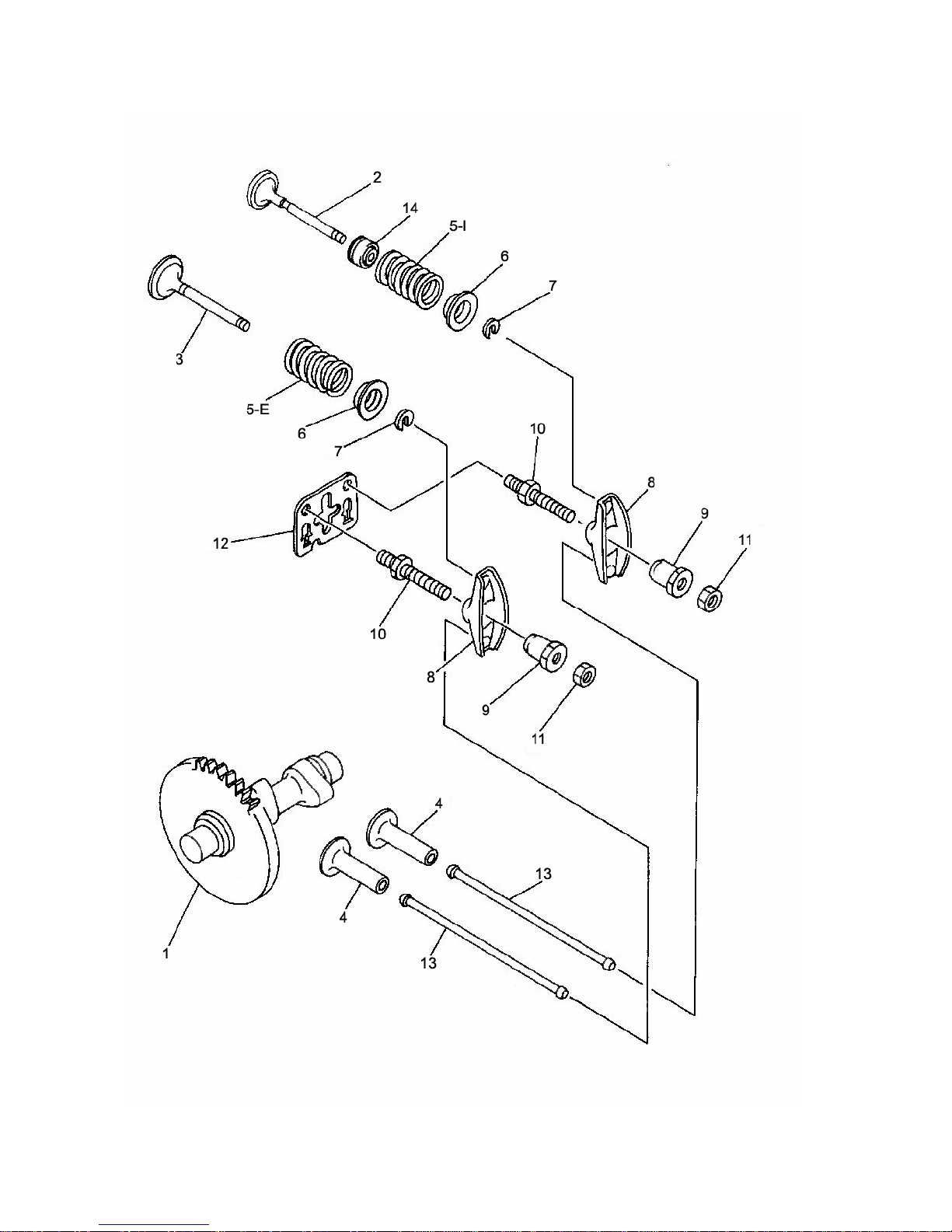
Yamaha YF200 R1 User manual


Title
Page
Block & Side Cover
4-5
Crank, Piston & Rod
6- 7
Cylinder Head
8-9
Cam & Valve train
10-11
Carburetor / Manifold
12-13
Flywheel & Ignition
14-15
Assembly & 6 Packs
16
Torque Values
17
Special Tools
18-19
Pre-Assembly
20-21
Cylinder Head Prep & Assembly
22
Final Assembly
23-25
Table of Contents
For more information about the F200 Concept and Rules
or to find Resources for your YF200 R1 please visit:
www.Speedway-Karting.com
1-1-2007
Go to www.burrisracing.com and click on Tech Shop
for the latest Updates, FAQ’s or download the most
recent version of the YF200R1 Manual.
Items in Blue are upgrades or XR (Extended Range) products

YAMAHA YF200 R1

BLOCK & SIDE COVER
YAMAHA YF200 R1
Ref # Burris P/N Description Qty
1 F21-101-00 Block / Crankcase with Sleeve 1
2 F21-102-00 Main Bearing 2
3 F21-103-00 Seal -Flywheel Side 1
4 F21-104-00 Oil Drain Plug - 10X16mm 1
5 F21-105-00 Oil Drain Plug Gasket 1
6 F21-106-00 Side Cover Dowel Pin -8mm (Solid) 2
7 F21-107-10 Side Cover Complete 1
Includes 2,7,8,10,11,12,13, & 17
8 F21-108-00 Seal - PTO (Side Cover) Side 1
9 F21-317-10 Side Cover Gasket 1
10 F21-110-00 Front Oil Filler Plug/Dip Stick 1
11 F21-111-00 Front Oil Filler Plug Gasket 1
12 F21-112-00 Rear Oil Filler Plug 1
13 F21-113-00 Rear Oil Filler Plug O-Ring 1
14 F21-114-20 Side Cover Stud - 8X44mm A-1 6
15 F21-115-10 Side Cover Flange Nut - 8mm 10.9 6
16 F21-116-00 Cylinder Sleeve 1
17 F21-117-00 Rubber Side Cover Plug 1


CRANK, PISTON & ROD
Page 7
YAMAHA YF200 R1
Ref # Burris P/N Description Qty
1 F21-200-00 Crankshaft 1
2 F21-201-01 Billet Rod Assy - Billet w/insert 1
F21-201-02 Bearing Insert For Billet Rod 1
F21-201-03 Rod Bolt & Washer Set 2
3 F21-202-00 Piston Assy. Std. (71.00mm) 1
F21-202-05 Piston Assy. +.002" (71.05mm) 1
F21-202-10 Piston Assy. +.004" (71.10mm) 1
F21-202-15 Piston Assy. +.006" (71.15mm) 1
F21-202-20 Piston Assy. +.008" (71.20mm) 1
F21-202-25 Piston Assy. +.010" (71.25mm) 1
4 F21-203-00 Ring Set Std. thru +.004" (71.00mm-71.10mm) 1
F21-203-25 Ring Set +.006" thru +.010" (71.15mm-71.25mm) 1
5 F21-204-00 Piston Wrist Pin 1
6 F21-205-00 Circlip (set of 2) 1
7 F21-206-01 Crank Shim - .008 (0.2mm) 1
F21-206-02 Crank Shim - .012 (0.3mm) 1


CYLINDER HEAD
Page 9
YAMAHA YF200 R1
Ref # Burris P/N Description Qt
y
0 F21-300-18 R1 Complete Gasket Kit w/.018" HG 1
F21-300-27 R1 Complete Gasket Kit w/.027" HG 1
F21-300-30 R1 Complete Gasket Kit w/.030" HG 1
F21-300-36 R1 Complete Gasket Kit w/.036" HG 1
F21-300-40 R1 Complete Gasket Kit w/.040" HG 1
1 F21-301-00 Cylinder Head - Bare 1
2F21-302-10 Exhaust Header Stud - 6X27mm 2
3 F21-303-00 Intake Manifold Stud - 6X18mm 2
4 F21-304-18 Head Gasket - .018" Thick 1
F21-304-27 Head Gasket - .027" Thick 1
F21-304-30 Head Gasket - .030" Thick 1
F21-304-36 Head Gasket - .036" Thick 1
F21-304-40 Head Gasket - .040" Thick 1
5 F21-305-00 Cylinder Head Stud - 8X55mm 2
6 F21-306-00 Cylinder Head Stud - 8X40mm 2
7 F21-307-00 Cylinder Head Dowel Pin -10mm 2
8 F21-308-00 Spark Plug NGK BPR6ES 1
9 F21-309-00 Exhaust Gasket 1
10 F21-310-10 Intake Gasket 1
11 F21-311-10 Exhaust Flange Nut - 6mm Grade 10.9 2
F21-311-20 Itntake Manifold Hex Nut 6mm 2
12 F21-312-00 Cylinder Head Flange Nut - 8mm 4
13 F21-313-00 Valve Cover Baffle Gasket 1
14 F21-314-00 Valve Cover Gasket 1
15 F21-315-00 Valve Cover Baffle Assy. 1
16 F21-316-00 Valve Cover 1
19 F21-319-00 Valve Cover Stud & Nut Kit 1
(4) 6X15mmStud, (4) 6mmFlange Nut, (4) Spacers


CAM & VALVE TRAIN
Page 11
YAMAHA YF200 R1
Ref # Burris P/N Description Qty
1 F21-401-00 Camshaft - Unground Lobes 1
F21-401-51 Camshaft - #51 Grind 1
2 F21-402-00 Intake Valve - 26mm 1
F21-402-20 XR Intake Valve - 26mm Stainless 1
3 F21-403-00 Exhaust Valve - 24mm 1
F21-403-20 XR Exhaust Valve - 24mm Stainless 1
4 F21-404-00 Valve Lifter 2
5-E F21-405-00 Valve Spring - Red (OEM Exhaust) 1
5-I F21-405-01 Valve Spring - Blue (OEM Intake) 1
5-E F21-405-10 XR Valve Spring - Orange (Exhaust) 1
5-I F21-405-11 XR Valve Spring - White (Intake) 1
6 F21-406-00 Valve Spring Retainer (OEM) 2
F21-406-20 XR Aluminum Valve Spring Retainer 2
7 F21-407-00 Valve Spring Ratainer Lock 2
F21-407-20 XR Valve Spring Ratainer Lock Set 2
8 F21-408-00 Rocker Arm 2
9 F21-409-00 Rocker Arm Pivot 2
10 F21-410-00 Rocker Arm Stud 2
11 F21-411-00 Rocker Arm Lock Nut 2
12 F21-412-00 Push Rod Guide Plate 1
13 F21-413-00 Push Rod (OEM) 2
F21-413-10 XR Tubular Push Rod (For OEM Valve Length) 2
F21-413-20 XR Tubular Push Rod (Extended Length For XR Valves) 2
14 F21-414-00 Intake Valve Stem Seal 1
15 F21-415-10 XR Intake & Exhaust Valve Kit 1
Valves,Locks,Retainers,Shims, Springs & Push Rods
16 F21-416-30 XR .030 Valve Spring Shim 2
17 F21-417-00 XR Stainless Valve Wear Caps 2

YAMAHA YF200 R1
Page 12

CARBURETOR / MANIFOLD
Page 13
Model Pop Off Low
speed High
Speed
Carburetor .790 Venturi 9/11 psi 2 1
Recommended Carburetor Settings (Starting Point)
Notes:
(1) When adjusting the linkage make sure the throttle shutter (butterfly) fully
closes. Also, do not set the shutter adjusting screw to idle the engine as this
will cause it to run rich when decelerating or on warm up/parade laps and
make proper LS adjustments difficult. Start the engine about 1 minute before
going onto the track and gently “crack” the throttle to keep the engine running.
(2) Adjust throttle linkage so it stops at the pedal, not the carburetor throttle
shaft
YAMAHA YF200 R1
Ref # Burris P/N Description Qty
1 F21-501-30 YF200 R1Carburetor .790 Venturi 1
2 F21-502-20 Filter Cup & Mounting Screws .790 Carb 1
3 F21-503-00 Intake Manifold Complete 1
4 F21-504-00 Air Filter 1
5 F21-505-00 Pre- Filter Wrap 1
6 F21-506-10 Yamaha YF200 R1 Thtottle Linkage Kit 1
7 F21-507-14 14mm - (.551) Jr. I Restrictor Plate 1
F21-507-16 16mm - (.630) Jr. II Restrictor Plate 1
F21-507-18 18mm - (.709) Jr. III Restrictor Plate 1
8 F21-318-10 Carburetor Flange Gasket 1
DF-44 Mikuni Fuel Pump 1
F21-508-00 YF200 R1 Fuel Pump Mounting Kit 1


FLYWHEEL & IGNITION
Page 15
YAMAHA YF200 R1
Ref # Burris P/N Description Qty
1 F21-601-00 Fan Housing 1
2 F21-602-00 Fan Housing Flange Bolt - 6X12mm 4
3 F21-603-00 T.C.I. Mounting Flange Bolt - 6X20mm 2
4 F21-604-00 Spark Plug Cap 1
5 F21-605-00 T.C.I. Unit 1
6 F21-606-00 Flywheel (offse key) 6° Advance 1
F21-606-10 Flywheel (straight key) Billet Flywheel 1
7 F21-607-00 Flywheel - OEM 1
F21-607-10 Flywheel - Billet Adjsutable Timing Hub 1
8 F21-608-00 Flywheel Nut (Starter) 3/4" Hex 1
9 F21-609-00 Flywheel Screen 1
NOTES:

Ref # Burris P/N Description Qt
y
1 F21-701-00 Exhaust Stud & Flange Nut (kit) 1
(2) 6X15mmStud, (2) 6mmFlange Nut
2 F21-702-00 Intake Stud & Flange Nut (kit) 1
(2) 6X27mm, (2) 6mmFlange Nut
3 F21-703-00 Cylinder Head Stud & Flange Nut (kit) 1
(2) 8X40mmStud, (2) 8X55mmStud, (4) 8mmFlange Nut
4 F21-704-00 Valve Cover Stud (kit) 1
(4) 6X15mmStud, (4) 6mmFlange Nut,(4) Spacers
5 F21-705-00 Side Cover Stud & Flange Nut (kit) 1
(6) 8X44mmStud, (6) 8mmFlange Nut
6 F21-706-00 FanHouseing Flange Bolt (kit) 1
(4) 6X12mmFlange Bolt
7 F21-707-00 T.C.I. Mounting Flange Bolt (kit) 1
(2) 6X20mmFlange Bolt
Ref # Burris P/N Description Qt
y
8 F21-708-00 Cylinder Head & Side Cover Flange Nu
t
6
8mmFlange Nut (six pack)
9 F21-709-00 Intake & Exhaust Flange Nut 6
6mmFlange nut (six pack)
10 F21-710-00 Cylinder Head Stud 6
8X40mmStud (six pack)
11 F21-711-00 Cylinder Head Stud 6
8X55mmStud (six pack)
12 F21-712-10 Side Cover Stud 6
8X44mmStud (six pack)
13 F21-713-00 Intake Stud 6
6X18mmStud (six pack)
14 F21-714-10 Exhaust Stud 6
6x27mmStud (six pack)
15 F21-715-00 Cylinder Head Dowel Pin 6
10mmDowel Pin (six pack)
16 F21-716-00 Side Cover Dowel Pin 6
8mmDowel Pin (six pack)
ASSEMBLY & 6 PACKS

TORQUE VALUES
Page 17
Item
in-lbs ft-lbs Nm m-kg
Connecting Rod Bolts*
150 12.5 17.3 1.7
Side Cover Nuts
240 20.0 27.6 2.8
Flywheel Nut
564 47.0 65.0 6.5
Cylinder Head Nuts
220 18.3 25.3 2.5
Rocker ArmStud
85 7.1 9.8 1.0
Rocker ArmLock Nut
75 6.2 8.6 0.9
Valve Cover Nuts
50 4.2 5.8 0.6
T.C.I. Flange Bolts
85 7.1 9.8 1.0
Flywheel Shroud
85 7.1 9.8 1.0
Oil Drain Plug
150 12.5 17.3 1.7
Intake Manifold Nuts
85 7.1 9.8 1.0
Exhaust Manifold Nuts
85 7.1 9.8 1.0
Spark Plug
160 13.3 18.4 1.8
YAMAHA YF200 R1
Note—Torque values listed above take into account using 30 wt oil or
equivalent lube on threads.

YAMAHA YF200 R1
Page 18
SPECIALTOOLS

Page 19
SPECIALTOOLS
Note: It is strongly recommended you purchase the Com-
plete Tool Kit (F21-800-00) when building your YF200 R1
engine. Possible component damage can occur during
assembly without the proper tools.
Ref # Burris P/N Description Qty
1 F21-800-00 Complete Tool Kit 1
Includes items 2,3,4,5,6,8 & 9
2 F21-801-00 Torque Plate 1
3 F21-802-00 Dowel Remover (8mm & 10mm) 1
4 F21-803-00 Seal Installer (Side Cover) 1
5 F21-804-00 Seal Installer (Block) 1
6 F21-805-00 Piston Installer (71.0mm & 71.05mm) 1
7 F21-805-10 Piston Installer (71.1mm & 71.20mm) 1
8 F21-806-00 6mm Stud Installer 1
Intake, Exhaust, & Valve Cover
9 F21-807-00 8mm Stud Installer 1
Side Cover & Head
YAMAHA YF200 R1

Pre-Assembly
• Thoroughly clean and inspect parts prior to assembly for damage and compatibility
•
• Crank & Rod Prep: Check the crank journals for any nicks or scratches
and remove them with a fine stone to prevent damage to the bearing seat
areas. Check the rod bolt holes to be sure the bolts seat properly and burr or
lap mating edges of connecting rod insert bearing to insure proper clearance.
•
• Cam Prep: Inspect the cam gear and lobes for burrs. If necessary, deburr
& polish these areas. Thoroughly clean the cam to remove scale or blasting
media left from the heat-
treating process.
Lapping the Block: Lap the
cylinder head and motor
mount surfaces on a surface
plate to remove any burrs or
irregularities. This will insure
proper sealing for the head
and also keep from binding
the crank when the engine is
attached to the motor mount.
•
• Fitting the Piston: Remove
all sharp edges from piston
with a deburring wheel or fine
sand paper. Hone the block
using a 280/400 grit stone to achieve .0035 - .0055” piston to cylinder
clearance (measure the piston 90° from the wrist pin and ¼” from the
bottom). Finish the bore with a plateau hone using about 15/20 strokes. After
the piston has been fitted clean the block with hot soapy water and spray the
bore and bearing with WD-40 to prevent rust.
•
• Setting the Ring Gap: Note it is very
important to follow the manufacturers
recommended ring gap settings. Running
too tight of a gap on the top and second
rings will result in cylinder damage and
cutting the expander on the oil ring will result in a loss in oil control. We have
run the top 2 rings at .010+ gap and the oil rings as supplied for a full season
with excellent results. (See piston ring instructions supplied with piston)

•
•
•
• Seal Installation: The face of the seal should be .290 below the aluminum
boss surface on the block and .200 on the side cover. When installing the seals
it is important to apply grease on the O.D. to prevent scuffing or tearing of the
seal. We have tools available (see “Special Tools”) to install these seals that
seat them at these predetermined depths.
•
• Stud Installation: Apply a small
amount of (blue) Loctite to the threads of
the dimpled end of the stud and install
using a stud driver as shown. (see
“Special Tools”) Note-there are two
different ends to the studs; dimpled and
rounded— install the dimpled end in the
block. Run the stud down until it lightly
bottoms and tighten it ¼ turn more. (An
alternative method to the stud driver is to use a nut and jam nut)
•
• Dowel Installation: When installing the dowels
be sure the holes are clean and they slide in
easily. Place a small amount of grease on the
dowels before installing them in the block, head
and side cover. When removing the dowels, use
the removal tool to eliminate the possibility of
damage. (see “Special Tools”).
•
Pre-Assembly
Page 21
YAMAHA YF200 R1
Table of contents
Other Yamaha Engine manuals

Yamaha
Yamaha YSE series User manual

Yamaha
Yamaha VF150 User manual

Yamaha
Yamaha XF375 User manual

Yamaha
Yamaha E115A User manual

Yamaha
Yamaha PHASER MF User manual

Yamaha
Yamaha MA190 User manual

Yamaha
Yamaha MZ250 User manual

Yamaha
Yamaha YDS3 User manual

Yamaha
Yamaha F4 User manual

Yamaha
Yamaha T 135 SE User manual