manuals.online logo
Brands
  1. Home
  2. •
  3. Brands
  4. •
  5. Oriental motor
  6. •
  7. Engine
  8. •
  9. Oriental motor K Series User manual

Oriental motor K Series User manual

1

 
製品の取り扱いは、電気・機械工学の専門知識を持つ有資格者が行なってください。
お使いになる前に、「安全上のご注意」をよくお読みのうえ、正しくお使いください。
また、本文中の警告・注意・重要に記載されている内容は、必ずお守りください。
この製品は、一般的な産業機器への組み込み用として設計・製造されています。
その他の用途には使用しないでください。この警告を無視した結果生じた損害の補
償については、当社は一切その責任を負いませんので、あらかじめご了承ください。

ここに示した注意事項は、製品を安全に正しくお使いいただき、お客様や他の人々
への危害や損傷を未然に防止するためのものです。内容をよく理解してからお使い
ください。
㆙࿌
この警告事項に反した取り扱いをすると、死亡または重傷を負う場
合がある内容を示しています。
ὀព
この注意事項に反した取り扱いをすると、傷害を負うまたは物的損
害が発生する場合がある内容を示しています。
重要製品を正しくお使いいただくために、お客様に必ず守っていただき
たい事項を本文中の関連する取り扱い項目に記載しています。
㆙࿌
••爆発性雰囲気、引火性ガスの雰囲気、腐食性の雰囲気、水のかかる場所、可燃物の
そばでは使用しないでください。火災・感電・けがの原因になります。
••設置、接続、運転・操作、点検・故障診断の作業は、適切な資格を有する人が行なっ
てください。火災・感電・けがの原因になります。
••通電状態で移動、設置、接続、点検の作業をしないでください。電源を切ってから
作業してください。感電の原因になります。
••設置するときは、モーターに手が触れないようにするか、接地してください。•
感電の原因になります。
••モーターは筐体内に設置してください。感電・けがの原因になります。
••電源入力電圧は、定格値を必ず守ってください。火災・感電の原因になります。
••接続は接続図にもとづき、確実に行なってください。火災・感電の原因になります。
••リード線を無理に曲げたり、引っ張ったり、はさみ込んだりしないでください。
火災・感電の原因になります。
••付属のコンデンサの接続端子は絶縁処理してください。感電の原因になります。
••停電したときは、電源を切ってください。停電復旧時にモーターが突然起動して、
けが・装置破損の原因になります。
••電源を切った直後(30 秒以内)は、コンデンサの接続端子に触れないでください。
残留電圧により、感電の原因になります。
••モーターを分解・改造しないでください。感電・けがの原因になります。
ὀព
••モーターの仕様値を超えて使用しないでください。感電・けが・装置破損の原因に
なります。
••運転中および停止後しばらくの間は、モーターに触れないでください。モーターの
表面が高温のため、やけどの原因になります。
••モーター出力軸、モーターリード線を持たないでください。けがの原因になります。
••モーターの周囲には、可燃物を置かないでください。火災・やけどの原因になります。
••モーターの周囲には、通風を妨げる障害物を置かないでください。装置破損の原
因になります。
••モーターは過熱保護装置を内蔵していません。外部に保護装置を設けてください。
••運転中は回転部(出力軸、冷却ファン)に触れないでください。けがの原因になり
ます。
••異常が発生したときは、ただちに電源を切ってください。火災・感電・けがの原因
になります。
••モーターは、正常な運転状態でも、表面温度が 70•°Cを超えること
があります。運転中のモーターに接近できるときは、図の警告ラベ
ルをはっきり見える位置に貼ってください。•
やけどの原因になります。 警告ラベル
••製品は、法令または自治体の指示に従って、正しく処分してください。

 
次のものがすべて揃っていることを確認してください。不足したり破損している場
合は、お買い求めの支店・営業所までご連絡ください。
••モーター•......................................1台
••コンデンサ•..................................1個
••取扱説明書 (本書 )•.....................1部
 
製品が正しいか、製品に表示された品名で確認してください。
モーターの品名、電圧、出力、コンデンサ容量は、銘板記載事項を見て確認してく
ださい。
品名 モーター品名 コンデンサ品名
5TK40GU-AF-50HZ 5TK40GU-AF CH400CFAUL2
5TK40GU-AF-60HZ CH300CFAUL2
5TK40A-AF-50HZ 5TK40A-AF CH400CFAUL2
5TK40A-AF-60HZ CH300CFAUL2

 
モーターは機器組み込み用に設計、製造されています。
風通しがよく、点検が容易な次のような場所に設置してください。
••屋内に設置された筐体内(換気口を設けてください)
••使用周囲温度••‒10 ~ +50•℃(凍結しないこと)
••使用周囲湿度••85%以下(結露しないこと)
••爆発性雰囲気、有害なガス(硫化ガスなど)、および液体のないところ
••直射日光が当たらないところ
••塵埃や鉄粉などの少ないところ
••水(雨や水滴)、油(油滴)、およびその他の液体がかからないところ
••塩分の少ないところ
••連続的な振動や過度の衝撃が加わらないところ
••電磁ノイズ(溶接機、動力機器など)が少ないところ
••放射性物質や磁場がなく、真空でないところ
••標高 1000•m以下
 
モーター後部の空気吸込口をふさがないように、ファンカバーの後ろを 10•mm以上
あけるか、換気穴をあけてください。

z

モーターとギヤヘッドのインロー部を平行にして、
ギヤヘッドをゆっくり左右に回しながらモーター
に組み付けます。このとき、モーター出力軸の歯
切り部分がギヤヘッドの側板やギヤに強く当たら
ないようにしてください。
モーター出力軸を上向きにした状態で、組み付け
てください。
モーター
出力軸の
歯切り部
分
イン
ロー部
側板

取付板に穴をあけ、別売りのギヤヘッド付
属のねじ4本を使用し、モーターとギヤヘッ
ドを取付板に固定してください。
取付板との間にすき間がないように設置し
てください。
ねじの寸法は当社 WEBサイトをご覧くだ
さい。
モーター
ギヤヘッド
ねじ(ギヤヘッドに付属)
取付板
ナット
平座金
重要••モーターの歯切りタイプと同じ歯切りタイプのギヤヘッドを組み付けて
ください。
••モーターとギヤヘッドを無理に組み付けたり、ギヤヘッド内部に金属片
などの異物が入らないようにしてください。モーター出力軸の歯切りや
ギヤに傷が付いて、異常音や寿命低下などの原因になります。
HM-9433
 お買い上げいただきありがとうございます。
この取扱説明書には、製品の取り扱いかたや安全上の注意事項を示しています。
••取扱説明書をよくお読みになり、製品を安全にお使いください。
••お読みになったあとは、いつでも見られるところに必ず保管してください。
K
リード線タイプ
••この取扱説明書の一部または全部を無断で転載、複製することは、禁止されてい
ます。
••取扱説明書に記載されている情報、回路、機器、および装置の利用に関して産業
財産権上の問題が生じても、当社は一切の責任を負いません。
••製品の性能、仕様および外観は改良のため予告なく変更することがありますので
ご了承ください。
••取扱説明書には正確な情報を記載するよう努めていますが、万一ご不審な点や誤り、
記載もれなどにお気づきの点がありましたら、最寄りのお客様ご相談センターまで
ご連絡ください。
•••は、日本その他の国におけるオリエンタルモーター株式会社の登
録商標または商標です。
©•Copyright•ORIENTAL•MOTOR•CO.,•LTD.•2008
2019 年 9 月制作
2

z
取付板に穴をあけ、ねじを使用し、モーター
を取付板に固定してください(取付用のねじ
は付属していません)。取付板との間にすき
間がないように設置してください。
ねじの呼び:M6
締付トルク:3.0•N·m モーター
取付板
ねじ
ナット
平座金
重要取付穴にモーターを斜めに挿入したり、無理に組み付けたりしないでく
ださい。フランジインローに傷が付き、モーターが破損するおそれがあ
ります。
 
付属コンデンサの容量が、モーター銘板に記載されてい
る容量と合っているか確認してください。
M4 のねじ(付属していません)を使用して、確実に取り
付けてください。
Ø4.3mm
重要••コンデンサ取付用のねじの締付トルクは、取付足の破損防止のため•
1•N·m以下にしてください。
••コンデンサは、モーターから 10•cm以上離して取り付けてください。
モーターの熱で、コンデンサの寿命が短くなります。

モーターリード線と電源接続部、コンデンサ接続部など、すべての接続部は、絶縁
処理をしてください。
コンデンサ端子接続部の絶縁処理用には、別売のコンデンサキャップをご用意して
おります。
 
ギヤヘッドの減速比によっては、ギヤヘッド出力軸の回転方向はモーター出力軸の
回転方向と逆になります。詳しくは、当社 WEBサイトをご覧ください。
 
モーターの回転方向は、モーター出力軸側から見た場合です。時計方向を CW、反
時計方向を CCWとしています。接続図中の色はリード線の色を示しています。
電源
L
N
橙
スイッチ(SW)をCW側に接続すると時計方向、
CCW
側に接続すると反時計方向に回転します。
グレー
白
黒
橙
SW CCW
CW
R0C0
R0C0
CW
 
モーターの起動 /停止や回転方向の切り替えにスイッチを使用する場合は、接点保
護のため、サージ電圧吸収用 CR回路を接続してください。
R
0
C
0R0=5 ~ 200•Ω
C0=0.1 ~ 0.2•µF•250•VAC
オプション(別売)として用意しています。•品名:
EPCR1201-2
 
リード線径は、AWG20•(0.5•mm2)と同等またはそれ以上のリード線を使用してく
ださい。
 
モーターの取り付けフランジの裏面に 4 か所の座を設けてあります。必要に応じて
座部の塗装をはがして止め、ボルトと一緒にアース線を固定してください。

電源を投入するとモーターが回転します。
感電防止のため、配線が終わるまで電源は入れないでください。
重要••モーターを運転するときはモーターケース温度を 90•°C以下に抑えてく
ださい。90•°Cを超えて運転すると、モーターの巻線、ボールベアリン
グの寿命が短くなります。モーターケースの温度は、温度計、サーモテー
プ、または熱電対で測定・確認してください。
••付属のコンデンサを使用し、モーターが起動した後もコンデンサは常
時接続しておいてください。

印加電圧により、時間定格が異なります。
単相 60•V以下の場合は連続運転が可能です。(連続定格)
単相 100•Vの場合は連続運転可能時間が 5 分となっています。(5 分定格)

モーターの運転操作が正常に行なえないときは、この項をご覧になり適切に処置して
ください。それでも正常に運転できないときは、最寄りのお客様ご相談センターにお
問い合わせください。
現•象 確認内容
モーターが回転しない。•
モーターが低速で回転する。
••電源電圧を確認してください。
••電源とモーターを正しく接続してください。
••付属のコンデンサを正しく接続してください。
••端子台や圧着端子を使用している場合、接続不良に
なっていないか確認してください。
••負荷を許容値以下にしてください。
モーターが回転したり、
しなかったりする。
••電源とモーターを正しく接続してください。
••付属のコンデンサを正しく接続してください。
••端子台や圧着端子を使用している場合、接続不良に
なっていないか確認してください。
指定した方向と逆に回転す
る。
••「接続図」を見て、正しく接続してください。
••付属のコンデンサを正しく接続してください。
••ギヤヘッドの減速比によっては、モーター出力軸と
ギヤヘッド出力軸の回転方向が逆になります。•
詳しくは、当社 WEBサイトをご覧ください。
••回転方向は、モーター出力軸側から見た場合です。
見る方向を確認してください。
モーターが異常に熱くなる。
(モーターケースの温度が•
90•°Cを超えている。)
••電源電圧を確認してください。
••付属のコンデンサを正しく接続してください。
••換気条件を見直してください。
異音がする。
••モーターとギヤヘッドを正しく組み付けてください。
••モーターと同じ歯切りタイプのギヤヘッドを組み付
けてください。
4端子コンデンサ
内部配線図
1
Introduction
 Before using the motor
Only qualied personnel should work with the product. Use the product correctly
after thoroughly reading the section “Safety precautions.” In addition, be sure to
observe the contents described in warning, caution, and note in this manual.
The product described in this manual has been designed and manufactured to be
incorporated in general industrial equipment. Do not use for any other purpose.
Oriental Motor Co., Ltd. is not responsible for any damage caused through failure to
observe this warning.
Safety precautions
The precautions described below are intended to prevent danger or injury to the
user and other personnel through safe, correct use of the product. Use the product
only after carefully reading and fully understanding these instructions.
WARNING
Handling the product without observing the instructions that
accompany a“Warning” symbol may result in serious injury or
death.
CAUTION
Handling the product without observing the instructions that
accompany a“Caution” symbol may result in injury or property
damage.
Note
The items under this heading contain important handling
instructions that the user should observe to ensure safe use of
the product.
WARNING
•Do not use the product in explosive or corrosive environments, in the presence of
ammable gases, locations subjected to splashing water, or near combustibles. Doing so
may result in re, electric shock or injury.
•Assign qualied personnel the task of installing, wiring, operating/controlling, inspecting
and troubleshooting the product. Failure to do so may result in re, electric shock or
injury.
•Do not transport, install the product, perform connections or inspections when the
power is on. Always turn the power o before carrying out these operations. Failure to
do so may result in electric shock.
•Install the motor so as to avoid contact with hands, or ground it to prevent the risk of
electric shock.
•Install the motor in an enclosure in order to prevent electric shock or injury.
•Keep the input-power voltage within the specication to avoid re and electric shock.
•Connect the cables securely according to the connection diagram in order to prevent re
and electric shock.
•Do not forcibly bend, pull or pinch the lead wires. Doing so may result in re and electric
shock.
•Be sure to insulate the connection terminal of the capacitor. Failure to do so may result in
electric shock.
•Turn o the power in the event of a power failure, or the motor will suddenly start when
the power is restored and may cause injury or damage to equipment.
•Do not touch the connection terminal of the capacitor immediately after the power is
turned o (for a period of 30 seconds). The residual voltage may cause electric shock.
•Do not disassemble or modify the motor. This may cause electric shock or injury.
CAUTION
•Do not use the motor beyond its specications, or electric shock, injury or damage to
equipment may result.
•Do not touch the motor during operation or immediately after stopping.
The surface is hot and may cause a skin burn(s).
•Do not hold the motor output shaft or motor lead wires. This may cause injury.
•Keep the area around the motor free of combustible materials in order to prevent re or
a skin burn(s).
•To prevent the risk of damage to equipment, leave nothing around the motor that would
obstruct ventilation.
•The motor does not have a built-in overheat protection device. Provide a protection
device externally.
•To prevent bodily injury, do not touch the rotating parts (output shaft, cooling fan) of the
motor during operation.
•When an abnormality is noted, turn o the power immediately, or re, electric shock or
injury may occur.
•The motor surface temperature may exceed 70 °C (158 °F) even under
normal operating conditions. If the operator is allowed to approach
the running motor, attach a warning label as shown in the gure in a
conspicuous position. Failure to do so may result in a skin burn(s). Warning label
•Dispose the product correctly in accordance with laws and regulations, or instructions of
local governments.
Preparation
 Checking the product
Verify that the items listed below are included. Report any missing or damaged items
to the branch or sales oce from which you purchased the product.
•Motor ............................................. 1 unit
•Capacitor ...................................... 1 piece
•Operating manual..................... 1 copy (this document)
 Checking the model name
Check the model number against the number indicated on the product.
Make sure the motor’s model name, voltage, output and capacitor capacitance,
which are listed on the nameplate.
Model Motor model Capacitor model
5TK40GU-AF-50HZ 5TK40GU-AF CH400CFAUL2
5TK40GU-AF-60HZ CH300CFAUL2
5TK40A-AF-50HZ 5TK40A-AF CH400CFAUL2
5TK40A-AF-60HZ CH300CFAUL2
Installation
 Location for installation
The motor is designed and manufactured for installation in equipment.
Install it in a well-ventilated location that provides easy access for inspection.
The location must also satisfy the following conditions:
•Inside an enclosure that is installed indoors (provide vent holes)
•Operating ambient temperature −10 to +50 °C (+14 to +122 °F) (non-freezing)
•Operating ambient humidity 85%, maximum (non-condensing)
•Area that is free from an explosive atmosphere or toxic gas (such as sulfuric gas) or liquid
•Area not exposed to direct sun
•Area free of excessive amount dust, iron particles or the like
•Area not subject to splashing water (storms, water droplets), oil (oil droplets) or other
liquids
•Area free of excessive salt
•Area not subject to continuous vibration or excessive shocks
•Area free of excessive electromagnetic noise (from welders, power machinery, etc.)
•Area free of radioactive materials, magnetic elds or vacuum
•1000 m (3300 ft.) or less above sea level
 How to install the motor
When installing a motor with cooling fan onto a device, leave 10 mm (0.39 in.) or
more behind the fan cover or open a ventilation hole so that the cooling inlet on the
back of the motor cover is not blocked.
zPinion shaft type
Assembling
Keep the pilot sections of the motor and gearhead
in parallel, and assemble the gearhead with
the motor while slowly rotating it clockwise/
counterclockwise. At this time, note so that the
pinion of the motor output shaft does not hit
the side panel or gears of the gearhead strongly.
Assemble the gearhead to the motor in a condition
where the motor output shaft is in an upward
direction.
Pinion of
the motor
output shaf
t
Pilot
section
Side
panel
Installing
Drill holes on the mounting plate and x the
motor and gearhead on the plate using screws
supplied with the gearhead. Do not leave a gap
between the motor and mounting plate.
Refer to the Oriental Motor Website for the
screw specications.
Motor
Screws
(supplied with the motor)
Gearhead
Mounting plate
Nuts
Washers
Note
•Use the gearhead with pinion shaft which is identical with one of motor.
•Do not forcibly assemble the motor and gearhead. Also, prevent metal
objects or foreign substances from entering in the gearhead. The pinion
of the motor output shaft or gear may be damaged, resulting in noise
or shorter service life.
HM-9433
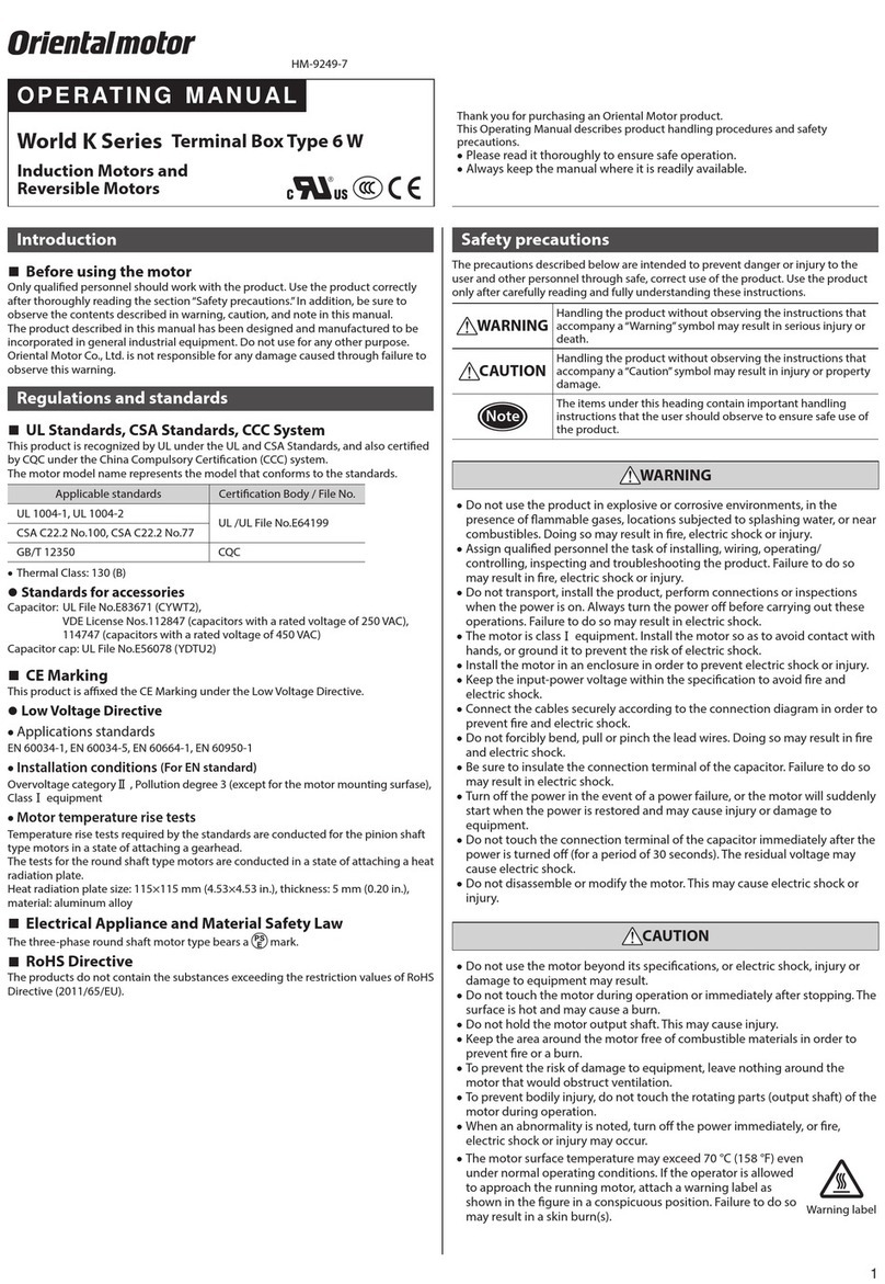
OPERATING MANUAL Thank you for purchasing an Oriental Motor product.
This Operating Manual describes product handling procedures and safety
precautions.
•Please read it thoroughly to ensure safe operation.
•Always keep the manual where it is readily available.
KSeries Torque Motors
Lead Wire Type
•Unauthorized reproduction or copying of all or part of this manual is prohibited.
•Oriental Motor shall not be liable whatsoever for any problems relating to industrial
property rights arising from use of any information, circuit, equipment or device
provided or referenced in this manual.
•Characteristics, specications and dimensions are subject to change without notice.
•While we make every eort to oer accurate information in the manual, we welcome
your input. Should you nd unclear descriptions, errors or omissions, please contact the
nearest oce.
•is a registered trademark or trademark of Oriental Motor Co., Ltd., in
Japan and other countries.
© Copyright ORIENTAL MOTOR CO., LTD. 2008
Published in September 2019
T
echnical Support Tel:(800)468-3982
8:30
A.M. to 5:00 P.M., P.S.T. (M-F)
7:30
A.M. to 5:00 P.M., C.S.T. (M-F)
www
.orientalmotor.com
Schiessstraße 44, 40549 Düsseldor
f, Germany
T
echnical Support Tel:00 800/22 55 66 22
www
.orientalmotor.de
T
el:01256-347090
www
.oriental-motor.co.uk
T
el:01 47 86 97 50
www
.orientalmotor.fr
T
el:02-93906346
www
.orientalmotor.it
T
el:+55-11-3266-6018
www
.orientalmotor.com.br
• Please contact your nearest Oriental Motor oce for further information.
4-8-1Higashiueno
,Taito-ku,Tokyo 110-8536
Japan
T
el:03-6744-0361
www
.orientalmotor.co.jp
Tel:0800-060708
www.orientalmotor.com.tw
Singapore
Tel:1800-8420280
www.orientalmotor.com.sg
Tel:1800-806161
www.orientalmotor.com.my
Korea
Tel:080-777-2042
www.inaom.co.kr
Tel:1800-888-881
www.orientalmotor.co.th
Tel:400-820-6516
www.orientalmotor.com.cn
Tel:+91-80-41125586
www.orientalmotor.co.in
Hong Kong Branch
Tel:+852-2427-9800
2
zRound shaft type
Drill holes on the mounting plate and x the
motor on the plate using screws (not supplied).
Do not leave a gap between the motor and
mounting plate.
Nominal diameter of screw: M4
Tightening torque: 3.0 N·m (26 lb-in) Motor
Mounting plate
Screws
Nuts
Washers
Note Do not insert the motor into the mounting hole at an angle or force it in,
as this may scratch the ange pilot section and damage the motor.
 Mounting the capacitor
Before mounting the provided capacitor, check that the
capacitor’s capacitance matches that stated on the motor’s
name plate. Mount the capacitor securely by using M4
screws (not provided).
Ø4.3 mm
(0.169 in.)
Note
•Do not let the screw fastening torque exceed 1 N·m (8.8 lb-in) to
prevent damage to the mounting foot.
•Mount capacitor at least 10 cm (3.94 in.) away from the motor. If it is
located closer, the life of the capacitor will be shortened.
Connection
Insulate all the wire connections, such as the connection between the motor and the
capacitor connection. Use the accessory (sold separately) capacitor cap to insulate
the capacitor terminal connection.
 Rotating direction of the gearhead output shaft
The rotating direction of the gearhead output shaft may be opposite that of the
motor shaft, depending on the gear ratio. Refer to the Oriental Motor Website for
details.
 Connection diagram
The direction of motor rotation is as viewed from the side of the motor’s output
shaft. The motor rotates in a clockwise (CW) and counterclockwise (CCW) direction.
Colors shown in the connection diagram indicate the colors of lead wires.
Po
wer
supply
L
N
Orange
T
he motor rotates in the clockwise direction if the
switch(SW
) is connected to the CW side, and it
rotates in the counterclock
wise direction if
connec
ted to the CCW side.
Gray
White
Black
Orange
SW CCW
CW
R0C0
R0C0
CW
zFor protection of contact (switch)
If the switch is used for starting/stopping the motor or switching the rotation direction,
connect the CR circuit for surge suppression in order to protect the contacts.
R
0
C
0R0=5 to 200 Ω
C0=0.1 to 0.2 µF 250 VAC
It is provided as an accessory (sold separately). Model: EPCR1201-2
 Lead Wire for Power Supply
For power supply, use a thicker lead wire than the motor lead wire.
AWG20 (0.5 mm2)
 Connecting Protective Earth Terminal
For motors without a Protective Earth Terminal, any one of the four mounting bolts
may be used to attach the ground wire to the motor case. If necessary, remove all
paint that may impede conductivity around the bolt mounting hole.
Operation
The motor rotates when the power supply is turned on.
For protection against electric shock, do not turn on the power supply until the
wiring is complete.
Note
•Make sure that the motor case temperature does not exceed 90 °C (194°F)
when operating the motor. Operation exceeding case temperature 90°C
(194 °F) may signicantly deteriorate the coils and ball bearings of the
motor and shorten the motor's life span. Motor case temperature can be
measured by xing a thermometer on the motor surface. It can also be
measured using thermo tape or a thermocouple.
•The motors use a capacitor and keep it connected even after rotation of
the motor has started.
Time rating
The time rating will vary, depending on the impressed voltage.
The motors can be operated continuously when powered with 60VAC or less.
(continuous)
The motors can operate continuously for up to 5 minutes when powered with
100VAC. (5minute rating)
Troubleshooting
When the motor cannot be operated correctly, refer to the contents provided in this
section and take appropriate action. If the problem persists, contact your nearest
oce.
Phenomena Check items
Motor does not rotate or
rotates slowly.
•Check the power supply voltage.
•Connect the power supply and the motor orrectly.
•With a single-phase motor, connect the supplied
capacitor correctly.
•If terminal blocks or crimp terminals are used, check
them for poor connection.
•Keep the load at or below the allowable value.
Motor sometimes rotates
and stops.
•Connect the power supply and the motor correctly.
•With a single-phase motor, connect the supplied
capacitor correctly.
•If terminal blocks or crimp terminals are used, check
them for poor connection.
The motor rotates in the
direction opposite to the
specied direction.
•Connect correctly by referring to“Connection diagram.”
•With a single-phase motor, connect the supplied
capacitor correctly.
•The rotating direction of the motor output shaft may
be dierent from that of the gearhead output shaft
depending on the gear ratio of the gearhead. Refer to
the Oriental Motor Website for details.
•The rotating direction is indicated as viewed from the
motor output shaft. Check the reference direction.
Motor temperature
abnormally high [Motor
case temperature
exceeds 90 °C (194 °F)]
•Check the power supply voltage.
•With a single-phase motor, connect the supplied
capacitor correctly.
•Review the ventilation condition.
Noisy operation
•Assemble the motor and gearhead correctly.
•Assemble a gearhead of the same pinion type as the
motor.
Capacitor internal
wiring diagram

This manual suits for next models

4

Other Oriental motor Engine manuals

Oriental motor BLF Series User manual

Oriental motor

Oriental motor BLF Series User manual

Oriental motor PK Series User manual

Oriental motor

Oriental motor PK Series User manual

Oriental motor World K Series User manual

Oriental motor

Oriental motor World K Series User manual

Oriental motor PKP56 Series User manual

Oriental motor

Oriental motor PKP56 Series User manual

Oriental motor NX Series User manual

Oriental motor

Oriental motor NX Series User manual

Oriental motor K II Series User manual

Oriental motor

Oriental motor K II Series User manual

Oriental motor PKP Series User manual

Oriental motor

Oriental motor PKP Series User manual

Oriental motor PK Series User manual

Oriental motor

Oriental motor PK Series User manual

Oriental motor FH Series User manual

Oriental motor

Oriental motor FH Series User manual

Oriental motor 2TK3GN-AW2J User manual

Oriental motor

Oriental motor 2TK3GN-AW2J User manual

Oriental motor AR Series User manual

Oriental motor

Oriental motor AR Series User manual

Oriental motor Alpha Step AZ Series User manual

Oriental motor

Oriental motor Alpha Step AZ Series User manual

Oriental motor 2IK6GN-AWTJ User manual

Oriental motor

Oriental motor 2IK6GN-AWTJ User manual

Oriental motor Super Vexta UPD564-NAA User manual

Oriental motor

Oriental motor Super Vexta UPD564-NAA User manual

Oriental motor K II Series User manual

Oriental motor

Oriental motor K II Series User manual

Oriental motor PKP Series User manual

Oriental motor

Oriental motor PKP Series User manual

Oriental motor BLE Series User manual

Oriental motor

Oriental motor BLE Series User manual

Oriental motor K ⅡS Series User manual

Oriental motor

Oriental motor K ⅡS Series User manual

Oriental motor World K Series User manual

Oriental motor

Oriental motor World K Series User manual

Oriental motor DGII Series User manual

Oriental motor

Oriental motor DGII Series User manual

Oriental motor K Ⅱ Series User manual

Oriental motor

Oriental motor K Ⅱ Series User manual

Oriental motor BLE2 Series User manual

Oriental motor

Oriental motor BLE2 Series User manual

Oriental motor BH Series User manual

Oriental motor

Oriental motor BH Series User manual

Oriental motor World K Series User manual

Oriental motor

Oriental motor World K Series User manual

Popular Engine manuals by other brands

Idex Gast 4AM Series Operation and maintenance manual

Idex

Idex Gast 4AM Series Operation and maintenance manual

Lenze MDERA 056 V1 Series Wiring diagram

Lenze

Lenze MDERA 056 V1 Series Wiring diagram

Fiamma 98655Z111 Installation and usage instructions

Fiamma

Fiamma 98655Z111 Installation and usage instructions

Briggs & Stratton 210000 Series Operator's manual

Briggs & Stratton

Briggs & Stratton 210000 Series Operator's manual

Binks AX160L Service manual

Binks

Binks AX160L Service manual

Assun AM-CL2642GAE Series product manual

Assun

Assun AM-CL2642GAE Series product manual

Xinchai 490B Series manual

Xinchai

Xinchai 490B Series manual

Tecumseh LEV 80-120 Operator's manual

Tecumseh

Tecumseh LEV 80-120 Operator's manual

Andersen RA2052001300 product manual

Andersen

Andersen RA2052001300 product manual

Atlanta TS Operating and maintenance instructions

Atlanta

Atlanta TS Operating and maintenance instructions

Stiga TRE 352 Operator's manual

Stiga

Stiga TRE 352 Operator's manual

Parker EY Series Technical manual

Parker

Parker EY Series Technical manual

GEA TPS operating instructions

GEA

GEA TPS operating instructions

MVVS 116 - V1.1 ASSEMBLY EXHAUSTS... manual

MVVS

MVVS 116 - V1.1 ASSEMBLY EXHAUSTS... manual

BAFANG FM G320.250.R user manual

BAFANG

BAFANG FM G320.250.R user manual

Briggs & Stratton Vanguard 110000 Operator's manual

Briggs & Stratton

Briggs & Stratton Vanguard 110000 Operator's manual

Panthera Motosports PM07-18 installation guide

Panthera Motosports

Panthera Motosports PM07-18 installation guide

Deutz 0297 9929en Operation manual

Deutz

Deutz 0297 9929en Operation manual

manuals.online logo
manuals.online logoBrands
  • About & Mission
  • Contact us
  • Privacy Policy
  • Terms and Conditions

Copyright 2025 Manuals.Online. All Rights Reserved.